
Related Manuals for Honeywell IP Receiver


Summary of Contents for Honeywell IP Receiver
-
Page 1: User Guide
Honeywell 网络接警机(IP Receiver) 说明书 User Guide © 2009 Honeywell International Inc. All rights reserved. http://www.cn.security.honeywell.com/ P/N: 800-01188 Rev. A... -
Page 3: Table Of Contents
Honeywell 目录 产品介绍........................... 1 产品示意图 ........................3 前面板 ......................... 3 后面板 ......................... 4 系统配置........................... 5 功能操作........................... 6 网络操作........................... 9 网络操作初始化......................9 登录........................... 10 配置........................... 11 查询........................... 12 导出记录 ........................13 修改密码 ........................13 退出系统 ........................14 接警平台网络结构及路由器配置..................15... - Page 4 System Configuration..................... 23 Operations........................24 Network Operations ....................... 27 Initialization ....................... 27 Login ......................... 28 Configuration ......................29 Search ........................30 Export Result Records....................31 Changing Password ....................31 Logout........................32 Network Structure of IP Receiver and Configuration on Router ........33...
-
Page 5: 产品介绍
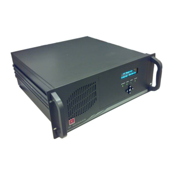
Honeywell 1 产品介绍 网络接警机通过以太网接收 IP 模块发出的报警信息并将其转发到接警中心。网络接警机 可以连接多家公司的多种型号的网络报警设备,基于 TCP 协议提供可靠通信,通过 RS232 串 口线将接收到的警情上报到 CMS 接警中心,并保存在自身数据库中。用户可以通过前面板按 键、显示屏查询报警信息,以及登录“网络接警机系统”查询、管理、备份收到的警情。 网络接警机具有以下功能: • 最多连接 10000 个报警设备(由软件狗决定) • 自身最多能存储 10,000,000 条报警消息 • 提供“网络接警机系统”供用户远程登录进行数据库和配置操作 • 显示屏和操作按键,可用于查询 • 系统操作状态 LED 显示 • 通过 RS232 串口线连接 CMS 接警中心 • 每天凌晨 00:00,如果数据库中保存的数据大于 1,000,000 条,则会删除最老的... - Page 6 Honeywell 产品规格: 180~265V AC 输入电压 177mm(H)×482.6mm(W)×452mm(D) 尺寸 重量 15.20 kg 4 行、20 字符真空荧光显示(VFD) 显示屏 安装方式 机架式安装 工作温度 0℃~50℃ 装箱清单: 名称 数量 1 台 网络接警机 1 本 说明书 1 条 串口线...
-
Page 7: 产品示意图
Honeywell 2 产品示意图 前面板 网络接警机前面板示意图: 图 2-1 网络接警机前面板示意图 编号 名称 编号 名称 VFD 显示屏 系统状态灯 排风口 报告状态灯 ENTER/MENU(确认/菜单键) 网络指示灯 通讯指示灯 四向导航键 LED 指示灯状态说明见下表: 指示灯 说明 当有 IP 设备连接到网络接警机时,绿灯亮;无任何设备连 ETHERNET 接时,绿灯灭。 当网络接警机与 CMS 接警中心串口连接时,绿灯亮;未连 COMM 接时,红灯亮。 EVENT 上报警情时,绿灯闪烁。 当系统处于非正常工作状态,前面板与主板的串口线未连 SYSTEM 接,红灯亮;正常运行时,绿灯亮。... -
Page 8: 后面板
Honeywell 后面板 后面板接口示意图如下所示: 图 2-2 网络接警机后面板示意图 编号 名称 编号 名称 三芯交流电源接口 千兆网口 1 (220V 输入) COM2 千兆网口 2 COM4 COM3 硬盘状态灯 USB2.0 系统电源灯 PS/2 接口 主机开关 CMS 接警中心可以通过交叉串口线连接至网络接警机上的 COM2 端口。通信端口 COM2 为 9 针 COM 端口。... -
Page 9: 系统配置
Honeywell 3 系统配置 图 2-2)分别配置了默认的IP地址,分别为 网络接警机在出厂时为两个千兆网口(见 192.168.0.2 和 192.168.1.2。用户可根据需要为这两个网口配置另外的IP地址,具体步骤如 下: 配置需要与接警机相连的 PC 机网卡,修改其对应网络连接的 Internet Protocol(TCP/IP) 属性,属性窗口如下图所示: 图 3-1 Internet Protocol(TCP/IP) 属性窗口 在上图所示的窗口中,选择“使用下面的 IP 地址”,并在“IP 地址”中设置一个与 默认 IP 地址处于同一子网的 IP 地址(例如 192.168.0.3 或 192.168.1.3)。点击 【确定】按钮完成配置。 将 PC 机与网络接警机的千兆网口相连。 如第一步中配置的 IP 地址为 192.168.0.X,则 PC 机应与千兆网口 1 相... -
Page 10: 功能操作
Honeywell 4 功能操作 根据下表操作说明,进行接警机前面板屏幕操作: 屏幕提示 操作说明 通电后,打开主机开关,前面板的 4 个 LED 灯轮流点亮,屏 幕显示“Starting…”。 图 直到系统正常启动,前面板显示名称和时间。 图 在系统正常工作状态中,按►或 ENTER 键进入菜单。 按▲和▼键翻看选项;按►或 ENTER 键选择菜单项;按◄键 图 2)。 返回待机界面(见 图 查询报警事件 图 中选择“Search Alarm”,显示左图菜单。 在 共有三种查看方式:全部警情(All Alarms)、已上报警情 (Reported Alarm)、未上报警情(Unreported Alarm)。 未上报警情(Unreported Alarm):如果网络接警机未能和 CMS 接警中心连接,那么收到的警情全部储存在数据库中, 图... - Page 11 Honeywell 按时间查询 图 中选择“Search by Time”,显示左图菜单。 在 默认显示当前时间,可以按►和◄键来选择需要调整的时间选 项,按▲和▼调整数字。 图 在 YEAR(年)选项按◄键返回上级菜单(见 图 6)。 在 SECOND(秒)选项按►键可按照设定时间来查找数据库 图 7),并返回设定时间之前的最近一条;如果没有警 (见 情,则返回设定时间之后发生的最近一条警情。 图 显示警情 查找出来的警情包括: • Account — 帐号(4 位帐号或者 6 位帐号的后 4 位) • CID(Contact ID)、G(Group ID)、防区号(C)/用 户号(U)(根据上报警情而定) • IP — 上报警情的设备 IP 地址(如无法获取到 IP 信息,...
- Page 12 Honeywell • 无任何按键操作 30 秒后,屏幕自动返回待机画面(见 图 2)。 注意 • 每天凌晨 0:0:0 时,系统会对前面板屏幕进行检测,屏幕状态依次 全亮 2 秒、全灭 2 秒、回到正常待机状态。...
-
Page 13: 网络操作
Honeywell 5 网络操作 网络操作初始化 由于网络接警机需要与路由器相连,必须为网络接警机分配一个未被其他设备占用的固 定IP地址。用户可最多可为接警机分配 2 个IP地址。在进行系统配置以后(见第5页 系统配置 一节),根据如下步骤配置网络接警机的IP地址: 在IE中输入http://192.168.0.2或http://192.168.1.2进入网络接警机系统登录页面(登 图 录页面见 5-2)。 登录 登录网络接警机系统。详细内容参见第10页 一节。 在“配置”页面下,在“网络地址 1”中为千兆网口 1 设置一个未被其他设备占用 的 IP 地址,在“网络地址 2”中为千兆网口 2 设置未被其他设备占用的 IP 地址。点 击【执行】保存配置内容。 配置 下图为网络接警机的配置页面(参见第11页 一节获取更多信息): 图 5-1 网络接警机 IP 初始配置 网络地址 1 对应于千兆网口 1 的 IP 地址,网络地址 2 对应于千兆网口... - Page 14 Honeywell 登录 当网络接警机与PC机属于同一子网时,在PC机Internet Explorer(IE)中输入接警机的 IP地址(需查看具体IP地址,请参见第6页第4章节中的 图 10)登录网络接警机系统。 如果PC机属于外网、网络接警机属于路由器内网时,需先按第6章节 注意 (第15页)对路由器进行配置,再在IE中输入路由器WAN端的IP地址 登录网络接警机系统。 图 5-2 网络接警机系统登录 图 输入用户名和密码(默认用户名和密码:admin/admin),点击【登录】进入系统( 5-4)或点击【重置】清空用户名和密码。 如果用户名或密码错误,则显示以下提示信息: 图 5-3 用户名密码错误...
- Page 15 Honeywell 图 5-2)。 点击“返回重新登录”,返回到登录页面( 配置 成功登录系统后,显示如下页面。系统包括三个功能标签页:“配置”、“查询”和 “报告”。在页面右上角可以选择“修改密码”和“退出”,其下方显示当前的版本号。 图 5-4 配置 “网络配置”页面显示两个网卡的相应的网址、子网掩码和网关地址。可直接在输入框 中修改参数,修改完成后点击【执行】,保存新配置,显示下图提示: 图 5-5 配置成功...
- Page 16 Honeywell 如果网址不完整或出现大于“255”的情况,系统将显示错误提示信 注意 息。 查询 点击“查询”标签页,进入查询页面: 图 5-6 查询 页面左侧列出六种查询方式:按帐号查询、按时间查询、按网址查询、按 CID 查询、组 合查询和高级查询。其中,“高级查询”支持输入 sql 查询语句;“组合查询”把各个组合的 查询综合到一起显示在查询结果中。 在页面左侧点击任一查询方式显示各查询页面,输入相应信息,点击【执行】,以报告 的形式显示查询结果。...
-
Page 17: 导出记录
Honeywell 图 5-7 查询结果 每页显示 20 条数据,通过点击页数编号或者“下一页”、“最后一页”可以查看相应页 面。 导出记录 图 5-7所示)的左下角点击【导出】按钮,可以将查询结果记录中的 在查询结果页面(如 最近 5000 条记录导出到Excel文件中。如查询结果记录总数小于 5000 条,则按时间由近至远 的顺序导出所有记录,如查询结果记录总数大于 5000 条,则导出最近 5000 条记录。 修改密码 在页面右上角点击“修改密码”,显示如下页面:... -
Page 18: 退出系统
Honeywell 图 5-8 修改密码 输入当前密码,并输入新密码并再次确认,点击【确认】,完成修改密码操作。提示修 改密码成功: 图 5-9 修改密码成功 注意 当前密码输入错误或者两次新密码输入不一致时,将显示错误提示。 退出系统 在页面右上角点击“退出”,则退出系统并返回到登录页面。... -
Page 19: 接警平台网络结构及路由器配置
Honeywell 6 接警平台网络结构及路由器配置 连接在广域网的报警设备的报警信息通过路由器转发给处于局域网的网络接警机,因此 需要对路由器进行一定配置以保证网络接警机安全、有效接警(以下配置以 Tenda TEI6624 路 由器为例)。 在IE中输入http://192.168.0.1,打开路由器配置界面。 关闭 DHCP 功能:DHCP 自动分配 IP 地址,可能造成网络接警机 IP 地址不固定, 从而无法接警。 DHCP 配置页面如下图所示: 图 6-1 DHCP 配置 设置虚拟服务器以便接受广域网报警,需要设置的端口有:TCP-7838、TCP- 4001、TCP-4002,启用这些端口以便网络接警机能有效的收到广域网的报警。 虚拟服务器配置页面如下图所示:... - Page 20 Honeywell 图 6-2 虚拟服务器配置 安全设置:安全设置对网络接警非常重要。 • 忽略来自 WAN 口的 Ping 包,避免恶意侦测。 • 启用防网络攻击,防止 DOS 攻击。 • 启用过滤功能,仅允许通过 TCP-7838、TCP-4001、TCP-4002 端口的数据 包,防止恶意入侵。 • 加强路由器密码管理,避免密码被破解。 忽略来自 WAN 口的 Ping 包: 图 6-3 WAN 口 Ping...
- Page 21 Honeywell 启用防网络攻击: 图 6-4 防网络攻击 过滤端口配置: 图 6-5 客户端过滤 最后,将路由器密码设置为安全性较高的密码(位数不少于 15,由字母+数字+特殊 符号组成)。 经过以上配置后,网络安全性将大大增加,有助于网络安全接警。...
- Page 22 Honeywell 中国 RoHS 根据信息产业部等部委颁布的《电子信息产品污染控制管理办法》及相关标准的要求, 网络接警机的相关信息如下: 产品的环保使用期限为 10 年,保证该环保使用期限的安装及使用注意事项见 产品使用手册; 产品中有毒有害物质或元素的名称及含量见下表: 产品中有毒有害物质或元素的名称及含量 有毒有害物质或元素 部件名称 铅 汞 镉 六价铬 多溴联苯 多溴二苯醚 (Pb) (Hg) (Cd) (Cr(VI)) (PBB) (PBDE) 箱体组件 印刷电路板组件 线缆 电源模块 LED 显示器 O:表示该有毒有害物质在该部件所有均质材料中的含量均在 SJ/T11363-2006 标准规 定的限量要求以下。 X:表示该有毒有害物质至少在该部件的某一均质材料中的含量超出 SJ/T11363-2006 标准规定的限量要求。...
-
Page 23: Introduction
CMS with a RS232 serial port cable, and stores alarms in its database. You can search the alarms with the keys and display on the front panel, and log in the IP Receiver System to search, manage and back up the received alarms. - Page 24 Honeywell Specifications: 180~265V AC Voltage Input 177mm(H)×482.6mm(W)×452mm(D) Dimension Weight 15.20 kg Display 4 lines, 20 characters VFD Mounting Rack Mounting 0℃~50℃ Operating Temperature Package checklist: Name Quantity IP Receiver User Guide Serial port cable...
-
Page 25: Interfaces And Wiring
IP Receiver. The indicator turns green when IP Receiver is connected to COMM the serial port of CMS and turns red when IP Receiver is not connected to CMS. The indicator is green and flashes when IP Receiver is EVENT reporting alarms. -
Page 26: Rear Panel
Gigabit Ethernet port 2 COM4 COM3 HDD Indicator USB2.0 Power Indicator PS/2 Power ON/OFF switch CMS can be connected to the COM2 port on IP Receiver with a crossover serial port cable. The communication port COM2 is a 9-pin COM port. -
Page 27: System Configuration
Ethernet port 1; if the IP address set in step 1 is 192.168.1.X, connect your PC to gigabit Ethernet port 2. Log in “IP Receiver System” to change the network configuration (if IP Receiver is connected to gigabit Ethernet port 1, enter http://192.168.0.2... -
Page 28: Operations
There are three options for searching alarms: “All Alarms”, “Reported Alarm” and “Unreported Alarm”. Unreported Alarm: If IP Receiver is not connected with CMS, all the alarms are stored in the database of IP Receiver as unreported alarms. - Page 29 Figure 9 alarms (Reported), number of unreported alarms (Unreported) and two IP addresses (IP1 and IP2) of the two network ports on IP Receiver for connecting IP devices. Press ▲ and ▼ to turn the page up and down; Figure 10 Press ►, ◄...
- Page 30 Honeywell The screen displays “Scanning” after a while the front panel and motherboard are not linked by a serial port cable (in 1 minute). Figure 11 Shut down Turn off the switch on the rear panel (No.12 in Figure 2-2). It costs about 15 seconds to end the programs before displaying “Shutting down…”.
-
Page 31: Network Operations
5 Network Operations Initialization If IP Receiver is to be connected to a router, you must assign a static IP address that is not occupied by other device for IP Receiver, and you can assign at most 2 IP addresses. After... -
Page 32: Login
Honeywell Login When IP Receiver and your PC belong to the same subnet, input the IP address of IP Receiver in Internet Explorer (IE) on your PC to login into IP Receiver. If the PC is connected to the internet and IP Receiver is connected to... -
Page 33: Configuration
Honeywell Configuration After you log in the system, you can see the following page. The system includes three functional tabs, which are Configuration, Search, and Reports. On the top-right corner of the page, you can select “Change password” or “Log out”, below which is the current version. -
Page 34: Search
Honeywell Search Click the Search tab to enter the Search page Figure 5-6 Search In the left pane there lists 6 search ways: by account, by time, by IP address, by CID, combination search, and advanced search. Among them “Advanced search” supports the SQL query sentences and “Combination search”... -
Page 35: Export Result Records
Honeywell Each page can display at most 20 records. To browse through the pages click Next or Last. Export Result Records Click Export on the “Report” result page (see Figure 5-7) and you can export the latest 5000 records that you searched to the Excel file. If the result records are less than 5000, all the records you have searched are exported to the XLS file in which the records are arranged in reverse chronological order. -
Page 36: Logout
Honeywell Error information is displayed if the current password entered is Note incorrect or the new password and confirm password do not match. Logout Click “Log out” on the top-right corner of the page can log out the system and return to the... -
Page 37: Network Structure Of Ip Receiver And Configuration On Router
6 Network Structure of IP Receiver and Configuration on Router Alarms from WAN devices are transmitted to the IP Receiver that is connected to the LAN by router, so it’s a must to configure router to assure the safe and effective alarm report of IP Receiver (refer to the following configuration steps that are performed on a BELKIN router). - Page 38 Honeywell Figure 6-2 Virtual Servers Setting Security setting: Security setting is very important for receiving alarms via network. • Block the Ping packets from the WAN port to avoid malicious detection. • Enable the function of anti network attack to prevent DOS attack.
- Page 39 Honeywell Ignore the Ping packets from WAN port: Figure 6-3 WAN Ping Blocking The configuration for filters: Figure 6-4 Client IP Filters Lastly set a strong password for the router (minimum of 15 characters in length, composed of letters, numbers, and special characters).
- Page 40 35F Tower A, City Center, 100 Zun Yi Road, Shanghai 200051, China TEL +86 21 52574568 FAX +86 21 62370740 Honeywell Security (China) Co., Ltd. Building 9 Tower B, Huaide Industrial Zone, Fuyong Town, Baoan District, Shenzhen, China TEL +86 0755 27326500 FAX +86 0755 27391736 ©...