Table of Contents
Quick Links
Instruction Manual
INK JET PRINTER FOR INDUSTRIAL MARKING
HITACHI Printer
Thank you for purchasing the Hitachi IJ Printer Model PH.
This printer employs a noncontact, ink-jet method to print onto a print target.
This instruction manual describes the basic operating procedures, maintenance procedures, and other detailed
handling procedures of the Hitachi IJ Printer Model PH.
If the printer is improperly handled or maintained, it may not operate smoothly and may become defective or
cause an accident. It is therefore essential that you read this manual to gain a complete understanding of the
printer and use it correctly.
After thoroughly reading the manual, properly store it for future reference.
IF you changed the language of the screen by mistake, see Chapter 5.5 "Selecting Languages".
Model PH
Table of Contents

Related Manuals for Hitachi PH


Summary of Contents for Hitachi PH
- Page 1 HITACHI Printer Model PH Thank you for purchasing the Hitachi IJ Printer Model PH. This printer employs a noncontact, ink-jet method to print onto a print target. This instruction manual describes the basic operating procedures, maintenance procedures, and other detailed handling procedures of the Hitachi IJ Printer Model PH.
- Page 2 SAFETY PRECAUTIONS ● Before using the printer, thoroughly read the following safety precautions for optimum printer use. ● You should observe the precautions set forth below in order to use the product properly and avoid endangering you or other persons or damaging property. For the purpose of clarifying the severity of injury or damage and likelihood of occurrence, the precautions are classified into two categories, WARNING and CAUTION, which both describe a hazardous situations that may arise if you ignore the precautions and perform an incorrect handling or operating...
- Page 3 SAFETY PRECAUTIONS (Continued) WARNING ● Ensure that there is no flame- or arc-generating device around the printer. The ink and makeup are both flammable and may cause fire. Fire can be generated by matches, lighters, cigarettes, heaters, stoves, gas burners, welders, grinders and static electricity. Arcs may be generated from open-type relays, switches, and brush motors.
- Page 4 Read and understand the appropriate Material Safety Data Sheet (MSDS) before using any ink or makeup. ● Use Hitachi approved consumables and periodic replacement parts. Using products that are not designated by Hitachi could cause s failure in certain functions. ● Warning for Mercury -- THE LAMP IN THIS PRODUCT CONTAINS MERCURY.
- Page 5 SAFETY PRECAUTIONS (Continued) WARNING ● When charging a refill of ink or makeup, exchanging ink, or otherwise handling ink or makeup, take enough care not to spill ink or makeup. If you spill any ink or makeup by mistake, wipe it off neatly and promptly with wiping paper or something similar.
- Page 6 (Continued) CAUTION ● Only persons who have completed an operator training course for Hitachi IJP can operate and service the printer. If the printer is operated or serviced incorrectly, it may malfunction or break down. ● Do not attempt to make repairs for any purpose other than operation or maintenance.
-
Page 7: Fcc Notice
SAFETY PRECAUTIONS (Continued) FCC Notice This device complies with part 15 of the FCC Rules. Operation is subject to the following two conditions: (1) This device may not cause harmful interference, and (2) this device must accept any interference received, including interference that may cause undesired operation. This equipment has been tested and found to comply with the limits for a Class A digital device, pursuant to part 15 of the FCC Rules. -
Page 8: Table Of Contents
CONTENTS 1. Overview ........1-1 1.1 Item Delivered. - Page 9 3.3.5 Printing the characters indicating the number of elapsed days ....3-19 3.3.6 Printing month with 3 alphabet characters ....... 3-20 3.3.7 Printing week number .
- Page 10 6.3 Standard Communication Functions......6-5 6.3.1 Printings Transmission ..........6-5 6.3.2 Print Data Recall / Transmission .
- Page 11 7.7 Adjusting the Ink Stream Position......7-17 7.8 Cleaning the Gutter ........7-19 7.9 Ink Filter Replacement .
-
Page 12: Overview
1. Overview 1.1 Items Delivered ●Unpack the order you received, and check that the following items are supplied. Item name Quantity Parts No. Remarks 1 IJ printer body Instruction man- 3 One-page sheet Used for ink particle shape confirmation, ink beam 4 Magnifying glass 451274 position confirmation, and... - Page 13 Item name Quantity Parts No. Remarks For external communication 13 Cable seal cable sealing. Cable clamp Nozzle rubber seal 14 Cable clamp One-page sheet Vinyl bag with fastener Used for storage of One-page sheet and nozzle rubber seal. Used for ink replacement 16 Drainage tube 451676 and filter replacement.
-
Page 14: Usage Precautions
1.2 Usage Precautions 1.2.1 Notes on ink and makeup ink (1) Ink and makeup ink replenishment The printer employs an automatic ink/makeup ink replenishment system. While the printer is operated, the ink reservoir automatically supplies the ink and the makeup ink reservoir automatically supplies the makeup ink to the ink main tank at regular intervals. - Page 15 (3) Storage precautions Store the ink and makeup ink in a cold dark place (0 to 20 ). (Observe this rule ℃ no matter whether tanks are unsealed or not.) The storage validity period is predefined for the ink and makeup ink. Begin to use the ink/makeup ink before the "Expiration date"...
-
Page 16: Handling Precautions
Handling precautions a. When you use the JP-K60, JP-F63, JP-K68, JP-K70, JP-T71, JP-K77,JP-E78, JP-K81, JP-K84 or JP-B85 ink, you must complete the print head air-purge procedure without regard to the humidity predominating in the employed environment. (See Section 1.2.6, "Print head air purge".) b. -
Page 17: Maintenance
f. JP-T71 and JP-T75 will change color if retorting processing (heating with hot water or steam) is done after printing. Since water is necessary for change of color, the change will not occur if heating is done with hot air. Be sure to perform ex ante evaluation for color changeability. - Page 18 If the sediment cannot be removed, replace the main ink tank. When replacing the main ink tank, contact your Hitachi distributor. (2) Caution when continuously running for 24 hours a day for more than a month When continuously running the printer for 24 hours without stopping it even once a day for more than a month, perform "ink circulation"...
-
Page 19: Ij Printer Long-Term Shutdown
1.2.2 IJ printer long-term shutdown In the case where the operation of the IJ printer is irregular (the IJ printer is shut down for a few weeks in a row, for instance) in conjunction with production and so on, there is a possibility of occurrence of a problem such as no ink ejecting when operating the printer or no recovery possible due to accretion of the ink inside the printer. -
Page 20: Print Head Cleaning
1.2.3 Print head cleaning Cleaning with the makeup ink should be limited to the end of the print head. To clean the end of the print head with the makeup ink, orient the end of the print head downward. Do not pour the makeup ink over this section. - Page 21 When using JP-K60, JP-K69 and JP-K84 ink, the following precautions must be observed. Since charging and deflecting electrodes and a gutter are provided inside the print head, if highly conductive carbon black settles on the print head mounting base (made of insulating material), leakage can occur between these electrodes resulting in frequent recurrence of errors.
-
Page 22: Shutdown (No-Cleaning Stop)
1.2.4 Shutdown (no-cleaning stop) When you press the Shut down key on the upper right-hand corner of a screen, the printer stops after completing its automatic nozzle cleaning sequence. If you repeatedly activate the Shut down key to stop an operation, excessive makeup ink enters the printer, thereby thinning the ink or producing an unduly high ink main tank solution level. -
Page 23: Cautions On Operating Time When Printer Is In Service
1.2.5 Cautions on operating time when printer is in service Caution when daily operating time is relatively short: If you frequently perform the shutdown procedure,excessive makeup ink enters the printer,therby thinning the ink. For the stable using,you must keep terms of the graphs. [The ink contais MEK and aceton] [The ink contains Ethanol] (JP-K26, G27, K27, R27, K28, K33, K61,... -
Page 24: Print Head Air Purge
1.2.6 Print head air purge If the makeup ink remains in the electrode section after cleaning or if you use the IJ printer at a high humidity, moisture condensation may occur within the print head, causing leakage from the deflection electrode section. -
Page 25: Heating Of Ink
1.2.7 Heating of ink (1) If ambient temperature is under approximately 20 , the ink is heated by heating unit ℃ which established in print head. If the heating carried out, the time of startup process is prolonged. Non-heating : approximately 1.5 minutes Heating : maximum approximately 10 minutes. -
Page 26: Gutter Cleaning
1.2.9 Gutter cleaning The IJ printer collects ink not used for printing, from the gutter. At the same time, it sucks in atmospheric gas, dust and other matter from the air. If these substances are mixed with ink in the gutter, undissolved components by the ink or makeup ink may stick to the gutter. -
Page 27: Component Names And Functions
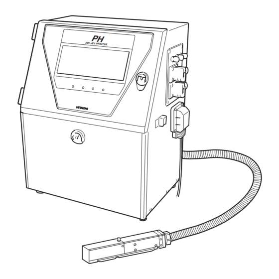
1.3 Component Names and Functions 1.3.1 External views Handle Operating status indicator lamps Turn it by 90 degrees to open and close it. Displays "Ready", "Fault" and "Warning" Various signals intakes See "1.5 Connection of signals." Power switch Push ON-push OFF altanative. Power lamp Maintenance cover Opened/closed for ink... -
Page 28: Main Body Internal Parts Arrangement
1.3.2 Main body internal parts arrangement Main ink tank Makeup ink reservoir Ink reservoir Ink filter Maintenance cover Operation panel cover Various signals connecting portion ●Component Names and Functions 1-17... -
Page 29: Print Head
1.3.3 Print head Print head cover lock thumbscrew Nozzle Charge electrode Plus deflection electrode Minus deflection electrode Gutter 1-18 ● Component Names and Functions... -
Page 30: Installing Precautions
1.4 Installing Precautions WARNING ● Ensure that there is no flame- or arc-generating device around the printer. The ink and makeup are both flammable and may cause fire. Fire can be generated by matches, lighters, cigarettes, heaters, stoves, gas burners, welders, grinders and static electricity. - Page 31 (8) If ambient humdity is 85 to 90%RH, you must purge inside of print head by air. It is necessary for dry-clean air, refulator for pressure of air and air filter. (Quantities of the air are 1L / minutes.) (9) When installing the print head and print head cable, comply with the following con- ditions.
- Page 32 (14) If you try to fix the print head with a magnetic substance (such as iron), the cover switch will malfunction resulting in an "Cover Open" error. This, you must only use nonmagnetic resins or metals for fixing the print head. (15) In the case of carrying the printer proper, put in your hands from the direction of the arrow in the drawing below.
-
Page 33: Connection Of Signals
1.5 Connection of signals 1.5.1 Wiring Precautions (1)If noise enters the IJ printer from the outside, there is the danger of erroneous operation or trouble. To improve noise resistance, perform wiring work as follows: Separate the power cable to the IJ printer from other power lines for powering use (especially, power line for a speed control inverter, etc.). - Page 34 (3) Precautions related to welding current of welder Signal (weak electric) ground and frame ground are connected because the ink drops of the IJ printer are electrically charged. Column The ink drops are electrically charged by Charge electrode of ink Nozzle impressing a voltage between the charging electrode and ink column as shown at the...
-
Page 35: Overview
1.5.2 Overview As for wiring of the input-output lines, open the operation panel cover and draw the lines from the ports on the side, and connect them to the external connection terminal blocks 1, 2 and the external communication connector inside. Caution When performing wiring work, always turn off the power. - Page 36 ● Layout of connectors for connection External connection External connection terminal block 1 terminal block 2 (TB1) (TB2) Communication connector ●Connection to the external connection terminal block (TB1) Input/ Name Remarks number output Print target detector power supply Output 12 VDC; maximum: 80 mA Print target detector Input Print target detector ground...
- Page 37 ● Connection to the external connection terminal block (TB2) Pin number Name Remarks (NOTE) Ready NC :Normally closed NO :Normally open COM:Common Fault Warning ● Terminal specification : M4 ● Connection to the external communication (RS-232C) connector Pin number Name Input/Output Remarks (NC)
- Page 38 Notices on connecting the cable Cable seal block Fixing screw Claw Cable seal block Seal Seal Tightening nut Cable Cable Remove the fixing screw and take Remove the tightening nut. the cable seal block off the printer Put the cable through as in the proper.
-
Page 39: Connection Of Various Signal
1.5.3 Connection of various signal When handling an external signal, be sure to comply with the voltage, current and time described herein. We cannot guarantee the operation unless it is handled correctly. 1.5.3-1 Ready output signal The following describes the wiring of the signal that is outputted to the outside for the purpose of indicating that the IJ printer is ready state. - Page 40 Diode system (applicable to DC, inapplicable to AC) Diode The peak inverse voltage of the employed diode must be at least 10 times as high as the employed voltage, and its forward current must be larger than the load current. 1.5.3-2 Fault signal output The following describes the wiring of the signal that is outputted to the outside for the purpose of indicating that the IJ printer is in the fault mode.
- Page 41 1.5.3-3 Warning signal output The following describes the wiring of the signal that is outputted to the outside for the purpose of indicating that the IJ printer is in the warning mode. (a) When using the NO contact (make contact) Status indicator 8-9 contact lamp or the like...
- Page 42 1.5.3-4 Print target detector (a) When a dedicated power supply is not used If the print target detector current consumption is not more than 80 mA, no dedicated power supply is required because adequate power can be supplied from the IJ printer built-in power supply. In such a situation, make wiring connections and perform setup as indicated below.
- Page 43 (b) When a dedicated power supply is used If the print target detector current consumption is more than 80 mA, furnish a dedicated power supply. In this instance, make wiring connections and perform setup as indicated below. (i) Print target detector wiring method +12V +12V +12V...
- Page 44 In the case of following speed, the number of encoder pulses indicated below is astandard minimum value of a printing space. (vertical dot count + character width) x ink drop use percentage (ms) Minimum time of 1 pulse= excitation frequency (kHz) Necessary number of x Pulse rate division factor (pulse) encoder pulses...
- Page 45 1.5.3-6 Rotary encoder signal The following shows how to wire the rotary encoder and set up its switch in cases where the product speed matching feature is used. (a) Wiring (i) Totem pole output +12V +12V Signal Signal Rotary encoder (ii) Open collector output +12V +12V...
- Page 46 (iii) From the print specifications screen, set the character width as shown in the following table (the setting varies with the ink drop use percentage). Ink drop use percentage setting Character width setting 1/3 to 1/16 NOTE: For the 40μm nozzle version, an ink drop use percentage of 1/1 cannot set (See Section 3.4 Setting Character Height and Character Orientation.) (c) Wiring for dedicated power supply use If the rotary encoder current consumption exceeds 80 mA or a 24 VDC type rotary...
- Page 47 ● The printing scan count maximum value is dependent on the printed character width and conveyor maximum speed and calculated using the following equation. Substitute the nozzle diameter suited for the model you are using for item d. Printing scan count maximum value[kHz] horizontal dot count-1 ×...
- Page 48 ● Ink drop use percentage: This must be set up from the print specifications screen (see Section 3.4, Setting Character Height and Character Orientation). ● The number of speed synchronization signal pulses from the rotary encoder is dependent on the printing scan count and pulse rate division factor and calculated using the following equation.
- Page 49 1.5.3-7 Reciprocative printing signal (input) The following shows the connection terminal for the signal that delivers instructions for a change in the order of characters to be printed. Input specifications ●A no-voltage contact must be used for input. (No-voltage contact) ●In the case of noncontact, the following A current of about 12 mA requirements must be met.
- Page 50 ● The voltage and current used by the external device must meet the following specifications. 20mA (V : TYP0.6V, MAX2V) ≦ The IL maximum permissible current is 50 mA. DC30V ≦ (b) Changeover between printing-in-progress and printing-complete Perform printing-in-progress/printing-complete signal changeover setup from the user environment setup screen.
- Page 51 (b) Judgement conditions (b-1) Remote signals in general The ON duration of the remote signal is 100 ms or more. Remote signal Don't turn on multiple remote signals at a time. If multiple signals are turned on, they cannot be accepted. In the following cases, no signal is accepted.
- Page 52 (b-3) "Fault clear signal" Input this signal when the fault signal is ON. After inputting the signal, make sure that "Fault" has been cleared. Turn on the "fault clear signal" after the lapse of 30 seconds or more after turning on the power supply of the IJ printer. The time t from an input of "fault clear signal"...
- Page 53 1.5.3-10 Online signal output Connection of signals outputted to the outside when the IJ printer is online. (a) Wiring Online Load ● If a relay, solenoid, or other inductive load is employed, connect a counterelectromotive force generation prevention diode in parallel with the load. ●...
- Page 54 1.5.3-11 External communication (RS-232C) External equipment is connected to the IJ printer by serial communication of RS-232C. (a) Wiring Pin number Name Input/Output Remarks (NC) Unconnected Input Output (NC) Unconnected Ground (NC) Unconnected (NC) Unconnected (NC) Unconnected (NC) Unconnected Attaching screw: inch screw Substrate side connector: 9-pin D sub-connector (plug) External device IJ printer...
-
Page 55: Using The Ready Output Selector Switch
1.5.4 Using the Ready Output Selector Switch The ready output selector switch (SW1) is used to enable or disable the ready signal output (see under "1.5.3-1 Ready output signal"). Switch setting Ready output status When this setting is employed, the ready output signal is enabled. -
Page 56: Emergency Procedures
2. Basic Operating Procedures 2.1 Startup 2.1.1 Starting an operation CAUTION ● The ink and makeup ink employed contains organic solvents. When handling them, wear protective gloves and safety goggles to avoid direct skin contact. ● A touch key incorporated LCD is employed. When manipulating the keys, do not apply excessive force to them. - Page 57 Entering a run signal Hold wiping paper or the like against the ink ejection port in the executes same end of the print head. Press the Start up and Ready keys in action. sequence. (See Section 1.5.3-9, ● The ink jets out of the nozzle within the print head. Input for remote con- trol signals.) ●...
- Page 58 ● If the ink jets out continuously, a fault exists. Press the Manual key to display the control menu. Press the No-cleaning stop and OK keys in sequence to stop the ink ejection operation. Com=0 Manual Shut down Press the Manual key. 《...
-
Page 59: If A Fault Occurs At The Beginning Of An Operation
2.1.2 If a fault occurs at the beginning of an operation Press the Manual key to display the control menu. Press the No-cleaning stop and OK keys in sequence to stop the ink ejection operation. Com=0 Shut Manual down Press the Manual key. 《... - Page 60 Perform cleaning by pouring the intensifier over the area to be cleaned. Pour the makeup ink over the orifice plate, charge electrode, deflection electrodes, gutter, and mounting base to clean them (you should also refer to Section 1.2.3, Print head cleaning). Orifice plate Cleaning bottle Charge electrode...
- Page 61 Ink Jet Startup Confirmation The ink jet will be turned ON. Solution To turn the ink jet ON, press [Ready]. Ready Cancel Press the Ready key. Make sure that the ink stream is positioned at the center of the gutter from the side and upper direction as shown in the following figure.
-
Page 62: Operations For Modifying The Setting Contents
2.1.3 Operations for Modifying the Setting Contents ● You can modify the setting contents (print description, character height, excitation voltage, etc.) in any of the states "Ready," "Standby" and "Stop." State in which setting contents are modifiable State in which Classification Screen name setting contents... - Page 63 (2) Switching between "Ready" state and "Standby" state See Section 1.5.3-1, "Ready output signal". ● When the conveyer interlock is put in operation by the Ready output signal, be careful not to switch to "Standby" state since it will stop the conveyer. Com=0 Shut Manual...
- Page 64 Precautions to be observed when changing the printings, print format, or print line setup data ● When the following setup ( ) is employed, the printing method is automatically switched to the single scan control. You should bear in mind that the print quality varies with the employed printing method particularly when the ink drop use percentage is 1/1 or 1/2.
-
Page 65: Shutdown
2.2 Shutdown Entering a stop signal will execute the same ● Complete the ink stop process by performing the following steps. If you turn OFF the action. power without performing the ink stop process, the operation management information (See Section 1.5.3-5, "Printing stop signal.) (ink operating time and print count) and count update will not be stored into memory. - Page 66 If the print head cover is dirty, apply the makeup ink and clean it. * 1 Clean the portion which became dirty with a splatter on printing or a splash on ejecting the ink. * 2 After cleaning, wipe away the makeup ink by using wiping paper. When wiping the inside of the cover, wipe it by holding the wiping paper with tweezers.
-
Page 67: Operating Scheme
2.3 Operating Scheme 2.3.1 Operating Scheme 2-12 ● Operating Scheme... -
Page 68: Status
2.3.2 Status (1) The printer is in one of the following states. State Description Stop The ink is stopped. No deflection voltage is applied. Standby The ink is ejected. No deflection voltage is applied. Ready The ink is ejected. The deflection voltage is applied (printing is permitted by the sensor signal). -
Page 69: Editing Print Data And Printing
3. Editing Print Data and Printing (1) Overview ● Input the contents to be printed from the "Print description" screen. ● Select the Print line setup , Print format , Edit message or Print spec. screen from the menu and set the contents to be printed. ●... -
Page 70: Specifications
● Allocate each item into appropriate lines and columns to match the print descriptions. The function, printable lines, character The lines can be set up to 4. sizes different depending Line Column model type. For more details, "11.1 Column 1 Column 2 Column 3 Printer Specifications."... -
Page 71: Setting Print Lines
3.1 Setting Print Lines (1) Overview available func- tions and printable line ● Set the number of lines to print in each column. count character ● The number of lines that can be printed in each column is up to 4. size vary from one But the line for more than 24 items cannot be set. - Page 72 (2) Operating procedure Selecting a Print line setting of 4 for all columns From the "Print description" screen, press Print line setup . Operations for modifying the setting Print line Edit Print Print Select Save contents Menu setup message format spec.
- Page 73 Selecting a line count setting of 2 for the first column From the "Print description" screen, press Print line setup . Print line Edit Print Print Select Save Menu setup message format spec. message message The "Print line setup" screen then opens. Print description Print line setup Status: Ready...
-
Page 74: Setting Print Format
3.2 Setting Print Format (1) Overview ● The procedure for setting the line spacing, character size, inter-character space, increased width, and bar code. Print format Status: Ready Show Shut Manual cursor down Character size ] (1 : 2 : 5x8 3 : 7x10 4 : 12x16 5 :18x24 6 : 24x32) Prev. -
Page 75: Bar Code
Inter-character space ● The space between characters can be set. ● The following settings are selectable. If the setting range is Character size Inter-character space exceeded by a 5×5 0 to 3 character size change, 5×8 or 5×7 0 to 3 the closest acceptable 9×8 or 9×7 0 to 7... - Page 76 ● When alphabet character has been set to the upper limit value, if Code set C of Code 128 is set, all characters in the item will be replaced with invalid characters. ● The start and stop codes are automatically added. Notice of inserting an EAN-13 bar code ●...
- Page 77 (2) Operating procedure ● Setting the line spacing to 1, character size to 5×8, inter-character space to 1, and character width increase to 2 Operations for From the "Print description" screen, press Print format . modifying the setting Print format Status: Ready Com=0 contents.
- Page 78 (3) Printing barcode ● After setting barcode using "Print format" screen, input contents to be printed. ● Character spacing has already been specified by the type of barcode: It cannot be changed. ● Setting the line spacing to 0, character size to 12×16, character width increase to 1 and barcode to code 39.
- Page 79 From the "Print description" screen, press Edit message . The "Edit message" screen then opens. Keyboard for inputting Code 39 will be displayed. Edit message Status: Ready Show Shut Manual cursor down Column1 Column2 Column3 《 》 Sign Sign ABC . ABC .
-
Page 80: Printing Characters
3.3 Printing Characters Calendar character input→See Section In addition to normal characters, calendar characters, count characters, and dedicated 3.3.4, Printing calendar characters are available. characters. Count character input 3.3.1 Printing fixed characters →See Section 3.3.9, (1) Operating procedure Printing count characters. - Page 81 Type of alphameric Press Apply . character (standard character): Refer to "6.4.6 Code Press Back . tables". The system then returns you to the "Print description" screen. Print description Status:Ready Com=0 Shut Manual down Column1 Column2 Column3 ...
- Page 82 3.3.2 Printing dedicated characters Dedicated characters are specially (when KANA and dedicated characters can be input) predefined characters. * This chapter is only for the user of chinese characters. If you don't use chinese characters, please skip this chapter. (1) Overview ●...
-
Page 83: Printing Special Characters(When Special Characters Can Be Input)
保証 Press The display then reads " " and the cursor moves to the next digit position. 保証 Edit message Status: Ready Shut Show cursor Manual down Column1 Column2 Column3 ......《... - Page 84 Α Β Γ Δ Ε Ζ Η Θ Ι Κ Λ Μ Ν Ξ Ο Π Ρ Σ Τ Υ Shift Shift Φ Χ Ψ Ω ∨ Λ α β γ δ ε ζ η θ ι κ λ μ ν...
-
Page 85: Printing Calendar Characters(When Special Characters Can Be Input)
3.3.4 Printing calendar characters (when special characters can be input) (1) Overview ● The following procedure is used to set the year, month, day, hour, minute and The calendar time is the time indicated by second. the internal clock of the ●... - Page 86 Press . . The "." mark then appears..[YY. Press Month twice..The display then reads [YY. MM If you press Month only once, only the last digit of the month will be printed. Press .
-
Page 87: Printing The Characters Indicating The Number Of Elapsed Days
3.3.5 Printing the characters indicating the number of elapsed days (1) Overview ● The following procedure is used to print the number of days that has elapsed since January 1. ● Entries are to be made from the calendar/count keyboard. ●... -
Page 88: Printing Month With 3 Alphabet Characters
3.3.6 Printing month with 3 alphabet characters (1) Overview ● Used when month is printed, indicating use of 3 alphabet characters. ● Entries are to be made from the calendar/count keyboard. ● Linked with calendar considering offset. ● If month is to be printed in languages other than English, it will be defined on the "Substitution rule setup"... -
Page 89
Press JAN, FEB, --- . "Subst. rule setup" screen for month with 3 characters will appear. Subst. rule setup Status: Ready Show Shut Manual
-
Page 90: Printing Week Number
3.3.7 Printing week number (1) Overview ● Use this function when you want to print which week of the year the current week is. ● Use the calendar/count keyboard to input data. ● This function is interlocked with the calendar time that takes offset into consideration. -
Page 91: Printing Day Of The Week
3.3.8 Printing day of the week (1) Overview ● Use this function when expressing the day of the week as a one-digit character and printing it. ● Use the calendar/count keyboard to input data. ● This function is interlocked with the calendar time that takes offset into consideration. -
Page 92: Printing Count Characters
3.3.9 Printing count characters (1) Overview ● The numerical value of a predefined item is incremented or decremented each time it is printed. ● Count character entries are to be made from the calendar/count keyboard. ● By key input, count value will be reset to preset value. Operations for modify- ing the setting contents (2) Operating examples... - Page 93 If the cursor is not Press Count conditions . displayed, press The "Count conditions" screen then opens. Show cursor . Count conditions Status: Ready Show Shut Manual 0 0 0 0 0 cursor Value down Range [ 0 0 0 0 0 0 Prev.
- Page 94 2 Procedure for printing numbers from AA0001-AA1000 through AB0001 to ZZ1000 Procedure for printing numbers from AA0001-AA1000 through AB0001 to ZZ1000 in the first line of the second row by incrementing the printed number by one after in the first line of the second row by incrementing the printed number by one after each printing each printing Perform steps...
- Page 95 Procedure for setting up registered characters as count values. Change the values of the setup items on the "Count conditions" screen as follows. This causes the cursor to move to the first line of the second row. Value Range ] Update [000000] [000001] Jump from: [...
- Page 96 Operation procedure for resetting count value to the preset value Press Next display twice on "Count conditions" screen. The 2nd page of "Count conditions" screen will appear. Count conditions Status: Ready Shut Apply Manual down ..Reset Prev.
- Page 97 From the "Print description" screen, press Count reset . "Count Reset Confirmation" message will be displayed. Count Reset Confirmation The count value will be reset. Cancel Press OK . Count characters will change to "000001". Print description Status:Ready Com=0 Shut Manual down Column1...
-
Page 98: Printing With Count Multiplication Function
3.3.10 Printing with count multiplication function The following describes count multiplication function, which allows printing of multiplication result of predetermined value by count value. (1) Overview ● Multiplication result of count value by count multiplier will be printed. ● Printing will be aligned to the left. ●... - Page 99 Print examples are shown in the tables below. (Following is when Enable/Diasbled is set to zero suppression setting respecively.) Table 1. Print example of count multiplication print (zero-suppression disabled) ..Input characters [C C C C C C .
-
Page 100: Printing Arabic Characters
3.3.11 Printing Arabic characters (The "Arabic input" be unable to do in "Simple Chinese".) (1) Overview ● Enter from the Arabic character keyboard. ● The Arabic characters cannot be entered in character size 5×5, 9×8 and 7×10. ● Entering an Arabic character will move the cursor to the left. ●... -
Page 101: Setting Character Height And Character Orientation
3.4 Setting Character Height and Character Orientation (1) Overview ● The procedure for setting the character height, character width, character orientation and print start delay is described below. The "Print specifications" first screen. Print specifications Status: Ready Show Shut Manual corsor down 0 ] (0-99) - Page 102 ● The difference between "Blank" and "Space" is as follows. Printing results Printings Character orientation 0 Character orientation 1 "ABC→" (left-justified) "ABC←" (right-justified) [ . . A B . . CD . . ] [ ..] 1 2 3 4 1 2 3 4 1 2 3 4...
- Page 103 ● Specify the print start delay (printing start position) as suggested below. (i) Measure the length of the print start delay. (ii) Measure the inter-character distance (C). (iii) Divide the value obtained in (i) by the value obtained in (ii). Enter the resulting value.
- Page 104 The “Print specifications” fourth screen Print specifications Status: Ready Show Shut Manual cursor down Disable Product speed matching ] (0: 1:Enable) Prev. Next Pulse rate div. Factor [ 0 0 1 ] (1/1~1/999 Enter denominator.) dis- dis- High-speed print [ 0 ] (0: 1:NM 2:QM) paly paly...
- Page 105 (2) Operating procedure ● Setting the character height to 90, character width to 10, character orientation to 1. Operations for modify- From the "Print description" screen, press Print spec . ing the setting contents The "Print specifications" screen then opens. (The maximum value for the print (See Section 2.1.3, start delay varies with the character size.) Operations for modify-...
-
Page 106: Setting Repeat Printing
3.5 Setting Repeat Printing (1) Overview ● This is set to print the same print description continuously. ● Set the "Repeat intervals" and "Repeat count" for repeat printing. Repeat intervals ● The print target size can be specified. ● This setup is to be performed when the print target is transported while it is in close contact. - Page 107 (2) Operating procedure Set the repeat intervals and repeat count. The “Print specifications” screen is displayed. Set the repeat intervals. ● The unit of repeat intervals can be changed by pressing Character unit CH and Scanning unit SC . Character unit CH is to set the character width unit and Scanning unit SC is to set the interval by one dot width.
-
Page 108: Printing Future Date And Time
3.6 Printing Future Date and Time (1) Overview ● Date/time setup can be performed by adding the internal clock date/time and offset values together. Offset values: Values to ● The following offset values are selectable. be added to the current date and time values. - Page 109 (2) Operating procedure ● Setting the "USE BY" date entry to August 6, 2011, which is one month later It is presumed that the present date is July 7, 2011. From the "Print description" screen, press Edit message . Operations for modifying the setting Print line Edit...
-
Page 110: Printing With Date/Time Changed To Other Characters
3.7 Printing with Date/ Time Changed to Other Characters (1) Overview ● Printing can be performed with date/time entries changed to designated characters. ● The characters to be used for this substitution must be set from the "Substitution rule setup" screen. ●... -
Page 111
Press Hour. Cursor will move to the line you touched. The cursor is then positioned in the "Hour" field. Selected item on the Press → four times consecutively. cursor-positioned line The cursor then moves to the
row. can be changed by touching. - Page 112 Press P and M in sequence. Repeat step 9 until the "23" field is covered. ● The same result is obtained by pressing P and M in sequence instead of Duplicate . ● To continue to perform substitution setup for year, month, day, or minute, switch to the target screen by pressing Next display or Previous display .
-
Page 113: Saving Edited Print Data
3.8 Saving Edited Print Data (1) Overview ● You can save edited print data. ● Registration numbers are automatically assigned to print data. ● No duplicate message names can be assigned. (2) Operating procedure ● Saving data under the message name of "ABC" Operations for From the "Print description"... -
Page 114: Recalling Saved Data
3.9 Recalling Saved Data (1) Overview ● You can recall Saved print data. (2) Operating procedure ● Recalling the "FFFFFFFFFFFF" data Operations for From the "Print description" screen, press Select message . modifying the setting contents (See Section 2.1.3, Operations for Print line Edit Print... -
Page 115: Setting High-Speed Printing
3.10 Setting high-speed printing (1) Overview ● With the character size setting is 5x7 dots, and print line is set to 2 or 3 lines, three modes of HM, NM or QM can be selected with the setting of particle use percentage: 1/1. - Page 116 (2) Operating procedure ● Set to high-speed printing NM mode with 3-line print setting. Display "User environment setup" screen. User environment setup (See Section 4.2, User environment setup Status: Ready Show Shut Manual "Setting the user ] (1: cursor Signal ON down Repeat print sensor mode environment "...
- Page 117 Set to "Overall column setup" and then set to "3 lines" on the "Print line setup" screen. Print description Status: Ready Show Shut Manual cursor down Column1 Column2 Column3 《 》 0 1 2 3 4 5 6 7 8 9 0 1 2 3 4 5 6 7 8 9 0 1 2 3 4 5 6 7 8 9 Cancel Print line Overall column setup...
- Page 118 Set "High-speed print" to "NM". Print specifications Status: Ready Shut Apply Manual down Product speed matching [ 0 ] (0: 1:Enable) Disable Prev. Next Pulse rate div. Factor [ 0 0 1 ] (1/1~1/999 Enter denominator.) dis- dis- ] (0:HM 1: 2:QM) High-speed print paly...
-
Page 119: Printing Shift Code
3.11 Printing shift code (1) Overview ● The working day is divided into multiple work shifts, and a different code can be printed for each work shift. Example) One day is divided into 3 working shifts Range Print result 0:30 - 8:14 8:15 - 16:44 16:45 - 0:29 ●... - Page 120 Press Calendar/Count . "Calendar/Count" screen will appear. Calendar/count Status:Ready Com=0 Shut Manual down Column1 Column2 Column3 ......《...
- Page 121 Press 0 0 3 0 → A 1 . The time "00:30 - 23:59" and shift code "A1" will be displayed. Shift code setup Status: Ready Shut Apply Manual Input time in ascending order. down Prev. Next 00 : 00 ~ 00 : 29 [ A3] dis- dis- [ 0 ] : [ 30 ] ~ 23 : 59 [ A1]...
-
Page 122: Renewing Print Contents At A Fixed Period
3.12 Renewing print contents at a fixed period (1) Overview ● Print contents can be renewed by the timing of the preset renewal period (minutes). ● One base point time can be specified in a day: When that time is reached, the print contents will be renewed to the preset value. - Page 123 Press Time count twice. Time count character "F" will be input. Press Apply . Press Calendar/Count . "Calendar/Count" screen will appear. Com=0 Calendar/count Status:Ready Shut Manual down Column1 Column2 Column3 ....
-
Page 124: Setting The Operating Environment
4. Setting the Operating Environment 4.1 Managing the Operations (1) Overview ● You can predefine the operating conditions. ● The operating time and print count are stored in memory every hour (at 00 minute). If power failure occur, the previously stored status will be restored. Item Description ●... - Page 125 Operations for From the "Print description" screen, press Menu . modifying the setting The maintenance selection menu then appears. contents (See Section 2.1.3, Operations for Auxiliary Operation Show fault Environment Maintenace Menu function management /Warning setup menu modifying the setting contents.
-
Page 126: Setting The User Environment
4.2 Setting the User Environment (1) Overview Setup item Description Default ● Sets the conditions under which printing is performed a preselected number of times at predefined intervals. Signal ON While the print target detection Repeat print Signal ON period signal is ON sensor mode period... - Page 127 Setup item Description Default ● Set the print start position when character position 1 or 3 is set. In case of multiple line printing, print start position will be aligned to the end of line. Method 1 (Print start position will be different when character position 0 or 2 is set.) In case of multiple line printing,...
- Page 128 Setup item Description Default ● Set the action when print contents are changed and determined during printing. When print contents are changed and determined during printing, Method 1 "Print data changeover in progress M" error will occur. When print contents are changed and determined during printing, changed contents will be reflected Method 2...
- Page 129 (2) Operating procedure ● Setting the output signal to "Print. in progress". Auxiliary Operation Show fault Environment Maintenace Menu function management /Warning setup menu Choose Maintenance from the menu. The "Maintenance menu" screen then appears. Operations for modifying the setting Maintenance menu Status: Ready Com=0...
-
Page 130: Setting The Date And Time
4.3 Setting the Date and Time (1) Overview ● The time values to be printed can be set in accordance with the calendar time. Either of the following two setup methods can be used. Same as current time ● The current time is used as the calendar time. ●... - Page 131 Press 2 . The calendar time control field then reads "clock stop" to permit calendar time input. ← → Clock stop Calendar time control [ 2 ] (1:same as current time 2: Calendar time [ 2 0 1 5 ](year) [ 0 7 ](month) [ 0 7 ](day) Cancel [ 1 2 ](hour) [ 4 5 ](minute) [ 0 0 ](second) Cursor will move to the...
-
Page 132: Setting The Password
4.4 Setting the Password (1) Overview ● You can set the password for the purpose of imposing restrictions on the executable functions. ● A string of 1 to 12 characters can be accepted as the password. ● The acceptable password characters are 0-9 and A-Z. ●... - Page 133 Press C , Z , B , 0 , and 5 in sequence. Password setup/update Status: Ready Com=0 Old password ***** New password ***** ← → New password reentry [ Sign Cursor will move to the Press New password reentry. line you touched.
-
Page 134: Controlling The Executable Functions
4.5 Controlling the Executable Functions (1) Overview ● You can disable the each functions. ● When the above functions are disabled, the keys assigned to them will not be displayed. Password setup → ● No functional limitations can be imposed unless the password entry agrees with the See Section 4.4, defined one. - Page 135 (2) Operating procedure It is presumed that ● Performing setup so as to restrict the print data change function "CZB05" is set as the password. Choose Maintenance from the menu. Operations for modifying the setting Auxiliary Operation Show fault Environment Maintenace Menu contents...
-
Page 136: Confirming The Registered Software
4.6 Confirming the Registered Software (1) Overview ● The names of registered software programs and their versions can be displayed. (2) Operating procedure Choose Maintenance from the menu. Auxiliary Operation Show fault Environment Maintenace Menu function management /Warning setup menu The "Maintenance menu"... -
Page 137: Touch Screen Setup
4.7 Touch Screen Setup (1) Overview Function Description ● Specifies the lighting time of the screen. Display [Caution] If you set "Off in 30 min" or "Allways ON", cumulative lighting time reduces illuminance. ● Changes the key allocations of alphanumeric keyboard. Alphabetical order allocations (default) QWERTY Allocations generally used for PC, etc. - Page 138 (2) Operating procedure ● The lighting time of the screen is set. Verify that the printer is in "Stop," or "Standby" state. Choose Environment setup menu from the Maintenance menu. The "Environment setup menu" screen appears. Environment setup menu Status: Standby Shut Manual down...
-
Page 139: Printing Without Entering Sensor Signals
4.8 Printing Without Entering Sensor Signals (1) Overview ● With this function, you can print by key operation without entering a printout startup signal. (2) Operating procedure Verify that the printer is in "Standby" state. Choose Maintenance from the menu. Auxiliary Operation Show fault... -
Page 140: Auxiliary Function
5. Auxiliary Function You can manage created print data and create or update user patterns. The associated functions can be selected from the auxiliary function menu screen. 5.1 Managing Created Print Data 5.1.1 Changing the message number (1) Overview ● Two print data can be interchanged for registration number change purposes. (2) Operating procedure ●... - Page 141 Cursor will move to the Press No. 3 line. line you touched. The cursor then moves to the No. 3 line. Change message num. Status: Stop Com=0 Start Select the message name for the message number change. Priv. Next Message name Message name list list...
- Page 142 Press OK . The registration numbers for print data "CCCCCCCCCC" and "GGGGGGGGGG" are then interchanged. Change message num. Status: Stop Com=0 Start Select the message name for the message number change. Next Message name Message name Priv. list list 7 CCCCCCCCCC AAAAAAAAAAA 7 CCCCCCCCCCC BBBBBBBBBBB...
-
Page 143: Deleting Stored Data
5.1.2 Deleting stored data (1) Overview ● You can delete saved print data. (2) Operating procedure ● Deleting the data stored in the No. 2 position Auxiliary Operation Show fault Environment Maintenace Menu function management /Warning setup menu Operations for Verify that the printer is in "Stop,"... - Page 144 Press No. 2 line. Cursor will move to the The cursor then moves to the No. 2 line. line you touched. Delete stored message Status: Stop Com=0 Start Select the message to be deleted. Next Message name Message name Priv. list list AAAAAAAAAAA...
-
Page 145: Changing A Message Name
5.1.3 Changing a message name (1) Overview ● You can change the message name of saved print data. (2) Operating procedure ● Changing the message name of saved data from "AAAAAAAAAAAA" to "ABC9701" Auxiliary Operation Show fault Environment Maintenace Menu function management /Warning... - Page 146 Press Select . The input screen for a message name change then opens. Change message name Status: Stop Com=0 Start Current message name AAAAAAAAAAA New message name AAAAAAAAAA ] ← → Sign Cancel ABC . Insert Delete Spe- cial Space Shift Press A , B , C , 9 , 7 , 0 , and 1 in sequence.
-
Page 147: Creating A User Pattern
5.2 Creating a User Pattern 5.2.1 Saving a user pattern (1) Overview ● You can create and save a user pattern drawing. ● Up to 128 characters can be saved (for each character size). ● 7 different character sizes can be generated: 5×5, 5×8(5×7), 7×10, 9×8(9×7), 12×16, 18×24, and 24×32. - Page 148 Press Decrement . The character size is set to 5 × The matrix size is set to 5 × Create user pattern Status: Stop Com=0 Start Char. size ] (1: 2:5x8 3:7x10 4:12x16 5:18×24 6:24×32) Prev. Next Inter-char. space [ 2 ] (dots 0-3) dis- dis- paly...
- Page 149 ● The following two different cursors are used. Move mode Displayed: The cursor is moved to a dot setup position. Reversal mode Displayed: The dots at positions where the cursor has passed are reversed. ● To change the cursor type, press Invert next . Locate ↓...
- Page 150 Press two times consecutively. The cursor then moves toward the upper right-hand corner and reverses. Press Save . The "Save pattern" screen then opens. Press the position at which the pattern is to be saved. Save pattern Status: Stop Com=0 Start Char.
-
Page 151: Recalling A User Pattern
5.2.2 Recalling a user pattern (1) Overview ● A registered user pattern can be recalled and displayed on the "Create user pattern" screen. (2) Operating procedure ● Recalling a pattern that has a character size of 5 × 5 and is registered in the No. 3 position Operations for modifying the setting... - Page 152 Press the third pattern display position from the left. The third pattern is then displayed in reverse video (white on black). Select pattern Status: Stop Com=0 Start Char. size [ 1 ] (1: 2:5x8 3:7x10 4:12x16 5:18×24 6:24x32) Prev. Next Inter-char.
-
Page 153: Copying User Data On A Memory Card
5.3 Copying User Data on a Memory Card (1) Overview ● Copy print data and user pattern on a Memory card. ● Backup data can be copied on an IJ printer. ● A data type can be selected when copying it on an IJ printer. User pattern, User pattern Print data... - Page 154 Choose Auxiliary function from the menu. Auxiliary Operation Show fault Environment Maintenace Menu function management /Warning setup menu The "Auxiliary function menu" screen then opens. Aux. function menu Status: Stop Com=0 Start Create user Calibrate touch Manage messages pattern screen coordinates Edit Standard HOME When...
- Page 155 Copy user pattern from a Memory card onto an IJ printer . Insert a Memory card into a slot when power off state, then power on. Memory card (Compact Flash (CF); 2G bytes or less) Rails [Caution] Make the back of the Memory card face the board. In inserting it into a slot, do not overstrain it.
- Page 156 Press Memory card → Printer and specify a direction of copy. Copy data Status: Stop Com=0 Copy direction Data type Next Prev. Printer → User pattern dis- dis- Mem. card paly paly Mem. card → User pattern Cancel Pinter Print data ↑...
-
Page 157: Calibrating The Touch Screen Coordinates
5.4 Calibrating the Touch Screen Coordinates ● The procedure for adjusting the difference between the touch panel and on-screen coordinate positions. From the print description screen, press Menu . The menu then opens. Auxiliary Operation Show fault Environment Maintenace Menu function management /Warning... - Page 158 Hold down the + mark at the top left and bottom right until the system displays a confirmation message for Touch Screen Coordinate Correction. The touch screen coordinate correction confirmation message then appears. Touch Screen Coordinate Correction Touch screen coordinate correction will be applied. To return to the previous setting, press [Cancel].
-
Page 159: Selecting Languages
5.5 Selecting Languages (1) Overview ● You can change the language of screen from English to another language. (2) Operating procedure ● Changing the language of screen from English to another language. Verify that the printer is in "Stop" state. Choose Auxiliary function from the menu. -
Page 160: Editing Standard Character Patterns
5.6 Editing Standard Character Patterns (1) Overview ● Character patterns of printing are edited by the dot. ● Subject standard characters are 90 characters of alphabetical characters, numbers and symbols. ● Operations of pattern editing are the same as the "Create user pattern" function. ●... - Page 161 Press 7 . The "7" is highlighted in black and white. Press OK . It returns to the "Edit Standard pattern" screen, and the specified pattern appears in the editing area. Edit standard pattern Status: Stop Com=0 Char. size 7x10 ] (1:5x5 2:5x8 3: 4:12x16 5:18×24 6:24x32) Pattern...
-
Page 162: Communication
6. Communication 6.1 Overview The functions described in this document are used to transmit printings and their registration numbers and enter them into the IJ printer with an external device connected to the IJ printer via an RS-232C serial communication line. (1) Printings transmission ●... -
Page 163: Setting Communication Environment
6.2 Setting Communication Environment 6.2.1 Setting Communication Environment (1) Overview Function Description Default ● Comm. port is OFF : Offline mode when the power is turned on. ● Comm. port is ON : Online mode when the State at power is turned on. Comm. - Page 164 (2) Operating procedure Press Communication environment setup from the Environment setup menu. The "Communication environment setup" screen appears. Comm. env. setup Status: Ready Show Shut Manual cursor down State at power-up ] (0: Comm. port is OFF Prev. Next 1:Comm. port is ON 2:OFF fixed) dis- dis- Baud rate (bps)
-
Page 165: Transmission Specifications
6.2.2 Transmission Specifications (1) Communication method: Half duplex (2) Startup method: Started up by host (3) Synchronization method: Asynchronous (4) Transmission method: Bit serial transmission (5) Baud rate: 150, 300, 600, 1,200, 2,400, 4,800, 9,600, 19,200, 38,400(bps) (6) Codes transmitted: Alphanumerical characters, symbols, dedicated characters, user pattern characters, and punctuation characters (7) Data format: Formats A through J are selectable (see the table below). -
Page 166: Standard Communication Functions
6.3 Standard Communication Functions 6.3.1 Printings Transmission ● In the example below, the manufacturing equipment symbol is changed from "XXXXX" to "ABCDE". Let us suppose that the printer is ready for printing. The "USE BY" date and "Manufacturing Equipment Symbol" are already entered. -
Page 167: Print Data Recall / Transmission
6.3.2 Print Data Recall/Transmission ● In the example below, saved print data "VVVVVVVV" is recalled. Let us suppose that the printer is ready.Item 1: Fixed character Item 2: Fixed character Com=0 Print description Status:Ready Shut Manual down Column1 Column2 Column3... -
Page 168: Print Condition Transmission
6.3.3 Print Condition Transmission ● The procedure for changing the character height from "99" to "90" and change the character width from "050" to "000."is shown in the example below. Assume that the printer is ready for printing. From the "Print description" screen, press Print spec . You can see a character height setting of 99 and character width of "050"... -
Page 169: User Pattern Character Transmission
6.3.4 User Pattern Character Transmission ● The procedure for saving a user pattern as No. "00" for a character size of 5 x 5 is shown in the example below. Assume that the printer is ready for printing. You can see that a registration No. "00" user pattern for a character size of 5 x 5 (spaces only) is entered in the first digit position of the first row. -
Page 170: Calendar Character Transmission
6.3.5 Calendar Character Transmission ● The following shows an example of changing "XXXXXX" to "year/month/day" on the Print description screen: Assume that the printer is ready for printing. You can see that the "ABCDE" and "XXXXXX" are entered. Com=0 Print description Status:Ready Shut Manual... -
Page 171: Calendar Conditions Transmission
6.3.6 Calendar Conditions Transmission ● The following shows an example of changing the offset of day from "0000" to "0003": Assume that the printer is ready for printing. Press the Calendar conditions in the "Edit message" screen. The offset of day "0000" has already been entered. Calendar conditions Status: Ready Show... -
Page 172: On-Line/Off-Line Transmission
6.3.7 On-line/Off-line Transmission ● The following shows how to change the setting online/offline: Assume that the printer is ready for printing. Assume the printer is off-line. Print description Status:Ready Com=0 Shut Manual down Column1 Column2 Column3 Transmit "on-line" from the external device to the IJ printer. Transmission data ESC Header Transmission code... -
Page 173: Current Time Output Transmission
6.3.8 Current Time Output Transmission ● The current time on IJ printer internal calendar will be output. Assume that the printer is ready for printing. Assume the printer is on-line. Print description Status:Ready Shut Com=1 Manual down Column1 Column2 Column3 An external device requests the IJ printer to output the current time. -
Page 174: Count Character Transmission
6.3.9 Count Character Transmission ● The following shows an example of changing "XXXX" to 4-digit count characters. Assume that the printer is ready for printing. Fixed characters "XXXX" have been input. Print description Status:Ready Com=0 Shut Manual down Column1 Column2 Column3 . -
Page 175: Count Conditions Transmission
6.3.10 Count Conditions Transmission ● The following shows an example of changing the range of count from "0000 to 9999" to "AAAA to FFFF": Assume that the printer is ready for printing. Press Count Conditions button in the "Edit message" screen. The range of count "0000 to 9999"... - Page 176 The "Range 1", "Range2" and "Initial value" will change. Count conditions Status: Ready Shut Com=1 Manual Value [ A A A A down Range [ A A A A Prev. Next [ F F F F item item Sign ..Jump from: [ Prev.
-
Page 177: Transmission Sequences
6.4 Transmission Sequences 6.4.1 Common Transmission Sequences (1) Basic transmission operation External device Text IJ printer (2) When DC2 (retransmission) code is used (When no response is received though ENQ has been issued and yet the contents of print are switched) External device Text IJ printer... - Page 178 (8) Up to 1500 bytes of data can be transmitted at a time, including "STX" and "ETX". If the 1500-byte limit is exceeded, a communication error (NAK response) occurs. (9) Any data transmitted by communication (print contents, print specifications, print format, and user pattern) is not stored except in the following cases.
-
Page 179: Printings Transmission
6.4.2 Printings Transmission 6.4.2-1 Text (1) When printings are to be changed DLE Item number Printings (10 digits max.) (2) When all 10 digits of printings are to be invalidated DLE Item number (3) When multiple printings are to be designated DLE Item number Printings DLE Item number... -
Page 180: Print Data Recall / Transmission
6.4.2-4 Character codes (1) 2-byte code (number of communication bytes: 1-byte mode) ● One character High-order Low-order byte byte ● Two or more characters High-order Low-order High-order Low-order High-order Low-order byte byte byte byte byte byte (2) 2-byte code (number of communication bytes: 2-byte mode) High-order Low-order byte... -
Page 181: Print Condition Transmission
6.4.4 Print Condition Transmission 6.4.4-1 Text (1) Column count setup (overall) Header 2BH ● Overall column setup (column count and print format standardization) is performed. ● The overall column setup must be transmitted independently. It cannot be sent together with the print format, print specifications, or printings. (2) Print specifications ●... - Page 182 ● Target sensor filter Thousands Hudreds Header 38H Tens position Units position position position Target sensor filter (0000 to 9999) Header 39H Division Division (1: time setup, 2: until end of print.) ● High-speed printing Header 3AH Mode Mode (0: HM, 1: NM, 2: QM) ●...
- Page 183 ● Bar code "used"→ "not used" Header 29H Use (0: not used; 1: used) ● Bar code "not used" → "used" Header 29H Header 2AH Type Use (0: not used; 1: used) Bar code type (0 to 6) ● EAN readable code (EAN-13) Header 7DH Code Code type (0: None 1: 5x5 2: 5x7)
- Page 184 b) Line spacing ● When you transmit one-line setup data for a certain print item, you have to transmit a line spacing setting of "0" as well as for the same chain as the one-line setup data. If you do not transmit an line spacing setting of "0", a communication error occurs.
- Page 185 ● When the bar code type is ITF or code128(code set C), you have to observe the following input rules. If you violate the rules, the contents of an illegal print item will be changed to a null character. ITF or code128 (code set C) input rules Input rule Input example The character entry...
-
Page 186: User Pattern Character Transmission
6.4.5 User Pattern Character Transmission 6.4.5-1 Text ● When the number of communication bytes is set to "1" for communication environment setup purposes. Header 20H Character Character Pattern data array size code ● When the number of communication bytes is set to "2" for communication environment setup purposes Header 20H Character High-order... - Page 187 (2) Pattern data structure The pattern data structure and data creation rules are explained below. a) Rules ● Each pattern data unit consists of 8 bits. For each bit, dot presence is indicated by the value 1 (dot present) or 0 (dot not present). ●...
- Page 188 ● For pattern data composition purposes, the data is arranged in successive order, beginning from the bottom left, from bottom to top and from left to right. b) Pattern data example a) For a character size of 5x5 Unusable area Removal of the first byte Inter-character space data area 0 0 0...
- Page 189 b) Example for character size 18 x 24 3 6 9 12 15 18 21 24 27 30 33 36 39 42 45 48 51 54 57 60 63 66 69 72 2 5 8 11 14 17 20 23 26 29 32 35 38 41 44 47 50 53 56 59 62 65 68 71 1 4 7 10 13 16 19 22 25 28 31 34 37 40 43 46 49 52 55 58 61 64 67 70 6-28 ●...
-
Page 190: Character Codes
6.4.5-4 Character codes For character code designation, either ASCII codes or 2-byte codes are used. (1) ASCII codes (when the number of communication bytes is 1) User pattern character ASCII D0 D1 D2 D3 D4 D5 D6 D7 D8 D9 DA DB DC DD DE DF User pattern character ASCII... -
Page 191: Code Tables
6.4.6 Code Tables 6.4.6-1 ASCII codes High-order Low-order NUL DLE Space ↑ ↑ ¥ 保持 ↑ ↑ 円 番号 STX DC2 ↑ ↑ 保証 ETX DC3 ↑ ↑ 年 消費 月 ↑ 出荷 ↑ ENQ NAK % 日 期限 ↑ ↑... -
Page 192: Transmission Control
6.4.6-2 Transmission control ASCII Name Description (02)H Code that is transmitted immediately before text. (start) (03)H Code that is transmitted immediately after text. (end) This enquiry code is used when the external device checks whether the IJ printer is ready for signal reception. This code must be transmitted before data transmission to the IJ (05)H printer. - Page 193 6.4.6-3 Punctuation characters (2-byte codes) Punctuation ‘ Space character 2-byte code F240 F241 F242 F243 F244 F245 F246 6.4.6-4 Dedicated characters (2-byte codes) (When KANA and dedicated characters can be input) Dedicated 日 製造 ← ← 賞味 ← ← 使用 ← ←...
- Page 194 6.4.6-4 Special characters (2-byte codes) (When special characters can be input) Characters À Á Â Ã Ä È É Ê Ë Ì Í Î Ï Ò Ó Ô Communication F340 F341 F342 F343 F344 F345 F346 F347 F348 F349 F34A F34B F34C F34D F34E F34F code Characters Õ...
- Page 195 6.4.6-5 User pattern characters (2-byte codes) User pattern character 2-byte code F140 F141 F142 F143 F144 F145 F146 F147 F148 F149 F14A F14B F14C F14D F14E F14F User pattern character 2-byte code F150 F151 F152 F153 F154 F155 F156 F157 F158 F159 F15A F15B F15C F15D F15E F15F User pattern character 2-byte code...
- Page 196 Character code table (2-byte codes) (1) Character size 5×8, 7×10 834* エ ァ ア イ ゥ ェ ォ オ カ ク ィ ウ キ 835* コ サ ソ ケ シ ス セ タ 836* ツ ッ テ ト ヌ ネ ハ...
-
Page 197: Header Table
6.4.7 Header Table Item designation Data Data section Header type Code count (Do not use ASCII codes.) Supported supported 1 to 150 Print data recall/transmission 1 to 99 User pattern character transmission Character height × 0 to 99 Character width ×... -
Page 198: Calendar Character Transmission Procedure
Item designation Data Data section Header type Code count (Do not use ASCII codes.) Supported supported Item:1 to 100 (see the item number code table). Update Type:0 to 1 Midway count:000000 to 999998 Update:000001 to 999999 Item:1 to 100 Direction, External count, (see the item number code table). -
Page 199: Calendar Conditions Transmission Procedure
Specified number of digits for calendar characters Calendar character Specified number of digits Yaer 1 to 4 Month 1 to 2 1 to 2 Hour 1 to 2 Minute 1 to 2 Second 1 to 2 Accumulated number of days 1 to 3 Month 3-digit Weeks... -
Page 200: On-Line/Off-Line Transmission Procedure
6.4.11 Online/Offline Transmission Procedure Text (1)Change to online Header 79H (2) Change to offline Header 7AH ● In the following cases, Online/Offline transmission cannot be performed. If it is attempted, NAK code will be the reply: "Apply" key is displayed while inputting set value. In the "Communication environment setup"... -
Page 201: Count Conditions Transmission Procedure
6.4.14 Count Conditions Transmission Procedure (1) Initial value, Range, Jump from, Jump to, Reset Header 80H Item No. Type Setting value Code of type Initial value Range 1 Range 2 Jump from Jump to Reset ASCII ASCII is hexadecimal number. Character code of setting value Mode Alphanumeric... -
Page 202: Communication Timing
6.5 Communication Timing 6.5.1 Signal Timing 6.5.1-1 In overwrite-protected mode Off-line On-line External device IJ printer ACK ACK (No signal output) Not ready for reception Readiness Ready for for reception reception Print start signal Printing operation (a) When the IJ printer is off-line ●... - Page 203 (c) When the "not ready for reception" state prevails after transmission data reception from the external device ● The NAK code is transmitted in response to the ENQ code reception from the outside. (d) Transmission data received from the external device ●...
- Page 204 6.5.1-2 In overwrite-enabled mode Off-line On-line STX DATA ETX External device IJ printer ACK ACK (No signal output) Readiness Not ready for Ready for reception for reception reception Print start signal Printing operation (a) When the IJ printer is off-line ●...
- Page 205 6.5.1-3 Switching print data with no occurrence of fault "Print data changeover in progress M" The following shows the method of use with no occurrence of "Print data changeover in progress M" when switching the print contents during transmission: (a) Print timing schematic diagram Print start Print start Print start...
-
Page 206: Response Time
6.5.2 Response Time (1) Time interval (T1) between external device communication and IJ printer response External device IJ printer Baud rate (bps) T0 Maximum time (ms) 150 to 1200 2400 to 38400 No. Transmission type Conditions T1 Maximum time (ms) Remarks The print message transfer ACK condition... - Page 207 (2) Time interval (T2) between IJ printer response and printing start External device IJ printer 5ms(*3) Print start signal Printing operation No. Transmission type Conditions T2 Maximum time (ms) Remarks The print message N+15 transfer ACK condition (N: Number of is t=fixed.
- Page 208 (3) On-line/Off-line Transmission Off-line Online Off-line External device ESC 7AH ESC 79H IJ printer T Maximum time (ms) (4) Current time output Transmission Off-line External device ESC 7BH Text IJ printer Baud rate (bps) T Maximum time (ms) 150 to 1200 2400 to 38400 ●...
-
Page 209: Communication Monitor Function
6.6 Communication Monitor Function ● The contents of serial communications between the external device and IJ printer are displayed. ● Up to 1500 bytes of data can be acquired at a time. ● When you press the Start key, the system erases monitored data and acquires new data. Comm. -
Page 210: Warning Messages
6.7 Warning Messages ● If any communication is in error, the associated warning message appears. ● Note the message to confirm the error and then take remedial action as appropriate for the indicated error code. Print description Status:Stop Shut Manual Com=1 down Column1... - Page 211 Error Name Description Check code Check the baud rate and 014 Parity error The parity error occurred. data format. Check the print format Print format code The print format data value was illegal. transmission text error section. Check the baud rate and 016 Overrun error The overrun error occurred.
-
Page 212: Precautions
6.8 Precautions 6.8.1 Notes on Product speed matching Feature Use (1) If the product speed matching signal cannot be entered during printing, the printing state continues to prevail so that communication may not be established (no response can be made). If such a situation is encountered, perform procedure below. -
Page 213: Adjustment Procedures
7. Circulation System Operating and Adjustment Procedures WARNING ● Never drain the ink or makeup ink waste solution into public sewer systems. Waste disposal must comply with all appropriate regulations.Consult the appropriate regulatory agency for further imformation. ● Exercise care not to inadvertently disconnect, forcibly pull, or bend a piping tube. -
Page 214: Using The Circulation Control Screen
7.1 Using the Circulation Control Screen Open the "Print description" screen as shown below Print description Status:Stop Com=0 Start Column1 Column2 Column3 0 1 2 3 4 5 6 7 8 9 0 1 2 3 4 5 6 7 8 9 0 1 2 3 4 5 6 7 8 9 《... - Page 215 The operating guidance, which varies with the selected function, then appears on the display. ● Perform an operation in accordance with the displayed operating guidance. ● To abort the operation, press the Abort key. Circulation control Status: Service Com=0 Process : Nozzle backwash Operating guide Abort Use the cleaning bottle to sprinkle makeup...
-
Page 216: Details Of Circulation Control
7.2 Details of Circulation Control ● While the "Main Ink Tank too Full" fault exists, no keys are operative. See Section 8, If a Warning Condition/Fault Occurs , and eliminate the cause of warning condition/fault and then resume operation. ● The keys are operative in differing situations. No keys are operative if they are pressed under situations other than defined below. -
Page 217: Ink Replenishment
7.3 Ink Replenishment (1) Overview ● While the printer is operated, the ink is automatically transferred at fixed intervals from the ink reservoir to the main ink tank for replenishment purposes. ● If the Ink Low Warning is issued, add ink to the ink reservoir within 60 minutes. If such a replenishment procedure is not completed within 60 minutes, the printer comes to a stop. -
Page 218: Makeup Ink Replenishment
7.4 Makeup ink Replenishment (1) Overview ● While the printer is operated, the makeup ink is automatically transferred at fixed intervals from the makeup ink reservoir to the main ink tank for replenishment purposes. ● If the makeup ink low warning is issued, add makeup ink to the makeup ink reservoir within 60 minutes. -
Page 219: Ink Replacement
7.5 Ink Replacement (1) Overview ● This procedure is performed when replacing old ink with new one. ● The procedure cannot be performed during ink ejection. Initiate the procedure while the printer is in the "Stop" state. ● Before charging new JP-K60, JP-K69, JP-K84, JP-Y91, JP-Y94 ink, shake the ink bottle well until the precipitated pigment has been dispersed. - Page 220 Remove the recovery tube, connect it to the accessory drainage tube and put it into the beaker. Recovery tube Drainage tube Recovery tube Drainage tube Beaker Keep the drain tube clean with makeup ink after it is used. Otherwise, the pressure in the recovery line rises by the clogged ink, and it may cause a damage of the circulation...
- Page 221 Press the Start/Continue key. The screen shown below then opens and the ink in the printer drains away via the drainage tube. Circulation control Status: Stop Com=0 Process : Ink replacement Ink drainage Ink rep. Abort Ink refill Proc.time: Approx. 4 minutes Proc.
- Page 222 Pull out the ink reservoir. Ink reservoir Pull out. Uncap the ink reservoir, and drain the ink remaining in the reservoir. CAUTION Ink reservoir If ink is accidentally spilt, wipe it up promptly with wiping paper or something similar. In addition, do not close the maintenance cover until you are sure that the wiped portion has completely dried.
- Page 223 Place the end of the print head in a beaker. ● Provide against an ink beam bend. Press the Start/Continue key. The following screen then opens. Circulation control Status: Stop Com=0 Process : Ink replacement Ink drainage Ink rep. Operating guide Abort Ink refill Change the direction of the ink filter so...
- Page 224 The screen shown below opens on completion of the ink refill Circulation control Status: Stop Com=0 Process : Ink replacement Ink drainage Ink rep. Operating guide Ink refill Change the direction of the ink filter so that tube (D) is at the bottom of the filter.
-
Page 225: Correcting A Bent Ink Stream And Clogged Nozzle
7.6 Correcting a Bent Ink Stream and Clogged Nozzle WARNING ● When checking the ink stream position, wear protectors (safety goggles and mask). ● If the ink or makeup ink should enter your eyes or mouth, immediately flush with warm or cold water and see a physician. ●... -
Page 226: Disassembling And Cleaning The Orifice Plate
The nozzle backwash sequence ends in about a minute, returning you to the "Circulation control" screen. Press the Next menu key and display the second time of the "Circulation control screen". With the print head cover left removed, sequentially Press the Ink stream adjustment key and then the Start/Continue key to eject the makeup ink. - Page 227 Remove and clean the orifice plate. (1) Loosen the fixing screw and remove the charge electrode and deflection electrode. To prevent dropping, do not remove the screw. Charge electrode Fixing screw Deflection electrode (-) Deflection electrode (+) (2) Remove the four screws holding the orifice plate. Orifice plate (3) Use the tweezers to remove the orifice plate from the nozzle body.
- Page 228 Reinstall the orifice plate. (1) Use the tweezers to hold the O-ring and put it into the nozzle body. O-ring (2) Use the cleaning bottle and splash a few droplets of makeup ink on the O-ring. (3) Insert the orifice plate and use tweezers to lightly depress the plate from the top.
-
Page 229: Adjusting The Ink Stream Position
Eject the ink to verify that recovery is achieved. ● With the print head cover left removed, open the "Print description" or "Maintenance menu" screen and sequentially press the Manual key and Eject ink key to eject the ink. ● Perform this step with the end of the print head placed in a beaker. ●... - Page 230 Make positional adjustments in both the horizontal direction and vertical direction. (1) Horizontal direction adjustment procedure Slightly loosen the horizontal direction lock screws (2 places). Rotate the horizontal direction adjustment screw to properly position the solvent. To shift the ink stream toward the minus deflection electrode: rotate clockwise.
-
Page 231: Cleaning The Gutter
7.8 Cleaning the Gutter ● When the ink recovery system is dry or its inner ink flow is restricted, you can clean the path between the gutter and ink main tank by performing the "gutter cleaning" procedure set forth below. ●... -
Page 232: Ink Filter Replacement
7.9 Ink Filter Replacement Perform it in a state in which the ink has been drained. The ink is not wasted if performed simultaneously with the ink replacement. Open the "Circulation control" screen, and sequentially press the Ink filter replacement and Start/Continue keys. Circulation control Status: Stop Com=0... - Page 233 Remove the recovery tube, connect it to the accessory drainage tube and put it into the beaker. Recovery tube Drainage tube Recovery tube Keep the drain tube clean with Drainage tube makeup ink after it is used. Otherwise, the pressure in the recovery line rises by the clogged ink, and it may cause a damage of the circulation...
- Page 234 When the predetermined period of time elapses, the following operating guidance appears on the display. Circulation control Status: Stop Com=0 Process : Ink filter replacement Ink drainage Filter rep. Operating guide Abort Ink refill Connect the recovery tube the main ink tank as before. Press [Start/Continue].
- Page 235 Remove the piping couplings (C and D), and replace it with a new ink filter. Piping (D) Piping (C) CAUTION Mount and remove the piping Piping (C) couplings by rotating them by hand instead of using a tool. Be careful not to mistake the piping mounting positions (C is the center of the ink filter, and D is the outside).
- Page 236 Place the end of the print head in a beaker. ● Provide against an ink stream bend. Press the Start/Continue key. ● The screen shown below then opens, and the ink refill in the circulation path starts. ● After a while, the ink ejects from the nozzle. Check the ink stream position. Circulation control Status: Stop Com=0...
- Page 237 Return the ink filter to its original state (piping D is the downside). Ink filter Handle Piping (D) Open the "Parts usage time management" screen (the page following the "Circulation control" screen), and set the time of the ink filter to 0. Parts usage time mgmt.
-
Page 238: Recovery Filter Replacement
7.10 Recovery Filter Replacement Pull out the makeup ink reservoir forward and out. Recovery filter Makeup ink reservoir Pull out Rotate the nut of the recovery filter and pull it forward and out. CAUTION If ink is accidentally spilt, wipe it up promptly with wiping paper or something similar. - Page 239 Open the "Parts usage time management" screen (the page following the "Circulation control" screen), and set the time of the recovery filter to 0. Parts usage time mgmt. Status: Stop Com=0 (hours) (hours) Ink filter [ 0 0 0 0 0 ] Pump [ 0 0 0 0 0 ] Prev.
-
Page 240: Circulation Filter Replacement
7.11 Circulation Filter Replacement Perform it in a state in which the ink has been drained. The ink is not wasted if performed simultaneously with the ink replacement. Perform "7.5 Ink Replacement" and put it in the state of 6 (the state in which there is no ink within the circulation path). -
Page 241: Pressure Adjustment
7.12 Pressure Adjustment ● Check the pressure at regular intervals of about one week. Verify that the ink is being ejected. From the menu screen, press the Maintenance key. The "Maintenance menu" screen then opens. Maintenance menu Status: Ready Shut Manual down Environment setup... -
Page 242: Excitation Setting Adjustment
7.13 Excitation Setting Adjustment (1) Overview ● Excitation V-ref. are from 0 to 19. ● To maintain good printing quality, it is necessary to input an optimum excitation V-ref.. ● Conduct a nozzle property test, and set a center value in a range capable ofgood printing as the optimum excitation V-ref.. - Page 243 Set up the "Print trigger source". Set up the timing for performing printing. 1: Button input → Print on "Start printing" on the control panel. 2: Sensor → Print on a sensor signal. Print data can be set. 1: For test: Print will be performed automatically under the following conditions: Number of lines :1 line Character size...
- Page 244 Perform printing and check printing results. In the case where the "Print trigger source" is "1: Button input", press Start printing . Incremental change [ 1 ] (1-9) Abort Start Decre- printing Excitation V-ref. is printed on the print target. ment [■■...
- Page 245 Press Abort . The "Excitation V update" screen then opens. Input the optimum value in the "Excitation V-ref.." ● The optimum set value is the center value in the good printing range. Excitation V update Status: Standby Show Shut Manual cursor down 1 ] (0~19)
-
Page 246: Ink Drop Generation Status Checkout Procedure
7.14 Ink Drop Generation Status Checkout Procedure WARNING ● When checking the ink stream position, wear protectors (safety goggles and mask). ● If the ink or makeup ink should enter your eyes or mouth, immediately flush with warm or cold water and see a physician. ●... - Page 247 Ink drop generation status checkout table Ink drop shape Judgment Name Remarks Ink column Ink drop Nozzle A mode Good Large in diameter B mode Superior High-speed small-diameter Small-diameter drops attached mode Adequate Two or fewer small-diameter drops Small-diameter drops left detached Constant-speed small-diameter Poor...
-
Page 248: Long-Term Shutdown
7.15 Long-term Shutdown 7.15.1 Process to be performed prior to long-term shutdown (1) Overview ● This operation is storage work performed in the case where the IJ printer is shut down exceeding the term indicated in Table 1. ● The storage procedure for long-term shutdown is completed by draining the ink from the ink circulation system and cleaning it with the makeup ink. - Page 249 Next, the following guidance appears. Circulation control Status: Stop Com=0 Process : Process prior to long-term shutdown. Ink drainage Operating guide Abort System-clean Place the ink reservoir tube Ink drainage connection block in a beaker charged System-clean with makeup ink. When ready, press [Start/Continue].
- Page 250 When the predetermined period of time elapses, the following operating guidance appears. Circulation control Status: Stop Com=0 Process : Process prior to long-term shutdown. Ink drainage Operating guide Abort System-clean Place the ink reservoir tube Ink drainage connection block back into position. System-clean When ready, press.[Start/Continue]..
-
Page 251: Startup Process To Be Performed After Long-Term Shutdown
7.15.2 Startup process to be performed after long-term shutdown (1) Overview ● This operation is the work for draining the makeup ink which cleaned the ink circulation system at the long-term shutdown of the IJ printer and refilling it with the ink. ●... - Page 252 Upon completion of the second ink refilling sequence, the "Circulation control" screen opens again. The startup process to be performed after long-term shutdown is now completed. Table 1 Repairing the Printer after long-term shutdown Symptom Repair No makeup ink Remove the tube connecting block from the makeup ink reservoir. comes out from Execute the makeup ink refill step.
-
Page 253: Draining The Ink From The Main Ink Tank
7.16 Draining the Ink from the Main Ink Tank ● If the main ink tank too full fault occurs, the touch panel keys become inoperative. Remove the main ink tank drain tube as shown below to drain the ink in the tank by approximately 50cc. -
Page 254: Indications Given When A Warning Condition/Fault Occurs
8. If a Warning Condition/ Fault Occurs 8.1 Indications Given When a Warning Condition/ Fault Occurs ● When a warning condition or fault occurs, the warning or fault lamp comes on. Operating status indicator lamps ● A confirmation message appears to indicate an operating error or to prompt for process judgment. - Page 255 If a warning condition occurs The name of the warning condition is displayed here. A message of the warning condition is given here. XXXXXXXXXXXXXXXXXX XXXXXXXXXXXXXXXXXXXXXXXXXXXXXXXXXXXX Cause XXXXXXXXXXXXXXXXXXXXXXXXXXXXXXXXXXXX XXXXXXXXXXXXXXXXXXXXXXXXXXXXXXXXXXXX Solution XXXXXXXXXXXXXXXXXXXXXXXXXXXXXXXXXXXX Close The cause of the warning condition is indicated here. ●...
-
Page 256: On-Screen Message Descriptions
8.2 On-screen Message Descriptions 8.2.1 Fault messages (1) Faults that invoke ink stoppage Message Meaning of message Remedy The ink level in the ink reservoir is too low. (If the ink is not added or replaced within 60 minutes after 1 Ink Low Fault ●... - Page 257 Message Meaning of message Remedy The high-voltage power Deflection ● Contact your nearest local supply output voltage is too Voltage Fault distributor. low or too high. DC Power Supply The power supply section is ● Contact your nearest local Fan Fault faulty.
- Page 258 (2) Faults that do not invoke ink stoppage Message Meaning of message Remedy ● If the printing frequency is The next print start signal high, lower it. Print Overlap entered before the current ● If the print start signal Fault printing operation was chatters, perform sensor filter completed.
- Page 259 Message Meaning of message Remedy ● Clean the gutter, deflection electrode, and its surroundings. The value of the signal that ● Adjust the excitation V-ref. to Ink Drop Charge detects the ink drop charge make sure that the ink drops Too High is too high.
-
Page 260: Warning Messages
8.2.2 Warning messages Message Meaning of message Remedy The ink level in the ink ● Add ink within 60 minutes 1 Ink Low Warning reservoir is too low. ( page 7-6). The makeup ink level in the Makeup Ink Low ●... -
Page 261: Other Messages
8.2.3 Other messages Message Meaning of message Remedy Viscometer not The viscometer needs to be ● Contact your nearest local Calibrated calibrated. distributor. The selected setup does not Ink Temperature ● Contact your nearest local allow ink temperature Correction Notice distributor. -
Page 262: Confirming The Warning Condition And Fault Occurrences
8.3 Confirming the Warning Condition and Fault Occurrences (1) Overview ● You can confirm the time and descriptions of warning condition/fault message generations. ● Up to 90 warning condition/fault message generations can be displayed. ● If the number of message generations exceeds 90, the oldest message is erased. (2) Operating procedure Maintenance menu Status: Standby... -
Page 263: Remedial Action To Be Taken In The Event Of A Printing Failure
8.4 Remedial Action to Be Taken in the Event of a Printing Failure ● If a printing failure occurs, perform the associated remedial procedures suggested below. ● If the remedial procedures below do not achieve recovery, it is conceivable that the problem is attributable to a PC board or circulation system failure. - Page 264 Printing failure description Probable cause Solution Reference (phenomenon) There are water, oil, or ● Make prints with the print other deposits on the print target clear of deposits. target surface. The ink pressure has ● Adjust the ink pressure 7-29 changed.
-
Page 265: Troubleshooting Guide
● If the above remedies do not restore the printer to normal, stop using the printer, disconnect the power plug from the power outlet, and contact your Hitachi distributor. ■ Report the following to your local source or service company: 1. - Page 266 10. Emergency Procedures Press the power ON/OFF switch to turn OFF the power. Press. WARNING ● If an earthquake, fire, or other emergency arises while the printer is making prints or otherwise energized, turn OFF the power by pressing the power ON/OFF switch. Never perform this procedure except in case of emergency.
-
Page 267: Printer Specifications
11. Specifications 11.1 Printer Specifications Model Specifications PH-D260W PH-D460W Maximum number of print lines ●The print line count and 240 charcters × 1 line Print character size combinations are 120 charcters × 2 lines charcters restricted according to 80 charcters × 3 lines and line character heigh limitations. -
Page 268: Ink Specifications
Their empty containers must also be disposed of in the same manner. ● Before using or handling ink, read the Material Safety Data Sheet(MSDS). MSDS is available from your Hitachi distributor upon request. ● Printer Specifications 11-2... - Page 269 Adjustment , and Section 7.14, Ink Drop Generation Status Checkout Procedure. (3) Parts to be replaced periodically The clock battery, circulation system parts (pump, solenoid valve, etc.), and heating unit need periodic replacement. Consult your Hitachi distributor. 12-1 ● Maintenance...
- Page 270 Air filter replacement procedure Loosen the knob and remove the air filter cover. Air filter cover Knob Air filter Remove the air filter, and place a new filter, making sure the orientation is correct. Air filter Red Mark (The red mark side is the inside of the printer.) (1) First insert the top of air filter.
- Page 271 Reattach the air filter cover. (1) First hook the square slot at the (2) Turn the knob until the air filter bottom of air filter cover onto the cover comes into contact with projecting tab of printer. the printer. Air filter cover Comes into contact Air filter cover Square slot...
- Page 272 Ink and makeup ink part code numbers Makeup ink Cleaner Part code Part code Part code Type Type Type numbers numbers numbers JP-K26 451171 TH-TYPE B 451193 JP-K27 451172 TH-TYPE A 451174 JP-R27 451233 TH-TYPE A 451174 JP-G27 451250 TH-TYPE A 451174 JP-K28 451173...
- Page 273 (5) Failures caused under improper operating conditions (6) Failures caused by fires, floods, or other disasters Hitachi will not be liable for any manufacturing loss due to a hangup of the ink jet printer and product damages (product or facility loss) due to a trouble or malfunction of the ink-jet printer.
-
Page 274: Schematic Diagrams
13. Schematic Diagrams 13.1 Outside Dimensions ● Outside Dimensions 13-1... - Page 275 13-2 ● Outside Dimensions...
-
Page 276: Electrical Connection Diagram
13.2 Electrical Connection Diagram ● Electrical Connection Diagram 13-3... -
Page 277: Circulation System Diagram
13.3 Circulation System Diagram 13-4 ● Circulation System Diagram... -
Page 278: Appendix
14. Appendix Terms and definitions ■key ■Calendar characters This key is used to abort the ongoing process Characters for defining the "year," "month," execution. "day," "hour," "minute" and "second"of date/time values. ■ key They are shaded when they are displayed as the This is used to give an instruction to reflect it in printings within the print content creation screen. - Page 279 ■Circulation control ■Create user pattern This is a feature that institutes procedures in User pattern creation function. It is called up relation to the ink circulation system. from the auxiliary function menu. The procedures are for ink drainage, ink refilling, ink circulation, nozzle backwash, gutter cleaning, makeup ink refilling, pressure relief, eject ink, ■Date/time setup...
- Page 280 ■Edit message ■Heating unit This function is used to enter characters as print This unit functions to maintain the ink contents. It is called up from the print description temperature at an appropriate level. screen. In addition to fixed characters, calendar ■High-speed printing and count characters are entered here.
- Page 281 ■Operation management This is a feature that indicates the operating status ■Maintenance and displays the current values concerning the This function provides the management and printer operation. It is to be called up from the maintenance of various operating environment print description screen or the maintenance menu.
- Page 282 ■Print line setup ■Selection This is a feature that defines the number of lines. (1) Function used to recall saved print data from When the "overall column setup" method is cho- the print description screen. sen, all the columns will be targeted. When the (2) Function used to recall a saved user pattern "individual column setup"...
- Page 283 ■Test print This function is for printing by key operation without using a sensor. It is used for test printing. Start this function when you are in the mainte- nance menu. ■Time count This function is used to print time count updating in preset time units.
-
Page 284: Index
Index Cleaning stop......7-4 Cleaning the gutter ......7-19 Abort key . - Page 285 Duplicate ....... .3-43 Duplicate key......14-2 If a fault occurs at the beginning of an operation .
- Page 286 Main body internal parts arrangement..1-17 Parts usage time management Main ink tank too full ....7-41,8-3 .
-
Page 287: Using The Circulation Control Screen
Solution check ......14-5 Product speed matching..1-31,3-36,6-21,14-5 Product speed matching error . - Page 288 2-K5253-1...