Table of Contents

Related Manuals for Hitachi IJ UX2


Summary of Contents for Hitachi IJ UX2
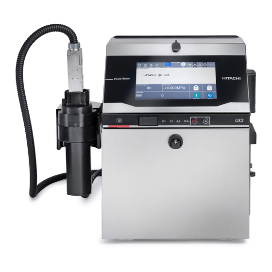
- Page 1 HITACHI Printer Model UX2 Communication User's Manual (Common) ● Before using the printer, thoroughly read this communication user's manual for optimum printer use. ● After reading this communication user's manual, properly keep it for future reference.
- Page 2 August 2022 (rev. B) ● No part of this manual may be copied or reproduced without permission. ● The contents of this manual are subject to change without notice for improvement. All Right Reserved, Copyright © 2022, Hitachi Industrial Equipment Systems Co., Ltd...
-
Page 3: Table Of Contents
Contents 1.Communication overview ..............................3 1.1 Overview ..................................3 1.1.1 Serial communication ............................3 1.1.2 Ethernet communication (Tunnel communication) ..................3 1.1.3 Ethernet communication (Modbus communication) ..................3 1.1.4 Ethernet communication (OPC-UA communication) .................. 3 1.1.5 Ethernet communication (EtherNet/IP communication) ................3 1.2 Configuration diagram ............................... -
Page 4: Communication Overview
1.Communication overview 1.1 Overview 1.1.1 Serial communication The functions described in this document are used to transmit printings and their registration numbers and enter them into the IJ printer with an external device connected to the IJ printer via an RS-232C serial communication line. Connect the USB serial converter to the USB port of the IJ printer and use RS-232C serial communication via the USB serial converter. -
Page 5: Configuration Diagram
1.2 Configuration diagram 1.2.1 Serial communication RS-232C Cable USB Serial Converter External unit IJ Printer 1.2.2 Ethernet communication External unit Ethernet IJ Printer Standard specifications Item Specifications Ethernet standards IEEE802.3, 10BASE-T, 100BASE-T Protocol TCP/IP Connection cable Category 5 UTP or STP cable 1.3 Configuration diagram ●... -
Page 6: Connection Preparations
2.Connection preparations 2.1 Serial communication connection Connect the external communication and the IJ printer by RS-232C serial communication. To connect to serial communication, a USB⇔serial communication conversion cable is required. 2.1.1 USB⇔serial communication conversion cable connection USB⇔Serial communication conversion cable connection port 【Notes on replacement】... -
Page 7: Ethernet Communication Connection
2.2 Ethernet communication connection ● If connecting the IJ Printer with external unit, use a LAN connection cable. 2.2.1 Network connection preparations (1) Connect to inter-office LAN Task Remarks You should obtain the IP address from the Information Systems Department of your company. You should consult with the Information Systems Department of your company concerning network settings such as gateway. -
Page 8: Lan Cable Connection
2.2.3 LAN cable connection Connect the LAN cable 【Notes on replacement】 ● Be sure to turn off the main power when replacing. ● Connect the connectors securely. ■Glossary Terminology Explanation The IP address is a 32-bit ID number allotted to equipment connected to the Internet. -
Page 9: Connection Test
3. Connection test Directly connect the IJ Printer to a PC and check the connection. 3.1 Procedure for connection test 1 Directly connect the IJ Printer to the PC with a LAN cable. 2 Set the network settings of external unit by steps2 to 5. Click the Start menu, and double-click [Windows System] >... - Page 10 4 Click [Internet Protocol Version 4 (TCP/IPv4)]. 5 Select [Use the following IP address], and enter an IP address other than 192.168.0.1 and 192.168.0.255 (the example shown in the figure uses 192.168.0.15) and then enter 255.255.255.0 in the Subnet mask field. Click [OK].
- Page 11 6 Follow the steps below to confirm that the network connection is properly established. The following steps describe procedures for Windows 10. Select [Start Menu] > [Windows System] > [Command prompt] to open the Command Prompt window. Type the following command: Ping 192.168.0.1 Note: This command is not case sensitive.
-
Page 12: Setting The Communication Environment
4. Setting the communication environment 4.1 Setting the communication environment (1) Overview Setting item of Serial communication Function Description Default Comm. port Offline mode when the power is turned on. is OFF Comm. port State at Online mode when the power is turned on. Comm. - Page 13 Setting item of LAN communication Function Description Default No use LAN function cannot be used. Tunnel communication Tunnel communication function can be used Tunnel communication (Output) Only communication of Special communication function A can be used as Tunnel communication Function No use function.
- Page 14 (2) Operating procedure Press Communication environment setup from the setup menu. The "Communication environment setup" screen appears. Change the on-line or off-line Setting item of LAN communication Next Press The second screen appears.
-
Page 15: Communication Monitor
5. Communication Monitor 5.1 Communication Monitor Function ● The contents of serial communications between the external device and IJ printer are displayed. ● Up to 3,000 bytes of data can be acquired at a time. ● When you press the Start , the system erases monitored data and acquires new data. 【Notes on communication monitor】...