Mitsubishi Electric AE-200A Installation Manual
Hide thumbs
Also See for AE-200A:
- Instruction book (192 pages) ,
- Service handbook (108 pages) ,
- Installation manual (40 pages)
Table of Contents
Air Conditioning Control System
Centralized Controller
AE-200A/AE-50A
AE-200E/AE-50E
or
CAUTION, depending on the severity
of possible consequences that may result
when the instructions are not followed
exactly as stated.
Proper installation is important for your
safety and proper functioning of the units.
Thoroughly read the following safety
precautions prior to installation.
Before installing the controller, please read this Installation Manual carefully to ensure proper operation.
Retain this manual for future reference.
Contents
1. Safety precautions ..............................................................2
1-1. General precautions ...................................................................2
1-2. Precautions for unit installation ...................................................3
1-3. Precautions for electrical wiring ..................................................3
1-4. Precautions for relocating or repairing the unit ...........................4
1-5. Additional precautions .................................................................4
2. Introduction .........................................................................6
2-1. Part names .................................................................................6
3. Package contents ...............................................................8
4. Specifications ....................................................................10
4-1. Product specifications ...............................................................10
4-2. External dimensions .................................................................11
5. System configuration ........................................................12
5-1. System configuration example ..................................................12
5-2. Number of connectable units ....................................................16
5-3. Setting M-NET address for various devices ..............................17
5-4. M-NET system setting example ................................................19
6. Installation .........................................................................21
6-1. Installation methods ..................................................................21
6-2. Items not included .....................................................................22
6-3. Items sold separately ................................................................22
6-4. M-NET transmission cable length .............................................23
6-5. Installation space ......................................................................24
6-6. Installation procedures ..............................................................24
7. Wiring connections ...........................................................27
7-1. Removing/reinstalling the service cover ...................................27
cables .......................................................................................27
7-3. Connecting the LAN cable ........................................................29
8. Initial settings ....................................................................30
9. Test run .............................................................................31
9-1. Collective operation ON/OFF ....................................................31
10. External input/output .........................................................32
10-1. External signal input function ..................................................32
10-2. External signal output function ................................................35
11. Inspection and maintenance .............................................36
Installation Manual
Table of Contents

Related Manuals for Mitsubishi Electric AE-200A


Summary of Contents for Mitsubishi Electric AE-200A
-
Page 1: Table Of Contents
Air Conditioning Control System Centralized Controller AE-200A/AE-50A AE-200E/AE-50E Installation Manual Contents 1. Safety precautions ..............2 1-1. General precautions ..............2 1-2. Precautions for unit installation ...........3 1-3. Precautions for electrical wiring ..........3 1-4. Precautions for relocating or repairing the unit ......4 1-5. -
Page 2: Safety Precautions
1. Safety precautions ►Thoroughly read the following safety precautions prior to installation. ►Observe these precautions carefully to ensure safety. ►After reading this manual, pass the manual on to the end user to retain for future reference. ►The user should keep this manual for future reference and refer to it as necessary. This manual should be made available to those who repair or relocate the units. -
Page 3: Precautions For Unit Installation
Properly install all required covers to keep moisture and dust out of the controller. Dust accumulation and the presence of water may result in electric shock, smoke, or fire. To reduce the risk of frostbite, burns, injury, or electric shock, keep the equipment out of the reach of children. -
Page 4: Precautions For Relocating Or Repairing The Unit
Properly secure the cables in place and provide adequate slack in the cables so as not to stress the terminals. Improperly connected cables may break, overheat, and cause smoke or fire. To reduce the risk of injury or electric shock, switch off the main power before performing electrical work. - Page 5 To prevent unauthorized access, always use a security device such as a VPN router when connecting to the Internet. Take appropriate measures against electrical noise interference when installing the controller in hospitals or radio communication facilities. Inverter, high-frequency medical, or wireless communication equipment as well as power generators may cause the air conditioning system to malfunction.
-
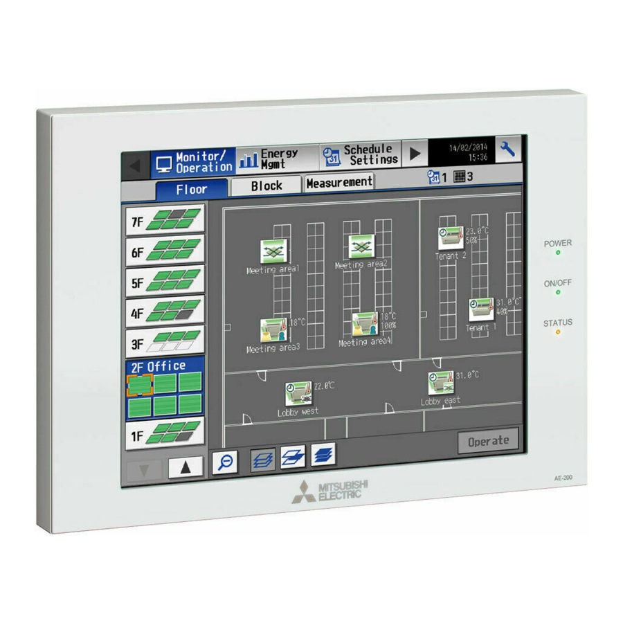
Page 6: Introduction
Any connected air conditioning systems can be operated or monitored on the AE-200A/AE-50A/AE-200E/AE-50E’s LCD or the Web browser. Each AE-200A/AE-50A/AE-200E/AE-50E can control up to a total of 50 indoor units and other equipment. By connecting AE-200A/AE-200E (main controller) and AE-50A/AE-50E (sub controllers), up to 200 indoor units and other equipment can be controlled. - Page 7 * Back side with the service cover removed L/L1 N/L2 LAN1 Connects to other units of equipment over the LAN via a HUB. LAN2 Unused CN7 (Pulse Input) Unused CN6 (RS-422/485) Unused CN4 (RS-232C) Unused CN5 (External I/O) Connects to an external input/output adapter PAC-YG10HA-E. TB3 (M-NET A, B, S) (M3.5) M-NET transmission terminal block Connects to M-NET transmission cables from the outdoor unit.
-
Page 8: Package Contents
3. Package contents The following items are included in the package. Package contents Qty. Centralized controller (AE-200 or AE-50) * A specified SD card is already installed. * A screw is attached at the bottom. Plate A Plate B Roundhead screw (M4 × 40) *1, 2 Roundhead screw (M4 ×... - Page 9 Notes on the SD card installed on the AE-200/AE-50 ● The SD card installed on the AE-200/AE-50 has been set up at the factory. Do not use other SD cards as proper functioning cannot be guaranteed. ● The SD card installed on the AE-200/AE-50 differs from the ones sold on the market. ●...
-
Page 10: Specifications
4. Specifications 4-1. Product specifications Item Specifications Rated input 100–240 VAC ± 10%; 0.21–0.12 A 50/60 Hz Single-phase Power supply Fuse 250 VAC 6.3 A Time-Lag type (IEC 60127-2S.S.5) No specifications M-NET power feeding capability * Only an MN converter can be connected. Operating temperature 0°C –... -
Page 11: External Dimensions
4-2. External dimensions * The dimensions of AE-200 and AE-50 are the same. 284 (11-5/32) 25 (31/32) 40 (1-9/16) Screw: M4 × 6 Hexagonal hole: 2.5 (width across flat) 246 (9-11/16) 261.2 (10-9/32) 217 (8-35/64) 272.7 (10-47/64) 282.7 (11-1/8) 261.2 (10-9/32) 261.2 (10-9/32) 247 (9-23/32) 252.2 (9-59/64) -
Page 12: System Configuration
5. System configuration 5-1. System configuration example This section explains the examples of the following system configurations. (1) System without connection to an AE-50 controller (controlling 50 or fewer units of equipment) (2) System with connection to one or more AE-50 controllers (controlling more than 50 units of equipment) (3) System with connection to a sub system controller (System in which power is supplied from an outdoor unit) (4) System with connection to a sub system controller (System in which power is supplied from the power supply unit (PAC-SC51KUA)) - Page 13 (1) System without connection to an AE-50 controller (controlling 50 or fewer units of equipment) Indoor unit Local remote controller (MA R/C type) AE-200 Local remote controller (ME R/C type) [000] Advanced HVAC CONTROLLER M-NET transmission cable Outdoor unit (Y) MA remote controller cable M-NET [051]...
- Page 14 (2) System with connection to one or more AE-50 controllers (controlling more than 50 units of equipment) Indoor unit Local remote controller (MA R/C type) Local remote controller (ME R/C type) Advanced HVAC CONTROLLER M-NET transmission cable Numbers in parentheses indicate address numbers.
- Page 15 (3) System with connection to a sub system controller (System in which power is supplied from an outdoor unit) Indoor unit Local remote controller (MA R/C type) Local remote controller (ME R/C type) Sub system controller AE-200 [000] Advanced HVAC CONTROLLER M-NET transmission cable Outdoor unit (Y) MA remote controller cable...
-
Page 16: Number Of Connectable Units
(4) System with connection to a sub system controller (System in which power is supplied from the power supply unit (PAC-SC51KUA)) Indoor unit Local remote controller (MA R/C type) Local remote controller (ME R/C type) Sub system controller Power supply unit AE-200 PAC-SC51KUA Advanced HVAC CONTROLLER... -
Page 17: Setting M-Net Address For Various Devices
5-3. Setting M-NET address for various devices Designate the address for each M-NET device. The addresses cannot be overlapped within the same M-NET system. Address setting method M-NET address Assign the lowest address to the main indoor unit in the group, and Indoor unit assign sequential addresses to the rest of the indoor units in the 1–50... - Page 18 [Main and Sub system controllers (M-NET)] Each group can be controlled by a Main system controller or a Sub system controller. AE-200/AE-50 is exclusively for use as a Main system controller and cannot be used as a Sub system controller. Main system controller Main system controller refers to a system controller that controls all other system controllers including the units they control.
-
Page 19: M-Net System Setting Example
5-4. M-NET system setting example (1) Setting example for connecting one or more AE-50 controllers Numbers in parentheses indicate address numbers. AE-200 (Main system controller) M-NET LAN1 IP: 192.168.1.1 50 indoor units [000] ON/OFF remote controller Power supply unit (Sub system controller) (PAC-SC51KUA) [201] Switching... - Page 20 (3) Setting example for controlling Mr. Slim units (A-control models) AE-200 (Main system controller) 20 indoor units Groups 1–20 [000] 2 M-NET adapters Mr. Slim outdoor units (adapter address 21 and 22) Groups 21 and 22 ● An M-NET adapter (sold separately) is required to connect the Mr. Slim model of units to the M-NET. ●...
-
Page 21: Installation
6. Installation To reduce the risk of injury or electric shock, switch off the main power before performing electrical work. To avoid malfunction, do not bundle power cables and signal cables together or place them in the same metallic conduit. 6-1. -
Page 22: Items Not Included
6-2. Items not included The following items are required to install the AE-200/AE-50. Items not included Specifications Electrical box (required only for installation Model: PAC-YG84UTB-J method 2) Metal control box Must be suitable for the AE-200/AE-50 installation. (required only for installation Minimum metal thickness when using installation method 4: 200 mm (7-7/8 in) methods 3 and 4) Locknuts and bushing... -
Page 23: M-Net Transmission Cable Length
6-4. M-NET transmission cable length Observe the maximum total length of M-NET transmission cables to ensure proper signal transmission to and from the connected equipment over the M-NET transmission cables. If the maximum total length is exceeded, the M-NET signals will be attenuated, resulting in communication error and control failure. ●... -
Page 24: Installation Space
6-5. Installation space Leave a space around the AE-200/AE-50 as shown in the figure below. Unit: mm (in) 30 (1-3/16) 284 (11-5/32) 40 (1-37/64) Note ● When installing two or more AE-200/AE-50 controllers side-by-side, leave a space of at least 30 mm (1-3/16 in) between them. - Page 25 6-6-2. Wall-embedded installation (Method 1) Plate B (supplied) * Not used when installing on a board wall. Roundhead screw (M4 × 10) (supplied) Wall Plate A (supplied) * Not used when installing on a board wall. Roundhead screw (M4 × 40) L-shaped driver (supplied) (supplied)
- Page 26 6-6-4. Installation on a metal control box (Method 3) Metal control box Plate A (not supplied) (supplied) L-shaped driver (supplied) Roundhead screw (M4 × 10) (supplied) Roundhead screw (M4 × 40) Plate B (supplied) (supplied) WT07137X01...
-
Page 27: Wiring Connections
7. Wiring connections 7-1. Removing/reinstalling the service cover Unscrew the fixing screw on the service cover and unhook the hooks to remove it as shown in the figure below. To replace the service cover, hook the hooks and screw the fixing screw back in. Note ●... - Page 28 (2) System with connection to one or more AE-50 controllers (controlling more than 50 units of equipment) AE-200 Outdoor unit Overcurrent breaker M-NET transmission cables Earth leakage breaker for centralized control Power supply 100–240 VAC 50/60 Hz AC power cables (Polarized) Cable tie AE-50 Overcurrent breaker...
-
Page 29: Connecting The Lan Cable
7-3. Connecting the LAN cable Connect the LAN cable to the LAN1 port on the AE-200/AE-50. (The LAN2 port is unused.) ● The LAN cable is not supplied. Use a category 5 or above straight LAN cable. ● Use a switching HUB. ●... -
Page 30: Initial Settings
8. Initial settings Initial settings need to be made for each AE-200 on the AE-200’s LCD or the Web browser. The table below explains how to make initial settings on the AE-200’s LCD. Details about the initial settings are covered in the AE-200 Instruction Book and the Instruction Book (Web Browser for Initial Settings). The startup and initial setting procedures vary with the system configuration. -
Page 31: Test Run
9. Test run 9-1. Collective operation ON/OFF Confirm that the group settings and interlock settings are complete before performing a test run. It may take approximately five minutes from power on until the local remote controllers become operable. Refer to the indoor unit Installation Manual for details about a test run. Test run procedure (1) Turn on the power to the AE-200 and all units. -
Page 32: External Input/Output
10. External input/output To use external input/output, a separately-sold external input/output adapter (PAC-YG10HA-E) is required. Note ● When using AE-50, connect the external input/output adapter to each AE-200/AE-50. ● Set the [External Input Setting] setting for each AE-200/AE-50 on the [Network] screen. 10-1. - Page 33 (3) Level signal and pulse signal (A) Level signal Contact ON Contact ON Emergency Contact OFF Contact OFF stop Normal Stop Normal Stop How the demand level is determined Demand level signal specification: When higher levels’ contacts turn on, lower levels’ contacts also stay on. Contact No.5 No.6...
- Page 34 (5) Recommended circuit (A) Level signal Use relays X1, X2, Y1, and Y2 that meet the External power supply (12 or 24 VDC) following specifications. Demand level 4 Gray Demand level 3 Blue Contact rating Yellow Demand level 2 Rated voltage: 12 VDC or above ON/OFF or Emergency Orange stop...
-
Page 35: External Signal Output Function
10-2. External signal output function An ON signal is output when one or more units are in operation, and an Error signal is output when one or more units are in error. (1) External signal output specifications Lead wire from Signal PAC-YG10HA-E No. -
Page 36: Inspection And Maintenance
11. Inspection and maintenance Air conditioning units including AE-200/AE-50 controllers may be damaged after long use, resulting in a performance drop or the units becoming a safety hazard. To use them safely and maximize their lives, it is recommended that a maintenance contract with a dealer or qualified personnel be signed. - Page 37 SD and SDHC Logos are trademarks of SD-3C, LLC. Java is a registered trademark of Oracle and/or its affiliates. This equipment has been tested and found to comply with the limits for a Class B digital device, pursuant to Part 15 of the FCC Rules.
- Page 38 WT07137X01...
- Page 39 WT07137X01...
- Page 40 This product is designed and intended for use in the residential, commercial and light-industrial environment. The product at hand is based on the following EU regulations: • Low Voltage Directive 2006/95/EC • Electromagnetic Compatibility Directive 2004/108/EC • Restriction of Hazardous Substances 2011/65/EU Please be sure to put the contact address/telephone number on this manual before handing it to the customer.