Table of Contents
Quick Links
Table of Contents
Troubleshooting

Related Manuals for Mitsubishi Electric AJ65VBTCU-68DAVN


Summary of Contents for Mitsubishi Electric AJ65VBTCU-68DAVN
- Page 1 Digital-Analog Converter Module type AJ65VBTCU-68DAVN User's Manual...
-
Page 3: Safety Precautions
SAFETY PRECAUTIONS (Read these precautions before using this product.) Before using this product, please read this manual and the relevant manuals introduced in this manual carefully and pay full attention to safety to handle the product correctly. The precautions given in this manual are concerned with this product. Refer to the user's manual of the CPU module to use for a description of the programmable controller system safety precautions. - Page 4 [Installation Precautions] CAUTION Use the programmable controller in an environment that meets the general specifications in the detailed manual. Failure to do so may result in electric shock, fire, malfunction, or damage to or deterioration of the product. Securely fix the module with a DIN rail or CC-Link connector type metal installation fitting. Not doing so can cause a drop or malfunction.
- Page 5 [Starting and Maintenance Precautions] CAUTION Do not touch any pin while power is on. Doing so will cause malfunction. Shut off the external power supply for the system in all phases before cleaning the module. Failure to do so may cause the module to fail or malfunction. Do not disassemble or modify the modules.
- Page 6 CONDITIONS OF USE FOR THE PRODUCT A - 4 A - 4...
-
Page 7: Revisions
This manual confers no industrial property rights or any rights of any other kind, nor does it confer any patent licenses. Mitsubishi Electric Corporation cannot be held responsible for any problems involving industrial property rights which may occur as a result of using the contents noted in this manual. -
Page 8: Table Of Contents
INTRODUCTION Thank you for purchasing the MELSEC-A series programmable controllers. Before using this product, please read this manual carefully and develop familiarity with the functions and performance of the MELSEC-A series programmable controller to handle the product correctly. Make sure that the end users read this manual. CONTENTS SAFETY PRECAUTIONS .......................... - Page 9 4. SETUP AND PREPARATION BEFORE OPERATION 4- 1 to 4- 25 4.1 Pre-Operation Procedure ......................... 4- 1 4.2 Precautions When Handling ........................4- 1 4.3 Name of Each Part ........................... 4- 3 4.4 Concept of Mode Select Switch Setting (Selection of Remote Device Station Compatible Version) ... 4- 6 4.5 Offset/Gain Setting ...........................
-
Page 10: About Manuals
ABOUT MANUALS The following manuals are also related to this product. Order each manual as needed, referring to the following list. Relevant manuals Manual number Manual name (model code) CC-Link System Master/Local Module Type AJ61BT11/A1SJ61BT11 User's Manual IB-66721 System configuration, performance specifications, functions, handling, wiring, and troubleshooting of the (13J872) AJ61BT11 and A1SJ61BT11 (Sold separately) -
Page 11: About The Generic Terms And Abbreviations
ABOUT THE GENERIC TERMS AND ABBREVIATIONS Unless otherwise specified, the following generic terms and abbreviations are used in this manual to describe Type AJ65VBTCU-68DAVN analog-digital converter module. Generic Term/Abbreviation Description GX Developer Product name of the software package for the MELSEC programmable Controllers. -
Page 12: Product Components
PRODUCT COMPONENTS This product consists of the following. Product Name Quantity Type AJ65VBTCU-68DAVN digital-analog converter module Type AJ65VBTCU-68DAVN digital-analog converter module user's manual (hardware) A - 10 A - 10... - Page 13 MEMO A - 11 A - 11...
-
Page 14: Overview
This user's manual explains the specifications, handling, programming methods and others of Type AJ65VBTCU-68DAVN digital-analog converter module (hereafter abbreviated to the " AJ65VBTCU-68DAVN ") which is used as a remote device station of a CC-Link system. The AJ65VBTCU-68DAVN is a module designed to convert digital values (16-bit signed BIN data) from outside the programmable controller into analog values (voltages or currents). -
Page 15: Features
1 OVERVIEW MELSEC-A 1.2 Features This section gives the features of the AJ65VBTCU-68DAVN. (1) High accuracy This module performs D/A conversion at the accuracy of ±0.3% relative to the maximum value of the analog output value at the operating ambient temperature of 0 to 55°C, or at ±0.2% relative to the maximum value of the analog output... - Page 16 1 OVERVIEW MELSEC-A (7) Replacement of module without stopping CC-Link system The use of the online connectors (for communication, for power supply) allows the module to be changed without the CC-Link system being stopped. (8) Improved wiring workability The connectors and setting switches are all front-mounted. This enables connections to be made only by front wiring, improving wiring workability.
-
Page 17: System Configuration
2 SYSTEM CONFIGURATION MELSEC-A 2 SYSTEM CONFIGURATION This chapter describes the system configuration for use of the AJ65VBTCU-68DAVN. 2.1 Overall Configuration The overall configuration for use of the AJ65VBTCU-68DAVN is shown below. (1) Remote net ver. 1 mode 2 - 1... - Page 18 2 SYSTEM CONFIGURATION MELSEC-A (2) Remote net ver. 2 mode, remote net additional mode 2 - 2 2 - 2...
-
Page 19: Applicable System
2 SYSTEM CONFIGURATION MELSEC-A 2.2 Applicable System This section explains the applicable system. (1) Applicable master modules For available master modules, visit the CC-Link Partner Association (CLPA) website at: http://www.cc-link.org/ REMARK Check the specifications of the master module before use. (2) Applicable combinations The following table indicates usability according to the combinations of the master modules, the mode setting and station information (station type) of the GX... -
Page 20: Precautions For System Configuration
2 SYSTEM CONFIGURATION MELSEC-A POINT For use in the remote net ver. 2 mode or remote net additional mode, the master module of QJ61BT11N and the peripheral software package of GX Developer Version 8.03D or later are required. For more information on the applicable modules (CPU modules, network modules) and applicable software packages, refer to the CC-Link System Master/Local Module User's Manual (Details) QJ61BT11N. -
Page 21: Parts Sold Separately
2 SYSTEM CONFIGURATION MELSEC-A 2.4 Parts Sold Separately The plugs for AJ65VBTCU-68DAVN are sold separately. Please purchase them as necessary. Mitsubishi model Part model name Color of Specifications name (manufacturer) the cover Maximum Applicable cable Applicable cable core size rated... - Page 22 2 SYSTEM CONFIGURATION MELSEC-A REMARK The following table indicates the connectors of this module with which the above plugs/connectors are compatible. Connector of This Module Compatible Optional Parts • One-touch connector plug for communication One-touch connector for • Online connector for communication communication •...
-
Page 23: Specification
3 SPECIFICATION MELSEC-A 3 SPECIFICATION This chapter provides the specifications of the AJ65VBTCU-68DAVN. 3.1 General Specification Table 3.1 indicates the general specifications of the AJ65VBTCU-68DAVN. Table 3.1 General specification Item Specification Usage ambient temperature 0 to 55°C Storage ambient temperature -20 to 75°C... -
Page 24: Performance Specification
3 SPECIFICATION MELSEC-A 3.2 Performance Specification Table 3.2 indicates the performance specifications of the AJ65VBTCU-68DAVN. Table 3.2 Performance Specifications Item AJ65VBTCU-68DAVN IP1XB Protection class 16-bit signed binary (-4096 to 4095) Digital input Analog output -10 to 10VDC (external load resistance: 2k to 1M ) -
Page 25: I/O Conversion Characteristics
3 SPECIFICATION MELSEC-A Item AJ65VBTCU-68DAVN 24V DC (20.4V DC to 26.4V DC, ripple factor within 5%) External supply power Inrush current : 6.1A, within 1.2ms Current consumption 0.15A (When 24VDC) Weight 0.16kg *1 For the details of the I/O conversion characteristic, refer to Section 3.3. -
Page 26: Voltage Output Characteristics
3 SPECIFICATION MELSEC-A 3.3.1 Voltage output characteristics The voltage output characteristic graph is shown below. -4096 -4000 -2000 2000 4000 4095 Digital input value Number Analog output Range Setting Offset value Gain value Digital Input value Maximum resolution -10 to 10v -4000 to 4000 2.5mV 0 to 5V... -
Page 27: Relationship Between Offset/Gain Setting And Analog Output Value
3.3.2 Relationship between offset/gain setting and analog output value How to calculate the analog output value: The resolution of AJ65VBTCU-68DAVN can be set arbitrarily by modifying the setting of the offset value and gain value. How to calculate the analog value resolution and the analog output value for a given digital input value when the settings of the offset value and gain value are changed is shown next. -
Page 28: Conversion Speed
Conversion speed indicates time required to read the digital output value written to the buffer memory, perform D/A conversion, and then output the specified analog value. Conversion speed per channel of the AJ65VBTCU-68DAVN is 1ms. Due to the data link processing time of the CC-Link system, there is a transmission delay until the D/A conversion value is read actually. -
Page 29: Function
Section 3.6.5 CPU has entered the STOP status or the AJ65VBTCU-68DAVN has stopped D/A CPU is in the STOP conversion due to error occurrence. status (HOLD/CLEAR... -
Page 30: Combinations Of Various Functions
3 SPECIFICATION MELSEC-A 3.4.1 Combinations of various functions You can set the analog output as indicated in Table 3.4 by combining the Analog output enable/disable setting (RWwm+8), CH. analog output enable/disable flag (RYn0 to RYn7) and HOLD/CLEAR setting (RWwm+B). Make setting according to your system application. Table 3.4 Analog output status combination list Setting Analog output enable/disable... -
Page 31: Remote I/O Signals
This section describes the assignment and functions of the remote I/O signals. 3.5.1 Remote I/O signal list Remote inputs (RX) mean the input signals from the AJ65VBTCU-68DAVN to the master module, and remote outputs (RY) mean the output signals from the master module to the AJ65VBTCU-68DAVN. - Page 32 Table 3.5 indicates the assignment and names of the remote I/O signals for ver. 1 remote device station (ver. 1 compatible slave station) setting. Table 3.5 Remote I/O Signal List for Ver. 1 Remote Device Station (Ver. 1 Compatible Slave Station) Setting Signal Direction: AJ65VBTCU-68DAVN Master Module Signal Direction: Master Module AJ65VBTCU-68DAVN...
- Page 33 Table 3.6 indicates the assignment and names of the remote I/O signals for ver. 2 remote device station (ver. 2 compatible slave station) setting. Table 3.6 Remote I/O Signal List for Ver. 2 Remote Device Station (Ver. 2 Compatible Slave Station) Setting Signal Direction: AJ65VBTCU-68DAVN Master Module Signal Direction: Master Module AJ65VBTCU-68DAVN...
-
Page 34: Functions Of The Remote I/O Signals
(turned off) by the error reset request flag. PROM write error flag RXnC At occurrence of this error, power on the AJ65VBTCU-68DAVN again. If this flag turns on after the power is switched on again, it is a hardware fault. Contact your nearest Mitsubishi representative. - Page 35 3 SPECIFICATION MELSEC-A Table 3.7 Remote I/O Signal Details (2/2) Device No. Signal Name Description D/A conversion value output enable flag for channel 1 to 8. Turn on this flag to enable RYn0 analog output the D/A conversion value of the corresponding channel to be output. enable/disable flag Turn off when you want to disable the output of the D/A conversion value.
-
Page 36: Remote Register
The remote register allocation and data structures are described below. 3.6.1 Allocation of the remote register The number of data of the AJ65VBTCU-68DAVN differs between ver. 1 remote device station (ver. 1 compatible slave station) setting and ver. 2 remote device station (ver. 2 compatible slave station) setting. - Page 37 The address set for the master station in the station number setting. POINT Do not execute read or write to the remote register that is not allowed to use. When a read or write is executed, the functions of the AJ65VBTCU-68DAVN is not guaranteed. 3 - 15...
-
Page 38: Digital Value Setting (Addresses Rwwm+0 H To Rwwm+7 H )
3 SPECIFICATION MELSEC-A 3.6.2 CH. digital value setting (Addresses RWwm+0 to RWwm+7 (1) This area is used to write the digital value for the D/A conversion from the programmable controller CPU. (2) The digital value at all channels become “0” in the following conditions: (a) After the power is turned on, when the remote READY (RX(n+1)B) is turned (3) The digital value that may be set is a 16-bit signed binary within the setting range which matches the output range setting. -
Page 39: Output Range Setting
3 SPECIFICATION MELSEC-A 3.6.4 CH. output range setting (Address RWwm+9 , RWwm+A (1) Set the analog output range per channel. (2) Operation is performed according to the setting made for the leading edges of initial data setting request flag (RY(n+9)). (3) The default settings are -10 to 10V for all channels. -
Page 40: Check Code (Addresses Rwrn+0 H To Rwrn+7 H )
If an error occurs (the RUN LED flickers) when data is written to the AJ65VBTCU- 68DAVN, the corresponding error code is stored into the remote register (address RWrn+8 ) of the AJ65VBTCU-68DAVN. Refer to Section 6.1 for details of the error codes. 3 - 18... - Page 41 3 SPECIFICATION MELSEC-A MEMO 3 - 19 3 - 19...
-
Page 42: Setup And Preparation Before Operation
Start data link. Offset/gain setting (Refer to Section 4.5.) 4.2 Precautions When Handling The precautions when handling the AJ65VBTCU-68DAVN are described below: Do not touch any terminal while power is on. Doing so may cause malfunction. CAUTION Prevent foreign matter such as dust or wire chips from entering the module. - Page 43 (width 41)-dedicated fitting. (a) CC-Link connector type metal installation fitting model A6PLT-J65V1 (3) Refer to the Master Module user's manual for the name, specification, and manufacturers of supported cables for the use with AJ65VBTCU-68DAVN. 4 - 2 4 - 2...
-
Page 44: Name Of Each Part
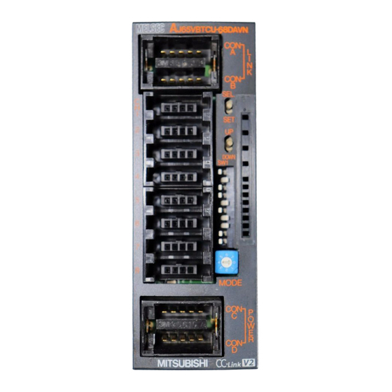
4 SETUP AND PREPARATION BEFORE OPERATION MELSEC-A 4.3 Name of Each Part The name of each part in the AJ65VBTCU-68DAVN is shown. [Pin layout and signals name] Pin arrangement Pin No. Signal name J65VBTCU-68DAVN CONA, B CH1 V+ POWER CON1... - Page 45 Used to adjust the offset value and gain value of the channel specified by the SELECT/SET switch. switch The switch to be used for selecting the mode among Ver. remote device station (Ver. -compatible slave station)/Normal mode/Test mode AJ65VBTCU-68DAVN 0: Normal mode Mode select Ver.1 remote device station 1: Test mode (User range setting 1) switch (Ver.1-compatible slave station)
- Page 46 4 SETUP AND PREPARATION BEFORE OPERATION MELSEC-A Name and Number Description appearance Use the switches in STATION NO. "10", "20" and "40" to set the tens of the station number. Use the switches in STATION NO. "1", "2", "4" and "8" to set the units of the station number. The switches are all factory-set to OFF.
-
Page 47: Concept Of Mode Select Switch Setting (Selection Of Remote Device Station Compatible Version)
4.4 Concept of Mode Select Switch Setting (Selection of Remote Device Station Compatible Version) The AJ65VBTCU-68DAVN must be handled after setting of the remote device station version according to the configuration of the used CC-Link system. There are the following remote device stations. - Page 48 4 SETUP AND PREPARATION BEFORE OPERATION MELSEC-A (2) Applicable combinations and setting concepts The following table indicates usability according to the combinations of the master modules, the mode setting and station information (station type) of the GX Developer network parameters, and the mode select switch setting of the module.
-
Page 49: Offset/Gain Setting
4 SETUP AND PREPARATION BEFORE OPERATION MELSEC-A 4.5 Offset/Gain Setting When changing the I/O conversion characteristics, follow the procedure below. START Move the SELECT/SET switch to "SET". Release your hand after making sure that the "RUN" LED has turned on . Set the mode select switch as indicated below. - Page 50 (4) When making offset/gain setting (in the test mode), set any of the following test modes with the mode select switch. AJ65VBTCU-68DAVN (Ver. 1 remote device station): 1, 2 AJ65VBTCU-68DAVN (Ver. 2 remote device station): 4, 5 The user range settings 1 selected with the mode select switch set to 1 and 4 are the same.
-
Page 51: Section Number Setting
For details, refer to the user's manual of the master module used. 4.7 Facing Direction of the Module Installation The AJ65VBTCU-68DAVN module may be installed in any of six orientations using a DIN rail or CC-Link connector type fitting. (There are no restrictions on the facing directions.) -
Page 52: Data Link Cable Wiring
4 SETUP AND PREPARATION BEFORE OPERATION MELSEC-A 4.8 Data Link Cable Wiring This section explains the wiring of the CC-Link dedicated cable used for connection of the AJ65VBTCU-68DAVN and master module. 4 - 11 4 - 11... -
Page 53: Connection Of The Cc-Link Dedicated Cables
4 SETUP AND PREPARATION BEFORE OPERATION MELSEC-A 4.8.1 Connection of the CC-Link dedicated cables Connect the CC-Link dedicated cable between the AJ65VBTCU-68DAVN and master module as shown below. 4 - 12 4 - 12... -
Page 54: How To Connect Connectors
4 SETUP AND PREPARATION BEFORE OPERATION MELSEC-A POINT • On this unit, use the Ver. 1.10-compatible CC-Link dedicated cable (FANC- 110SBH, CS-110, FA-CBL200PSBH). You cannot use the Ver. 1.10-compatible CC-Link dedicated cables of other than the above types, CC-Link dedicated cables and CC-Link dedicated, high- performance cables. -
Page 55: Wiring
4 SETUP AND PREPARATION BEFORE OPERATION MELSEC-A 4.9 Wiring This section provides the instructions for wiring the AJ65VBTCU-68DAVN and its wiring with external equipment. 4.9.1 Wiring precautions To obtain maximum performance from the functions of AJ65VBTCU-68DAVN and improve the system reliability, an external wiring with high durability against noise is required. -
Page 56: Wiring Of Module With External Equipment
4 SETUP AND PREPARATION BEFORE OPERATION MELSEC-A 4.9.2 Wiring of module with external equipment Motor drive unit or like CH.1 CON1 CH.1 V+ conversion CH.1 COM Motor drive unit or like CH.8 CON8 CH.8 V+ CH.8 COM 1 Use a two-core twist shielded line for the wiring. 2 If noise or ripples occur in the external wiring, connect a 0.1 to 0.47µF capacitor (25V or higher voltage-resistant product) to the input terminals of the external device. -
Page 57: How To Wire The One-Touch Connector Plug
This section describes the way to wire the one-touch connector plug. Refer to section 2.4 for more information on the types and specifications of the one- touch connector plugs which conform to the AJ65VBTCU-68DAVN. 4.10.1 Precautions for the transition wiring of the one-touch connector for power supply and When the power supply is connected in the transition wiring with the one-touch connector for power supply and FG, a current flows in the inside of the module. - Page 58 4 SETUP AND PREPARATION BEFORE OPERATION MELSEC-A Power supply port name Power supply port Maximum rated current One-touch connector for power supply and FG (CONC-2, 3 1) Module power supply (IN) pin) Power supplied by the Maximum consumption Description of the power supplies power supply port current Refer to the external...
-
Page 59: Wiring Procedures For The One-Touch Connector
4 SETUP AND PREPARATION BEFORE OPERATION MELSEC-A 4.10.2 Wiring procedures for the one-touch connector The following are the wiring procedures for the one-touch connector. Plug cover 1) Check the connector. Plug body Check that the plug cover is attached to the plug body. Note: Do not push the plug cover into the plug body. - Page 60 4 SETUP AND PREPARATION BEFORE OPERATION MELSEC-A (From the previous page) 4) Set the plug cover. After inserting the cable, put down the plug cover so that its face is horizontal to the plug surface, allowing the metal contacts to be fitted into the plug cover. Metal contacts 5) Press the center part of the plug cover.
- Page 61 4 SETUP AND PREPARATION BEFORE OPERATION MELSEC-A (From the previous page) [Correct example] 8) Check the press-fit condition (viewing from the top). Viewing from the top, check that there is no clearance between the plug body and plug cover. Note: Clearance may occur between the plug body and plug cover when the latches do not engage securely as shown in [Wrong example].
-
Page 62: Wiring Procedures For The One-Touch Connector For Communication
4 SETUP AND PREPARATION BEFORE OPERATION MELSEC-A 4.10.3 Wiring procedures for the one-touch connector for communication This section provides the wiring procedures of the one-touch connector for communication. 1) Check the connector. Check that the plug cover is attached to the plug body. Note: Do not push the plug cover into the plug body. - Page 63 4 SETUP AND PREPARATION BEFORE OPERATION MELSEC-A (From the previous page) Pliers 6) Press both ends of the plug cover Latches After pressing the center part of the plug cover, press both ends of the plug cover where latches are located. Verify that the latches engage with the plug body.
-
Page 64: Wiring Procedures For The One-Touch Connector For Power Supply And Fg
4 SETUP AND PREPARATION BEFORE OPERATION MELSEC-A 4.10.4 Wiring procedures for the one-touch connector for power supply and FG The following are the wiring procedures for the one-touch connector used for power supply and FG. Plug body Plug cover 1) Check the connector. Check that the plug cover is attached to the plug body. - Page 65 4 SETUP AND PREPARATION BEFORE OPERATION MELSEC-A (From the previous page) [Correct example] 6) Check the press-fit condition (viewing from the wiring side). Viewing from the wiring side, check that the plug surface is flush with the plug cover. Set the plug cover so that it protrudes 0.2mm or less from the plug surface.
-
Page 66: Maintenance And Inspection
MELSEC-A 4.11 Maintenance and Inspection There are no special inspection items for the AJ65VBTCU-68DAVN module, but follow the inspections items describes in the programmable controller CPU User's Manual so that the system can always be used in the best condition. -
Page 67: Programming
5 PROGRAMMING The programming procedure, basic read/write programs, and program examples for the AJ65VBTCU-68DAVN are described. When utilizing the program example introduced in this chapter for an actual system, fully verify that there are no problems in controllability in the target system. -
Page 68: When Remote Net Ver. 1 Mode Is Used
5.2 When Remote Net Ver. 1 Mode Is Used 5.2.1 Conditions of Program Example The program examples in this section are created under the following conditions. (1) System configuration (2) Relationships between programmable controller CPU, master module and AJ65VBTCU-68DAVN Programmable controller CPU 5 - 2 5 - 2... - Page 69 5 PROGRAMMING MELSEC-A POINT Some CPU modules may not accept the devices used in the program example in this chapter. For the setting ranges of the devices, refer to the user's manual of the CPU module used. For the A1SCPU, for example, devices X100, Y100 and later are unusable.
-
Page 70: Program Example For Use Of The Qcpu (Q Mode)
5 PROGRAMMING MELSEC-A 5.2.2 Program Example for Use of the QCPU (Q mode) The program examples in this section are created under the following conditions. GX Developer is used to set the network and automatic refresh parameters. Using the remote device station initialization procedure registration function facilitates initial settings. - Page 71 (b) Setting the procedure registration When the initial data processing request flag (RX18) turns on and the remote device station initialization procedure registration (SB0D) is set, the following data are registered to the AJ65VBTCU-68DAVN. Procedure Execution Condition Execution Analog output enable/disable setting: channenls 1, 2: enable (RWw8 :00FC CH.1 to CH.4 output range setting : channel 1: 0 to 5V...
- Page 72 5 PROGRAMMING MELSEC-A (3) Program example Checking of AJ65VBTCU-68DAVN status Reads data link status. AJ65VBTCU-68DAVN data link normal AJ65VBTCU-68DAVN data link abnormal *1, *2 Turns off initialization Initialization procedure registration procedure registration directive. Turns on initialization procedure registration directive. Changing of initial settings...
- Page 73 5 PROGRAMMING MELSEC-A *1 When making remote device station initialization procedure registration to multiple stations, correct the program within the dotted line 1) as shown below. [System configuration] [Corrected program] • RX(m+1)B and RX(n+1)B are remote READY. • RX(m+1)8 and RX(n+1)8 are initial data processing request flags. Insert the remote READY and initial data processing request flags for all the stations, to which the remote device station initialization procedure registration has been made, into the program.
- Page 74 5 PROGRAMMING MELSEC-A [Usage in combination with other remote device stations] (1) Depending on the remote device stations to be used, the program enclosed by the dotted line 1) has two programming patterns as shown in the above and the below figures. (To check which pattern can be used, refer to the manual for the remote device to be used.) [System configuration] [Corrected program]...
- Page 75 5 PROGRAMMING MELSEC-A When using the program enclosed by the dotted line 1) in combination with other remote device stations, correct the program as shown below. [System configuration] [Corrected program] Note that the master module can register the initialization procedure of only the specified station out of the multiple remote device stations.
-
Page 76: Program Example For Use Of The Qnacpu
5 PROGRAMMING MELSEC-A 5.2.3 Program Example for Use of the QnACPU GX Developer is used to set the network and automatic refresh parameters. (1) Parameter setting (a) Network parameter setting (b) Automatic refresh parameter setting POINT When the QnACPU is used, using "Y" as the remote output (RY) refresh device of the automatic refresh parameter may not hold the analog value even for the HOLD setting. - Page 77 5 PROGRAMMING MELSEC-A (2) Program example 5 - 11 5 - 11...
-
Page 78: Program Example For Use Of The Acpu/Qcpu (A Mode) (Dedicated Instructions)
A sequence program is used to set the network and automatic refresh parameters. (1) Program example Setting of network parameters using RLPA dedicated instruction Synchronization mode invalid Number of connected modules:1 AJ65VBTCU-68DAVN station information (remote device station, 3 station occupied, station No. 1) Dedicated instruction (RLPA) Starting I/O number of... - Page 79 5 PROGRAMMING MELSEC-A 5 - 13 5 - 13...
- Page 80 5 PROGRAMMING MELSEC-A Setting of digital values CH.1 digital value setting (RWw0) : 500 Digital value setting CH.2 digital value setting (RWw1) : 1000 Analog output enable/disable specification Turns on CH.1 analog output enable/disable flag (RY00). Analog output enable Turns on CH.2 analog output enable/disable flag (RY01).
-
Page 81: Program Example For Use Of The Acpu/Qcpu (A Mode) (From/To Instructions)
5 PROGRAMMING MELSEC-A 5.2.5 Program Example for Use of the ACPU/QCPU (A mode) (FROM/TO instructions) A sequence program is used to set the network parameters. (1) Program example 5 - 15 5 - 15... - Page 82 5 PROGRAMMING MELSEC-A 5 - 16 5 - 16...
-
Page 83: When Remote Net Ver. 2 Mode Is Used
5.3.1 Conditions of program examples The program examples in this section are created under the following conditions. (1) System configuration (2) Relationships between programmable controller CPU, AJ65VBTCU-68ADV and AJ65VBTCU-68DAVN [Remote input (RX), remote output (RY)] 5 - 17 5 - 17... - Page 84 5 PROGRAMMING MELSEC-A [Remote registers (RWw, RWr)] 5 - 18 5 - 18...
- Page 85 (RY00) CH. 2 analog output Enable enable/prohibit flag (RY01) POINT When using the AJ65VBTCU-68DAVN as the ver. 2 remote device station in the normal mode, set the mode select switch to "3". 5 - 19 5 - 19...
-
Page 86: Setting Of Parameters And Initialization Procedure Registration
5 PROGRAMMING MELSEC-A 5.3.2 Setting of parameters and initialization procedure registration The network parameters and automatic refresh parameters are set using GX Developer. Use of the remote device station initialization procedure registration function makes initial setting easy. (1) Parameter setting (a) Network parameter setting (b) Automatic refresh parameter setting POINT... - Page 87 5 PROGRAMMING MELSEC-A (2) Initial setting by remote device station initialization procedure registration function (a) Setting of target station numbers Set the station numbers to which initial setting will be made. Set the target station numbers to "1" and "4". (b) Selection of procedure registration (part 1) Make setting for the AJ65VBTCU-68ADV.
- Page 88 Initial data setting completion flag (RX19) turns ON Initial data setting request flag (RY19) is turned OFF. (g) Setting result (part 2) The following indicates the setting result of the AJ65VBTCU-68DAVN. POINT (1) If the remote device station initialization procedure registration command (SB000D) is turned OFF after initial processing, all RY signals that turned ON in the initial procedure registration turn OFF.
-
Page 89: Program Example
5 PROGRAMMING MELSEC-A 5.3.3 Program example Confirmation of AJ65VBTCU-68ADV, AJ65VBTCU-68DAVN status AJ65VBTCU-68ADV AJ65VBTCU-68DAVN Data link normal AJ65VBTCU-68ADV Data link abnormal AJ65VBTCU-68DAVN Data link abnormal Initialization procedure registration Turns OFF the initialization procedure registration command. Turns ON the initialization procedure registration command. - Page 90 Digital value setting CH. 1 digital value setting (RWw0) :500 CH. 2 digital value setting (RWw1) :1000 AJ65VBTCU-68DAVN Specification of analog output enable/prohibit Turns ON the CH. 1 analog Analog output enable output enable/prohibit flag (RY00). Turns ON the CH. 2 analog output enable/prohibit flag (RY01).
-
Page 91: When Remote Net Additional Mode Is Used
5.4.1 Conditions of program examples The program examples in this section are created under the following conditions. (1) System configuration (2) Relationships between programmable controller CPU, AJ65VBTCU-68ADV and AJ65VBTCU-68DAVN [Remote input (RX), remote output (RY)] 5 - 25 5 - 25... - Page 92 5 PROGRAMMING MELSEC-A [Remote registers (RWw, RWr)] 5 - 26 5 - 26...
- Page 93 (RY00) CH. 2 analog output Enable enable/prohibit flag (RY01) POINT When using the AJ65VBTCU-68DAVN as the ver. 2 remote device station in the normal mode, set the mode select switch to "3". 5 - 27 5 - 27...
-
Page 94: Setting Of Parameters And Initialization Procedure Registration
5 PROGRAMMING MELSEC-A 5.4.2 Setting of parameters and initialization procedure registration The network parameters and automatic refresh parameters are set using GX Developer. Use of the remote device station initialization procedure registration function makes initial setting easy. (1) Parameter setting (a) Network parameter setting (b) Automatic refresh parameter setting POINT... - Page 95 5 PROGRAMMING MELSEC-A (2) Initial setting by remote device station initialization procedure registration function (a) Setting of target station numbers Set the station numbers to which initial setting will be made. Set the target station numbers to "1" and "4". (b) Selection of procedure registration (part 1) Make setting for the AJ65VBTCU-68ADV.
- Page 96 Initial data setting completion flag (RX19) turns ON Initial data setting request flag (RY19) is turned OFF. (g) Setting result (part 2) The following indicates the setting result of the AJ65VBTCU-68DAVN. POINT (1) If the remote device station initialization procedure registration command (SB000D) is turned OFF after initial processing, all RY signals that turned ON in the initial procedure registration turn OFF.
-
Page 97: Program Example
5 PROGRAMMING MELSEC-A 5.4.3 Program example Confirmation of AJ65VBTCU-68ADV, AJ65VBTCU-68DAVN status AJ65VBTCU-68ADV AJ65VBTCU-68DAVN Data link normal AJ65VBTCU-68ADV Data link abnormal AJ65VBTCU-68DAVN Data link abnormal Initialization procedure registration Turns OFF the initialization procedure registration command. Turns ON the initialization procedure registration command. - Page 98 Digital value setting CH. 1 digital value setting (RWw0) :500 CH. 2 digital value setting (RWw1) :1000 AJ65VBTCU-68DAVN Specification of analog output enable/prohibit Turns ON the CH. 1 analog Analog output enable output enable/prohibit flag (RY00). Turns ON the CH. 2 analog output enable/prohibit flag (RY01).
- Page 99 5 PROGRAMMING MELSEC-A MEMO 5 - 33 5 - 33...
-
Page 100: Troubleshooting
6 TROUBLESHOOTING MELSEC-A 6 TROUBLESHOOTING The details of the errors which may occur when using the AJ65VBTCU-68DAVN and troubleshooting are described. 6.1 Error Code List When the data is written from the programmable controller CPU to the master module, and an error occurs (AJ65VBTCU-68DAVN "RUN" LED flashes), the error code is stored to the AJ65VBTCU-68DAVN remote register RWrn+8. -
Page 101: Using The Led Indications To Check Errors
This section explains how to check errors using the LED indications of the AJ65VBTCU-68DAVN. Refer to the programmable controller CPU and master module user's manual for issues regarding the programmable controller CPU and master module. (1) When the AJ65VBTCU-68DAVN "POWER" LED is off Check Item Corrective Action Is 24VDC power on? Check the external power supply. - Page 102 (4) When the AJ65VBTCU-68DAVN "L RUN" LED is off Communications are broken. For details, refer to troubleshooting in the user's manual of the master module used. (5) When the AJ65VBTCU-68DAVN "L ERR." LED flickers at fixed intervals Check item Corrective action Has the station number or transmission speed...
-
Page 103: Troubleshooting For The Case Where The "Err." Led Of The Master Station Flickers
6 TROUBLESHOOTING MELSEC-A 6.3 Troubleshooting for the Case where the "ERR." LED of the Master Station Flickers The "ERR"LED on the master station is flashing Do the parameter setting and the installed system configuration match properly? Revise the parameter settings or installed system configuration Are the master station link special registers... - Page 104 6 TROUBLESHOOTING MELSEC-A Is the "L RUN" LED lit? Are the station number setting switches properly (not overlapping with other stations)? Set the station number setting switches properly Turn on the power again Is the transmission speed setting correct? Set the correct transmission speed Turn on the power again Is the communication cable wired properlly...
-
Page 105: Appendices
Models (1) Comparison between AJ65VBTCU-68DAV and AJ65VBTCU- 68DAVN The following table indicates the comparison between the AJ65VBTCU-68DAV and AJ65VBTCU-68DAVN. Comparison between AJ65VBTCU-68DAV and AJ65VBTCU-68DAVN Item AJ65VBTCU-68DAV AJ65VBTCU-68DAVN • Ver. 1 remote device station (ver. 1 compatible slave station) or Ver. 1 remote device station (ver. 1 compatible... - Page 106 (3) Compatibility between AJ65VBTCU-68DAV and AJ65VBTCU- 68DAVN There is compatibility when the AJ65VBTCU-68DAVN is used as the ver. 1 remote device station in the existing system. (Refer to Section 4.4 for details.) When the AJ65VBTCU-68DAV is replaced by the AJ65VBTCU-68DAVN in the existing system, the replacement can be made without the programs being modified since the remote I/O signals, remote registers, etc.
-
Page 107: Appendix 2 External Dimension Diagram
APPENDICES MELSEC-A Appendix 2 External dimension diagram The outline dimension drawing of the AJ65VBTCU-68DAVN is shown below. 3.5 (0.14) 31 (1.22)* 67 (2.64) 41 (1.61) 16.5 (0.65) J65VBTCU-68DAVN PO W ER L RUN DOWN L ERR TEST O FFS ET... -
Page 108: Index
INDEX Absolute maximum output ......3-2 Gain value ............3-3 Accuracy............ 3-2,3-5 General specification ........3-1 Allocation of the remote register ....3-14 Analog output ..........3-2 Analog output enable/disable flag ....3-13 HOLD/CLEAR setting ........3-17 Analog output enable/disable setting ... 3-16 Analog output status combination list..... - Page 109 Program example for use of the ACPU/QCPU (A mode)(FROM/TO instructions)....5-15 Program example for use of the QCPU(Q mode) (when remote net ver. 1 mode is used)..5-1 Program example for use of the QnACPU... 5-10 Programming procedure ......... 5-1 Remote device station.......
- Page 110 WARRANTY Please confirm the following product warranty details before using this product. 1. Gratis Warranty Term and Gratis Warranty Range If any faults or defects (hereinafter "Failure") found to be the responsibility of Mitsubishi occurs during use of the product within the gratis warranty term, the product shall be repaired at no cost via the sales representative or Mitsubishi Service Company.
- Page 112 SH(NA)-080402E-G(2207)MEE MODEL: AJ65V-68DAN-U-SY-E MODEL CODE: 13JR66 HEAD OFFICE : TOKYO BUILDING, 2-7-3 MARUNOUCHI, CHIYODA-KU, TOKYO 100-8310, JAPAN NAGOYA WORKS : 1-14 , YADA-MINAMI 5-CHOME , HIGASHI-KU, NAGOYA , JAPAN When exported from Japan, this manual does not require application to the Ministry of Economy, Trade and Industry for service transaction permission.