Mitsubishi Electric AE-200A Instruction Book
Air conditioning control system centralized controller
Hide thumbs
Also See for AE-200A:
- Instruction book (192 pages) ,
- Service handbook (108 pages) ,
- Installation manual (40 pages)
Table of Contents
Quick Links
Air Conditioning Control System
Centralized Controller
AE-200A/AE-50A
AE-200E/AE-50E
Before using the controller, please read this Instruction Book carefully to ensure proper operation.
Retain this manual for future reference.
Contents
1. Safety precautions ..............................................................4
1-1. General precautions ..............................................................4
1-2. Precautions for relocating or repairing the unit .....................5
1-3. Additional precautions ...........................................................5
2. Introduction .........................................................................6
2-1. Terms used in this manual ....................................................6
2-2. Required licenses ..................................................................6
2-3. "Group", "Block", and "EM block" definitions .........................6
2-4. Main and Sub system controllers (M-NET) ...........................7
2-5. Controller interface ................................................................8
2-6. Number of connectable units ................................................9
2-7. Product features ....................................................................9
3. Basic operations ............................................................... 11
3-1. Monitor/Operation ............................................................... 11
3-2. Energy Management ...........................................................29
3-3. Schedule .............................................................................47
3-4. Status List ...........................................................................58
3-5. Malfunction Log ...................................................................61
3-6. Error code list ......................................................................62
4. Practical operations ..........................................................66
4-1. Maintenance ........................................................................66
5. Maintenance .....................................................................74
5-1. Backing up settings data .....................................................74
5-2. Importing settings data ........................................................75
5-3. CSV output ..........................................................................76
5-4. Touch Panel Calibration ......................................................83
5-5. Software information ...........................................................83
5-6. Cleaning the touch panel ....................................................84
6. Specifications ....................................................................85
Appendix: Added functions .....................................................86
Instruction Book
-Detailed operations-
Ver. 7.3
Table of Contents

Related Manuals for Mitsubishi Electric AE-200A


Summary of Contents for Mitsubishi Electric AE-200A
-
Page 1: Table Of Contents
Air Conditioning Control System Centralized Controller AE-200A/AE-50A AE-200E/AE-50E Instruction Book –Detailed operations– Contents 1. Safety precautions ..............4 1-1. General precautions ..............4 1-2. Precautions for relocating or repairing the unit .....5 1-3. Additional precautions ............5 2. Introduction .................6 2-1. Terms used in this manual ............6 2-2. - Page 2 Contents 1. Safety precautions ....................4 1-1. General precautions ....................4 1-2. Precautions for relocating or repairing the unit ............5 1-3. Additional precautions ..................... 5 2. Introduction ......................6 2-1. Terms used in this manual ..................6 2-2. Required licenses ....................6 2-3.
- Page 3 4. Practical operations ................... 66 4-1. Maintenance ......................66 4-1-1. Energy data output ..................66 5. Maintenance ...................... 74 5-1. Backing up settings data ..................74 5-2. Importing settings data ..................75 5-3. CSV output ......................76 5-4. Touch Panel Calibration ..................83 5-5.
-
Page 4: Safety Precautions
1. Safety precautions ►Observe these precautions carefully to ensure safety. ►After reading this manual, pass the manual on to the end user to retain for future reference. ►The user should keep this manual for future reference and refer to it as necessary. This manual should be made available to those who repair or relocate the units. -
Page 5: Precautions For Relocating Or Repairing The Unit
Consult your dealer for the proper disposal of the controller. Improper disposal will pose a risk of environmental pollution. 1-2. Precautions for relocating or repairing the unit The controller must be repaired or moved only by qualified personnel. Do not disassemble or modify the controller. -
Page 6: Introduction
Peak Cut control can be performed without a use of a PI controller (PAC-YG60MCA). Each AE-200A/AE-50A/AE-200E/AE-50E can control up to a total of 50 indoor units and other equipment. By connecting AE-200A/AE-200E (main controller) and AE-50A/AE-50E/EW-50A/EW-50E (sub controllers), up to 200 indoor units and other equipment can be controlled. -
Page 7: Main And Sub System Controllers (M-Net)
2-4. Main and Sub system controllers (M-NET) Each group can be controlled by a Main system controller or a Sub system controller. AE-200/AE-50 is exclusively for use as a Main system controller and cannot be used as a Sub system controller. Main system controller Main system controller refers to a system controller that controls all other system controllers including the units they control. -
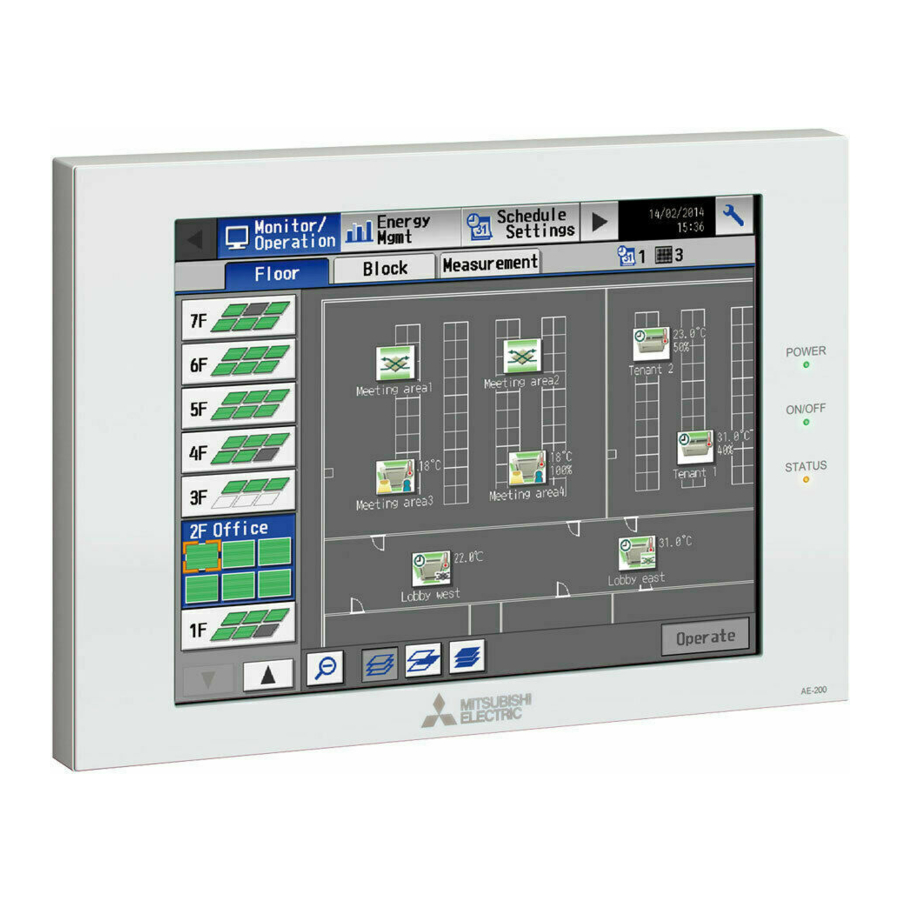
Page 8: Controller Interface
2-5. Controller interface Important ● Before using the controller, remove the protective sheet on the cover to avoid the sheet from sticking to the touch panel and causing malfunctions. ● Use the supplied L-shaped driver to remove or attach the cover. Power LINK/ACT1 USB port... -
Page 9: Number Of Connectable Units
(2 speeds) can be changed. Schedule (Available/Not Avail.) The scheduled operations can be enabled or disabled. Operation Hold (AE-200A/AE-50A only) The Hold function can be enabled or disabled. Prohibition of local remote Some operations or settings from the local remote controllers can be controller operation prohibited. -
Page 10: Maintenance
Function Description ON: One or more units are in operation. ON/OFF/Blink (LED on the OFF: All units are stopped. controller) Blink: One or more units are in error. Operation status of each group The operation status of each group can be displayed. Filter sign The filter sign indicates that the filter is due for cleaning. -
Page 11: Basic Operations
3. Basic operations 3-1. Monitor/Operation This section explains how to monitor and operate the unit groups. 3-1-1. Screen sequence [Floor] display (zoomed-in) [Floor] display (zoomed-out) Touch [ Touch [ Select a group and touch [Operate]. Touch [Floor]. Touch [Block]. Touch [OK] or [Block] display Operation settings screen [Cancel]. -
Page 12: Group Icons
*10 The “Starting up” icon will stay when the unit cannot be recognized after startup. Check for proper connection of the air conditioning unit and proper group settings. *11 The Hold function can be used on the AE-200A/AE-50A, but not on the AE-200E/AE-50E. *12 The “Energy-saving ON” icon takes priority over the “Room temperature display” icon. - Page 13 [3] Air To Water (PWFY) unit group and HWHP (CAHV, CRHV) unit group Error Schedule set Schedule disabled Water temperature Energy-saving ON HOLD ON display (red) *1 The “Energy-saving ON” icon will appear while the Peak Cut control is performed on the Air To Water (PWFY) unit group. This icon will not appear for the HWHP (CAHV, CRHV) unit groups.
-
Page 14: Checking The Operation Conditions
3-1-3. Checking the operation conditions This section explains how to display the operation conditions of units. [1] [Floor] display Touch [Monitor/Operation] in the menu bar, and then touch [Floor]. Note: The unit groups that are under the control of AE-200, AE-50, and EW-50 can be displayed. Weekly schedule number Floor selection Number of units in error... - Page 15 Item Description Floor selection Select a floor you want to monitor. Area selection Select an area of the selected floor you want to monitor. Group name The name of the group will appear. Indoor unit return air temperature will appear. Note: The temperature shown may be different from the actual room temperature.
- Page 16 [2] [Block] display Touch [Monitor/Operation] in the menu bar, and then touch [Block]. Weekly schedule number Block name Number of units in error Block selection Group icons The icon indicates the Number of units whose operation condition of the filter sign is turned on group.
- Page 17 [3] [EM Block] display Touch [Monitor/Operation] in the menu bar, and then touch [Block]. Weekly schedule number EM Block name Number of units in error EM Block selection Group icons The icon indicates the Number of units whose operation condition of the filter sign is turned on group.
- Page 18 [4] [Measurement] display Touch [Monitor/Operation] in the menu bar, and then touch [Measurement]. The measurement data of the temperature sensors, humidity sensors, and metering devices will appear. Note: Measurement settings on the [Measurement] screen under the [Function1] menu are required to display the measurement data on this screen.
- Page 19 [5] [HWHP] display Touch [Monitor/Operation] in the menu bar, and then touch [HWHP]. The operation status of each HWHP (CAHV, CRHV) unit group will appear. Note: The [Controller] setting will appear (only on the AE-200’s LCD) when the [System Exp] setting on the [Unit Info.] screen is set to [Expand].
- Page 20 [6] [AHC] display Touch [Monitor/Operation] in the menu bar, and then touch [AHC]. The status of input and output ports of each Advanced HVAC CONTROLLER (AHC) can be monitored. Note: The [Controller] setting will appear (only on the AE-200’s LCD) when the [System Exp] setting on the [Unit Info.] screen is set to [Expand].
- Page 21 Item Description The number of units that are currently in error will appear. Touching “ ” will bring up the Number of units in error [Malfunction] screen. (See section 3-4-1 “Malfunction List”.) *1 The item will not appear if the number of units is “0.” WT07992X02...
-
Page 22: Selecting The Icons Of The Groups To Be Operated
3-1-4. Selecting the icons of the groups to be operated On the [Floor] or [Block] display under the [Monitor/Operation] menu, select the icon(s) of the group(s) to be operated as explained below, and then touch [Operate] to bring up the operation settings screen. [1] Selecting group icons (1) Selecting a group On the [Floor] or [Block] display, touch the icon(s) of the... - Page 23 (4) Selecting all groups in the selected block On the [Block] display, touch the block(s) you want to Block icon operate. The selected block and group icons will appear with an orange frame. Touch again to deselect. To cancel all group selections, touch the “Deselect-all” button.
-
Page 24: Operation Settings Screen
3-1-5. Operation settings screen On the screen under the [Monitor/Operation] menu, selecting the group icon and touching [Operate] will bring up the operation settings screen for the selected group. The current operation conditions will appear. Change necessary operation settings, and then touch [OK] to save the settings. Touch [Cancel] to return to the previous screen without making any changes. - Page 25 [2] LOSSNAY unit group Refer to section 3-1-6 for details about the setting items. Floor name or block name Group icon Group name ON/OFF Ventilation mode Prohibit Remote Controller Filter Sign Cancel Touch to return to the Schedule previous screen without making any changes.
- Page 26 [4] HWHP (CAHV, CRHV) unit group Refer to section 3-1-6 for details about the setting items. Group icon Group name Set temperature ON/OFF Operation mode Fan Mode Prohibit Remote Controller Cancel Touch to return to the Schedule previous screen without making any changes.
-
Page 27: Operation Setting Items
Operation mode Note: Only the operation modes available for the unit model will appear. Note: The Setback mode can be selected on the AE-200A/AE-50A, but not on the AE-200E/AE-50E. Note: When the operation mode signals from the cooling/heating switchover model of units are mixed (Cool and Heat), the operation mode will not change and the color of the operation mode button will change to a pale orange. - Page 28 Note: [Hold type] can be specified on the [Advanced] screen. Note: The Hold function can be used on the AE-200A/AE-50A, but not on the AE-200E/AE-50E. Touch [Reset] to switch between resetting and not resetting the filter sign after cleaning the filter.
-
Page 29: Energy Management
3-2. Energy Management The energy-control-related status, such as electric energy consumption, operation time, and outdoor temperature, can be displayed in a graph. Also, preset target value of the electric energy consumption can be checked. Note: Energy use status data and ranking data can be output in a CSV format. Note: File names, as well as date formats, delimiter characters, and temperature units (°C, °F) within the files output as CSV will use formats set as initial settings. - Page 30 (1) Touch [Display switching] to set the display items. Note: The [Controller] setting will appear (only on the AE-200’s LCD) when the [System Exp] setting on the [Unit Info.] screen is set to [Expand]. Switch the [Controller] setting between [AE200] and [Exp1] through [Exp4] to display the data for each AE-200, AE-50, and EW-50 individually.
- Page 31 Item Description Specify a date to display the data. Date range Data storage period Display [Day] The last 24 months Date target [Month] The last 24 months [Year] The last 2 years Select [AE] to display the data for AE-200 for comparison, and select [1], [2], [3], or [4] to Controller display the data for each AE-50/EW-50 for comparison.
- Page 32 Item Description Select an item to display its data in the line graph. Note: The selectable items vary, depending on the items selected in the [Display range] and [Display target] fields. Note: For line graph, two items can be selected if the units are the same. Display items for line graph Display range Display target...
- Page 33 (2) Touch [OK] to go back to the previous screen. The display target’s data and the comparison target’s data will appear in a bar graph and a line graph. Note: No graph will appear if no data that meet the specified criteria exist. Item Description Display target...
-
Page 34
Item Description File-name Format contents [yyyy] The year specified in the [Date to display the data] field [mm] The month specified in the [Date to display the data] field [dd] The date specified in the [Date to display the data] field
... -
Page 35
Item Description ■ File format Date Item Format range File Type Month Year yyyy/mm/dd:YYYY/MM/DD Date Month yyyy/mm:YYYY/MM Year yyyy:YYYY Target Display target/Comparison target
“Address” + Address number (Display target) (Bar) + “–” + Display item (Bar), “Address” + Address number (Comparison target) (Bar) + “–”... - Page 36 Item Description ■ File sample (Display range: Block) Date range: Day 2014/08/19:2013/06/01 Block1/Block5 Time,Block1 - Indoor Unit Electric Energy,Block5 - Indoor Unit Electric Energy,Block1 - Outdoor Temp.,Block5 - Outdoor Temp. 00:00,0.61,0.25,23.2,17.8 01:00,0.65,0.51,23.1,17.6 02:00,0.66,0.48,22.1,18.1 03:00,0.66,0.58,23.3,18.2 04:00,0.63,0.47,24.5,17.5 05:00,0.59,0.39,26.8,19.1 06:00,0.52,0.52,28.1,22.1 23:00,0.59,0.23,23.4,17.1 Date range: Month 2014/04:2013/04 Block1/Block5 Day,Block1 - Indoor Unit Electric Energy,Block5 - Indoor Unit Electric Energy,Target electric energy (kWh),Block1 - Outdoor...
-
Page 37: Ranking
3-2-2. Ranking On the Ranking screen, the rankings in electric energy consumption, fan operation time, and Thermo-ON time (Total/ Cool/Heat) of given indoor units can be displayed per block, group, and unit address in descending order in the bar graph. Touch [Energy Mgmt] in the menu bar, and then touch [Ranking]. - Page 38 Item Description Specify a date to display the data in the ranking graph. Date range Data storage period [Day] The last 24 months [Month] The last 24 months Date [Year] The last 5 years Note: Only the data for the period during which the AE-200/AE-50/EW-50 was powered on will appear in the graph.
- Page 39 Item Description Touch [CSV output] to export the displayed ranking data in the CSV format. The CSV file name and file format will vary as shown below, depending on the selected date range. ■ File output destination [Root folder of the USB memory]\[Serial No.]\“OperationalData”\“EnergyManagement”\ ■...
- Page 40 Item Description ■ File sample (Display range: Block) Date range: Day 03/13/2014 All blocks Block name,Indoor Unit Electric Energy,Target electric energy (kWh) Block1,25.19,21.2 Block5,19.58,18.13 Unregistered Blocks,17.01,19.73 Block3,11.2,16.9 Block6,6.19,5.24 Block2,5.98,10.96 Date range: Month 04/2014 All blocks Block name,Indoor Unit Electric Energy,Target electric energy (kWh) CSV output Block1,780.89,657.2 Block5,606.98,562.03...
-
Page 41: Target Value
3-2-3. Target value This section explains how to set the target electric energy consumption values for the entire system for the current year, each month, each day of the week, and each block. The set values will be displayed in the graph on the [Energy Use Status] screen (see section 3-2-1) and the [Ranking] screen (see section 3-2-2). - Page 42 (1) In the [Controller] section, select [AE] to make settings for AE-200, and select [1], [2], [3], or [4] to make settings for each AE-50/EW-50. (2) Touch [Edit] on the left, and set the annual target electric energy, the target usage ratios of the annual electric energy for each month, and the target usage ratios of the electric energy for each day of the week.
- Page 43 3rd page Usage ratio for each day of the week Total of the usage ratios Touch to go to the previous page. Item Description Enter the annual target electric energy consumption value. Note: The value must be between 0 and 4294967 kWh. Annual target electric Note: If the ratio is entered in the “Comparison with previous year”...
- Page 44 (3) Touch [OK] to go back to the previous screen. Note: If the total of the usage ratios for each month and each day of the week are not 100%, the [OK] button cannot be touched. (4) Touch [Edit] on the right, and set the target usage ratios of the electric energy for each block and the [Auto calc.] setting.
-
Page 45: Peak Cut
3-2-4. Peak Cut This section explains how to check the Peakcut control status. Touch [Energy Mgmt] in the menu bar, and then touch [Peakcut]. The average electric power consumption (kW) and the control level will appear in the graph. Note: The [Controller] setting will appear (only on the AE-200’s LCD) when the [System Exp] setting on the [Unit Info.] screen is set to [Expand]. - Page 46 Item Description Touch [CSV output] to export the displayed Peakcut control status data in the CSV format as shown below. ■ File output destination [Root folder of the USB memory]\[Serial No.]\“OperationalData”\“EnergyManagement”\ ■ File name Peakcut_[yyyy]-[mm]-[dd].csv File-name contents Format [yyyy] The year specified in the [Date] field [mm] The month specified in the [Date] field [dd]...
-
Page 47: Schedule
3-3. Schedule Weekly (5 types), annual (5 types), and current day scheduling are available. Schedules can be set for each group, each floor, each block, or all groups. Important ● When one or more AE-50/EW-50 controllers are connected, the schedule settings must be made with the AE-50/EW-50 properly connected to ensure proper settings. - Page 48 Note: When the schedules overlap, schedule with the highest priority will run as shown below. Priority High Today’s schedule Schedules can be set for the current day without modifying the weekly or annual schedules. Annual schedule Different schedules can be set for public holidays or summer vacation.
-
Page 49: Weekly Schedule
3-3-1. Weekly Schedule Touch [Schedule Settings] in the menu bar, and then touch [Weekly1], [Weekly2], [Weekly3], [Weekly4], or [Weekly5]. On the Weekly Schedule settings screen, schedules can be set for each day of the week. Note: When today’s schedule and weekly schedule are set for the same day, today’s schedule settings take precedence over weekly schedule settings. - Page 50 Note: The [HWHP] tab will appear when an HWHP (CAHV, [HWHP] tab CRHV) unit is connected. On the [HWHP] display, touch the icon(s) of the HWHP (CAHV, CRHV) unit group(s) to set the schedule. HWHP (CAHV, CRHV) unit group icon (2) If different equipment types exist together, a screen to select an equipment type will appear.
- Page 51 [3] Selecting a day of the week (1) Touch the day to set the schedule. Day-of-the-week selection The icons of the events that have been set for the Simplified display area selected group will appear in the “Contents of Schedule” section.
- Page 52 Note: The operation items that will appear on the screen vary, depending on the equipment type. Refer to section 3-1-5 “Operation settings screen” for setting details for each unit group. LOSSNAY unit group Air To Water (PWFY) unit group HWHP (CAHV, CRHV) unit group General equipment group Note: When setting a schedule for a block or all groups, all operation modes are available for selection, but the available operation modes depend on the unit model.
- Page 53 [5] Copying a schedule to another day of the week (1) To copy the schedule settings of a day to the schedule Day of the week selection settings for another day of the week, select the day Paste whose schedule settings are to be copied, touch [Copy], Copy select the day to which the copied schedule settings are to be pasted, and touch [Paste].
-
Page 54: Annual Schedule
3-3-2. Annual Schedule Touch [Schedule Settings] in the menu bar, and then touch [Annual]. On the Annual Schedule settings screen, schedules can be set for public holidays or summer vacation. Up to five operation patterns (Pattern A through E) can be set for the 24 months including the current month, and total of 50 days can be allocated to the patterns. - Page 55 [3] Setting the contents of the schedule (1) Touch the row of the schedule to be set in the “Contents of Schedule” section to display the schedule settings screen. Set the start time to apply to the schedule, set the operations to be scheduled, and then touch [OK]. (Refer to section 3-3-1 [4] for details.) [4] Copying a schedule to another pattern Paste...
- Page 56 [6] Saving the schedules (1) To undo the changes made, touch [Cancel] before saving the schedules. After completing the settings, touch [OK] to save the schedules. Cancel [7] Copying a schedule to another group (1) Refer to 3-3-1 [7] for details. WT07992X02...
-
Page 57: Today's Schedule
3-3-3. Today’s Schedule Touch [Schedule Settings] in the menu bar, and then touch [Today]. On the Today’s Schedule settings screen, schedules can be set for the current day without modifying the weekly or annual schedules. Note: Be sure to set the contents of schedule in a way that will not impact on the next day’s operation. For example, if Prohibit setting of remote controller operation is made for any time such as 17: 00, Permit setting needs to be made for any time before the date changes such as 23: 59. -
Page 58: Status List
3-4. Status List 3-4-1. Malfunction List Touch [Status List] in the menu bar, and then touch [Malfunction]. A list of units that are currently malfunctioning will appear. Note: The [Controller] setting will appear (only on the AE-200’s LCD) when the [System Exp] setting on the [Unit Info.] screen is set to [Expand]. - Page 59 Types of units in error and the units that will stop when errors are reset Types of units in error and the units that will stop Units in error Units that will stop AE-200 (AE-50, EW-50) None Outdoor unit All indoor units that are connected to the outdoor unit in error Indoor unit Indoor unit in error and all other indoor units in the same group ME remote controller...
-
Page 60: Filter Sign List
3-4-2. Filter Sign List A list of units whose filter sign is turned on can be displayed. Touch [Status List] in the menu bar, and then touch [Filter Sign]. Note: The [Controller] setting will appear (only on the AE-200’s LCD) when the [System Exp] setting on the [Unit Info.] screen is set to [Expand]. -
Page 61: Malfunction Log
3-5. Malfunction Log 3-5-1. Unit Error/Communication Error Touch [Log] in the menu bar, and then touch [Unit Error] to display unit errors, or touch [Communication Error] to display M-NET communication errors. Note: The [Controller] setting will appear (only on the AE-200’s LCD) when the [System Exp] setting on the [Unit Info.] screen is set to [Expand]. -
Page 62: Error Code List
3-6. Error code list Error codes and their definitions are shown below. If an error occurs, note the error code and consult your dealer. (A) indicates A-control units. 3-6-1. M-NET errors 0092 Version combination error 0093 System configuration change warning 0094 “Charge”... - Page 63 1603 Freezing 1604 Excessive temperature rise protection 1605 Compressor vacuum operation protection 1606 Gas pump abnormality 1607 Composition detection abnormality 1608 Control valve fault delay 1610 Gas leak alarm 1615 Compressor excessive start-stop 1659 Oil equalizing circuit fault delay 2000 Water system abnormality (Pump interlock abnormality) 20*0 Water system abnormality in line *...
- Page 64 4109 Electric system not operate due to OCR51F 4110 Electric system not operate due to high voltage part 4111 Electric system not operate due to bus current 4112 Electric system not operate due to coil overheat 49°C 4113 Electric system not operate due to heater overheat 4114 Electric system not operate due to fan controller abnormality 4115...
-
Page 65: Errors Between Ae-200 And Ae-50 (Ew-50)
6810 Communication error - UR communication error 6811 Communication error - UR communication synchronism not recover 6812 Communication error - UR communication hardware error 6813 Communication error - UR communication status bit detection error 6820 Other communication errors 6821 Other communication errors - Transmission line busy 6822 Other communication errors - No communication ACK 6823... -
Page 66: Practical Operations
4. Practical operations 4-1. Maintenance 4-1-1. Energy data output The operation data of outdoor/indoor units and measurement data can be output to a USB memory device in a CSV format. Touch [Maintenance] in the menu bar, and then touch [Energy data output]. Refer to Table 4-1 “Energy Management Data List”... - Page 67 (3) Touch [Date range] to open the [Select energy management data source] window. Data type Data-acquisition period Cancel (4) Select a data type and specify the data-acquisition period. Touch the [Data type] button to toggle through the following options: [5-minute intervals], [30-minute Data type intervals], [1-day intervals], [1-month intervals], and [1-year intervals].
- Page 68 Item Description ■ File format [Data type: 5-minute intervals] Item Format File Type Data range Start date + “–” + End date “DateTime,Data1(51),...Data1(100),Data2(51),...Data2(100), Data3(51),...Data3(100),OutdoorTemp(51),...OutdoorTemp(100), CoolSetTemp(1),...CoolSetTemp(50),HeatSetTemp(1),...HeatSetTemp(50), RoomTemp(1),...RoomTemp(50),MCP1(0),...MCP1(50), Item *1*2 MCP2(0),...MCP2(50),MCP3(0),...MCP3(50),MCP4(0),...MCP4(50), MCT1(1),...MCT1(50),MCT2(1),...MCT2(50), AHC1(201),...AHC1(250),AHC2(201),...AHC2(250), MCP1,MCP2,MCP3,MCP4 ” Item Unit Data1, Data2, Data3 OutdoorTemp, CoolSetTemp, HeatSetTemp, Measurement ºC, ºF RoomTemp...
- Page 69 Item Description [Data type: 30-minute intervals] Item Format File Type Data range Start date + “–” + End date “DateTime,Data1(51),...Data1(100),Data2(51),...Data2(100), Data3(51),...Data3(100),OutdoorTemp(51),...OutdoorTemp(100), CoolSetTemp(1),...CoolSetTemp(50),HeatSetTemp(1),...HeatSetTemp(50), RoomTemp(1),...RoomTemp(50),FanTime(1),...FanTime(50), CoolTime(1),...CoolTime(50),HeatTime(1),...HeatTime(50), ThermoTime(1),...ThermoTime(50),CoolThermoTime(1),...CoolThermoTime(50), HeatThermoTime(1),...HeatThermoTime(50), Item *1*2 ThermoCount(1),...ThermoCount(50), SaveValue(1),...SaveValue(50),CoolSaveValue(1),...CoolSaveValue(50), HeatSaveValue(1),...HeatSaveValue(50), ApporionedElectricEnergy(1),...ApporionedElectricEnergy(50), MCP1(0),...MCP1(50),MCP2(0),...MCP2(50),MCP3(0),...MCP3(50), MCP4(0),...MCP4(50),MCT1(1),...MCT1(50),MCT2(1),...MCT2(50), AHC1(201),...AHC1(250),AHC2(201),...AHC2(250), MCP1,MCP2,MCP3,MCP4 ” Item Unit ApportionedElectricEnergy ThermoCount, Data1, Data2, Data3 OutdoorTemp, CoolSetTemp, HeatSetTemp, ºC, ºF...
- Page 70 Item Description [Data type: 1-day intervals] Item Format File Type Data range Start date + “–” + End date “Date,Data1(51),...Data1(100),Data3(51),...Data3(100), OutdoorTemp(51),...OutdoorTemp(100),CoolSetTemp(1),...CoolSetTemp(50), HeatSetTemp(1),...HeatSetTemp(50),RoomTemp(1),...RoomTemp(50), FanTime(1),...FanTime(50),CoolTime(1),...CoolTime(50), HeatTime(1),...HeatTime(50),ThermoTime(1),...ThermoTime(50), CoolThermoTime(1),...CoolThermoTime(50), HeatThermoTime(1),...HeatThermoTime(50), Item *1*2 SaveValue(1),...SaveValue(50),CoolSaveValue(1),...CoolSaveValue(50), HeatSaveValue(1),...HeatSaveValue(50), ApporionedElectricEnergy(1),...ApporionedElectricEnergy(50), TargetElectricEnergy(1),...TargetElectricEnergy(50), MCP1(0),...MCP1(50),MCP2(0),...MCP2(50),MCP3(0),...MCP3(50), MCP4(0),...MCP4(50),MCT1(1),...MCT1(50),MCT2(1),...MCT2(50), AHC1(201),...AHC1(250),AHC2(201),...AHC2(250), MCP1,MCP2,MCP3,MCP4 ” Item Unit ApportionedElectricEnergy, TargetElectricEnergy Data1, Data3 OutdoorTemp, CoolSetTemp, HeatSetTemp, ºC, ºF...
- Page 71 Item Description [Data type: 1-month intervals] Item Format File Type Data range Start year and month + “–” + End year and month “Month,Data1(51),...Data1(100),Data3(51),...Data3(100), OutdoorTemp(51),...OutdoorTemp(100),CoolSetTemp(1),...CoolSetTemp(50), HeatSetTemp(1),...HeatSetTemp(50),RoomTemp(1),...RoomTemp(50), FanTime(1),...FanTime(50),CoolTime(1),...CoolTime(50), HeatTime(1),...HeatTime(50),ThermoTime(1),...ThermoTime(50), CoolThermoTime(1),...CoolThermoTime(50), HeatThermoTime(1),...HeatThermoTime(50), Item *1*2 SaveValue(1),...SaveValue(50),CoolSaveValue(1),...CoolSaveValue(50), HeatSaveValue(1),...HeatSaveValue(50), ApporionedElectricEnergy(1),...ApporionedElectricEnergy(50). TargetElectricEnergy(1),...TargetElectricEnergy(50), MCP1(0),...MCP1(50),MCP2(0),...MCP2(50),MCP3(0),...MCP3(50), MCP4(0),...MCP4(50),MCT1(1),...MCT1(50),MCT2(1),...MCT2(50), AHC1(201),...AHC1(250),AHC2(201),...AHC2(250), MCP1,MCP2,MCP3,MCP4 ”...
- Page 72 Item Description [Data type: 1-year intervals] Item Format File Type Date range Start year + “–” + End year “Year,Data1(51),...Data1(100),Data3(51),...Data3(100), FanTime(1),...FanTime(50),CoolTime(1),...CoolTime(50), HeatTime(1),...HeatTime(50),ThermoTime(1),...ThermoTime(50), CoolThermoTime(1),...CoolThermoTime(50), HeatThermoTime(1),...HeatThermoTime(50),SaveValue(1),...SaveValue(50), CoolSaveValue(1),...CoolSaveValue(50), *1*2 Item HeatSaveValue(1),...HeatSaveValue(50), ApporionedElectricEnergy(1),...ApporionedElectricEnergy(50) TargetElectricEnergy(1),...TargetElectricEnergy(50), MCP1(0),...MCP1(50),MCP2(0),...MCP2(50),MCP3(0),...MCP3(50), MCP4(0),...MCP4(50), MCP1,MCP2,MCP3,MCP4 ” Item Unit ApportionedElectricEnergy, TargetElectricEnergy Data1, Data3 Measurement unit FanTime, CoolTime, HeatTime, ThermoTime,...
- Page 73 Energy Management Data List Table 4-1 below summarizes the energy-control-related items that can be output in a CSV format, their measurement units, and their data ranges for each data type. Table 4-2 below summarizes how many months/years worth of data each CSV file can contain. Table 4-1 Data items Data type (intervals) Measurement...
-
Page 74: Maintenance
5. Maintenance 5-1. Backing up settings data The settings data can be exported to a USB memory as a backup. Touch [Maintenance] in the menu bar, and then touch [Backup]. Note: Use the USB memory device that meets the requirements described in section 4-1-1 “Energy data output”. Note: IP address settings will not be backed up. -
Page 75: Importing Settings Data
5-2. Importing settings data The exported data can be imported back to the AE-200/AE-50/EW-50 to restore the previous settings after the controller replacement. Touch [Maintenance] in the menu bar, and then touch [Import]. All settings Read from USB Memory Touch to import the settings data. -
Page 76: Csv Output
5-3. CSV output The operation data, such as charge parameters and metering device data, can be output in a CSV format. Touch [Maintenance] in the menu bar, and then touch [CSV output]. Note: A separate license may be required to use the CSV output function. Only valid buttons can be selected on the screen. Note: Refer to section 4-1-1 “Energy data output”... - Page 77 Item Description ■ File name (without connection to an AE-50/EW-50 controller) “ChargeParameter”_[yyyy]-[mm]-[dd]“A”[Indoor unit address]-[Time period (1–5)].csv Example: ChargeParameter_2015-03-01A01-1.csv (with connection to one or more AE-50/EW-50 controllers) “ChargeParameter”_[yyyy]-[mm]-[dd]“A”[AE-50/EW-50 No. (1–4) ]-[Indoor unit address]-[Time period (1–5)].csv Example: ChargeParameter_2015-03-01A1-01-1.csv *1 AE-50/EW-50 No. will not be shown for the AE-200 data. Note: Time periods 1 through 5 can only be set from TG-2000A or Initial Setting Tool.
- Page 78 Item Description ■ File name (without connection to an AE-50/EW-50 controller) “ChargeParameter30m”_[yyyy]-[mm]-[dd]“A”[Indoor unit address]-[Time period (1–5)].csv Example: ChargeParameter30m_2015-03-01A01-1.csv (with connection to one or more AE-50/EW-50 controllers) “ChargeParameter30m”_[yyyy]-[mm]-[dd]“A”[AE-50/EW-50 No. (1–4) ]-[Indoor unit address]-[Time period (1–5)].csv Example: ChargeParameter30m_2015-03-01A1-01-1.csv *1 AE-50/EW-50 No. will not be shown for the AE-200 data. Note: Time periods 1 through 5 can only be set from TG-2000A or Initial Setting Tool.
- Page 79 Item Description ■ File name (PI controller (PAC-YG60MCA) - without connection to an AE-50/EW-50 controller) “ChargeParameter”_[yyyy]-[mm]-[dd]“MCPA”[PI controller address]-[Time period (1–5)].csv Example: ChargeParameter_2015-03-01MCPA50-1.csv (Built-in Pulse Input (PI) - without connection to an AE-50/EW-50 controller) “ChargeParameter”_[yyyy]-[mm]-[dd]“MCP”-[Time period (1–5)].csv Example: ChargeParameter_2015-03-01MCP-1.csv (PI controller (PAC-YG60MCA) - with connection to one or more AE-50/EW-50 controllers) “ChargeParameter”_[yyyy]-[mm]-[dd]“MCPA”[AE-50/EW-50 No.
-
Page 80
Item Description ■ File format Item Format File Type Data range Start date + “–” + End date
“MCP” + M-NET address + “–” + Time period (1–5) “MCP”... - Page 81 Item Description ■ File name (PI controller (PAC-YG60MCA) - without connection to an AE-50/EW-50 controller) “ChargeParameter30m”_[yyyy]-[mm]-[dd]“MCPA”[PI controller address]-[Time period (1–5)].csv Example: ChargeParameter30m_2015-03-01MCPA50-1.csv (Built-in Pulse Input (PI) - without connection to an AE-50/EW-50 controller) “ChargeParameter30m”_[yyyy]-[mm]-[dd]“MCP”-[Time period (1–5)].csv Example: ChargeParameter30m_2015-03-01MCP-1.csv (PI controller (PAC-YG60MCA) - with connection to one or more AE-50/EW-50 controllers) “ChargeParameter30m”_[yyyy]-[mm]-[dd]“MCPA”[AE-50/EW-50 No.
- Page 82 Item Description ■ File format Item Format File Type Data range Start date + “–” + End date (PI controller (PAC-YG60MCA) - without connection to an AE-50/EW-50 controller) “MCP” + PI controller address + “–” + Time period (1–5) (Built-in Pulse Input (PI) - without connection to an AE-50/EW-50 controller) “MCP”...
-
Page 83: Touch Panel Calibration
5-4. Touch Panel Calibration Touch [Maintenance] in the menu bar, and then touch [Touch Panel Calibration]. Start calibration (1) Touch [Start calibration]. (2) Touch the white squares in the order they appear, White dot starting from the top left corner. The white squares will change to gray when touched. -
Page 84: Cleaning The Touch Panel
5-6. Cleaning the touch panel (1) Touch [ ] to display the login window. (2) On the Login window, touch the “Touch-panel-cleaning” button. Touch-panel-cleaning (3) Clean the touch panel with a soft dry cloth, a well-wrung cloth that has been soaked in water with mild detergent, or a cloth dampened with ethanol. -
Page 85: Specifications
6. Specifications Item Specifications Power supply Rated input 100–240 VAC ± 10%; 0.3–0.2 A 50/60 Hz Single-phase No specifications M-NET power feeding coefficient * Only an MN converter can be connected. Operating temperature 0°C – +40°C (+32°F – +104°F) range Temperature Ambient Storage temperature... -
Page 86: Appendix: Added Functions
Appendix: Added functions The table below summarizes the newly added functions. Version Menu item Added function Reference Energy management data of the units Energy Energy Use Section 3-2-1 “Energy Ver. 7.2 connected to different AE-200/AE-50/EW-50 Management Status Use Status” controllers can be compared. Units can be monitored and operated in energy Section 3-1-3 “Checking Blocks... - Page 87 This equipment has been tested and found to comply with the limits for a Class B digital device, pursuant to Part 15 of the FCC Rules. These limits are designed to provide reasonable protection against harmful interference in a residential installation.
- Page 88 This product is designed and intended for use in the residential, commercial and light-industrial environment. The product at hand is based on the following EU regulations: • Low Voltage Directive 2006/95/EC • Electromagnetic Compatibility Directive 2004/108/EC • Restriction of Hazardous Substances 2011/65/EU Please be sure to put the contact address/telephone number on this manual before handing it to the customer.