Table of Contents
HP 2U UPS
User Guide
Abstract
This document is for the person who installs and maintains HP UPS products. HP assumes you are qualified
in the installation of electrical equipment and trained in recognizing hazards in products with hazardous
energy levels.
Part Number: 792519-001
November 17, 2014
Edition: 1
Table of Contents

Related Manuals for HP R/T2200 G4 NA/JP


Summary of Contents for HP R/T2200 G4 NA/JP
-
Page 1: User Guide
HP 2U UPS User Guide Abstract This document is for the person who installs and maintains HP UPS products. HP assumes you are qualified in the installation of electrical equipment and trained in recognizing hazards in products with hazardous energy levels. -
Page 2: Important Safety Instructions
0 to 40°C/32 to 104°F, free of conductive contaminant. For HP R/T3000 HV NA/JP and HP R/T3000 G4 INTL UPS models: • FCC/EN55022 Class B IEC62040-2 C1 For HP R/T2200 G4 NA/JP and HP R/T3000 G4 LV NA/JP UPS models: • FCC/EN55022 Class A, IEC62040-2 C2 Certification Standards •... -
Page 3: Personal Safety
Battery Module provided with the UPS to maintain an identical level of performance and safety. For questions, contact your HP representative. Important: Replace the battery module with the same type battery module, available from HP. Page 3... -
Page 4: Table Of Contents
5.4 Spares ....................................28 6. Technical Specifications ....................29 6.1 HP R/T2200 G4 NA/JP UPS and HP R/T3000 G4 LV NA/JP UPS ..............29 6.2 HP R/T3000 G4 HV NA/JP UPS and HP R/T3000 G4 INTL UPS ..............30 7. Support and other resources ..................31... -
Page 5: Overview
Follow all local regulations for the disposal of packing materials. End of life HP processes products at the end of their service lives in compliance with local regulations. HP works with companies in charge of collecting and eliminating our products at the end of their service lives. Product The product is made up of recyclable materials. -
Page 6: Weights And Dimensions
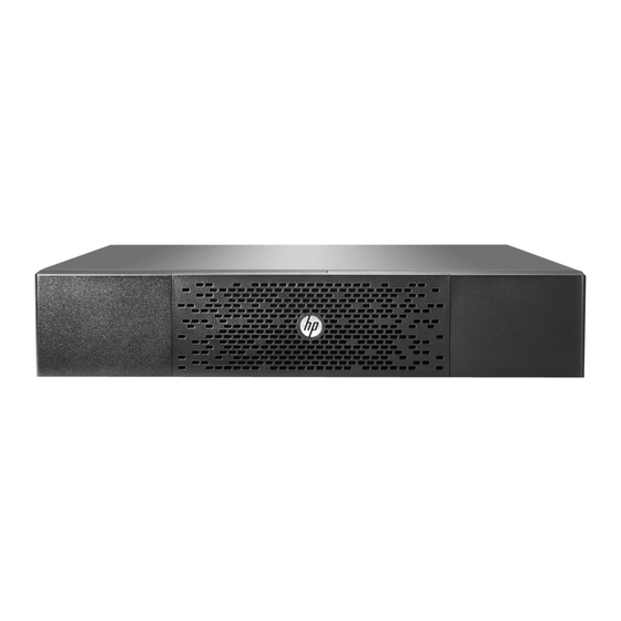
Description Weights Dimensions (mm/inch) (kg/lb) D x W x H HP R/T2200 G4 NA/JP UPS 30.5 kg/67.2 lb 523 x 442 x 86 mm/20.6 x 17.4 x 3.4 in HP R/T3000 G4 LV NA/JP UPS 39.9 kg/88.0 645 x 442 x 86 mm/25.4 x 17.4 x 3.4 in. -
Page 7: Rear Panels
(Although the LED remains on the rear panel, this feature is disabled for low voltage models.) Ground connection HP R/T3000 G4 HV NA/JP UPS and HP R/T3000 G4 USB communication port RS-232 communication port INTL UPS Connector for automatic recognition of an... -
Page 8: User Interface
2. User Interface 2.1 Control panel The UPS has a five-button graphical control panel. Power On On battery Alarm Indicator (green) Indicator (yellow) Indicator (red) Normal mode 100% 100% 2.7kW 17min 3kVA 1ERM E ciency: ~98% Escape Down Enter On/Off button The following table shows the indicator status and description: Indicator... -
Page 9: Lcd Window
2. User Interface 2.2 LCD window The LCD window provides useful information about the UPS, load status, events, measurements, and settings. As the default, or after five minutes of inactivity, the LCD displays the screen saver. The backlight LCD automatically dims after 10 minutes of inactivity. Press any button to restore the screen. Operation Status Normal mode 100%... -
Page 10: Display Functions
2. User Interface 2.3 Display functions Press the button to activate the menu options. Use the buttons to scroll through the menu structure. Press button to select an option. Press the button to cancel or return to the previous menu. Menu map for Display Functions. - Page 11 2. User Interface Continued Available settings Description Default settings Load segments - Auto [Disable] [0s] [1 s] [2 s]…[65354 s] Group 1: Disable shutdown delay During a power outage, this setting Group 2: Disable enables the UPS to turn off power to equipment connected to Group 1 and/or Group 2 outlets, or disables the action.
-
Page 12: Installation
3. Installation 3.1 Unpacking and contents check HP R/T2200 G4 NA/JP UPS and HP R/T3000 G4 LV NA/JPN UPS (14) HP R/T2200 G4 NA/JP and HP R/T3000 G4 LV NA/JPN (20) Mounting brackets, rails, and hardware (15) Bezel parts (21) Tower stands... - Page 13 3. Installation HP R/T3000 G4 HV NA/JPN UPS and HP R/T3000 G4 INTL UPS (30) HP R/T3000 G4 HV NA/JPN and HP R/T3000 G4 INTL (36) Documentation (31) Connection cable to AC power source (38) Mounting brackets, rails, and hardware (L6-20P for NA/JP model.
-
Page 14: Battery Module Connection
Installing the new battery module Perform the removal instructions in reverse order. ● To ensure safety and high performance, only use batteries supplied by HP. ● Take care to firmly press together the two parts of the connector during remounting. -
Page 15: Tower Installation
3. Installation 3.3 Tower installation M3 screws M3 screws 3.4 Rack installation Warning: To reduce the risk of personal injury or damage to the equipment, be sure that: • The leveling feet are extended to the floor. • The full weight of the rack rests on the leveling feet. •... - Page 16 3. Installation Installing the mounting rails Front of rack Prepare the rail. 1. Loosen the wing nuts or hex nuts. 2. Extend the brackets to the appropriate length. Insert screws through the rail and each mounting bracket. M6 screws Rear of rack Install cage nuts or clip nuts behind the mouting holes where you will attach the mounting brackets.
- Page 17 3. Installation Rear of rack (cont.) Tighten the wing nuts or hex nuts. Installing the UPS in the rack Before installing the UPS, review and adhere to all safety information (see page 2 and page 3). The mounting rails must be installed before installing the UPS. Warning: A risk of personal injury or damage to the equipment exists.
- Page 18 3. Installation Shipping the UPS in the rack Before shipping the UPS in the rack, you will need to add a rear rail stabilizing bracket and install a protective cover over the bezel. Install the rear stabilizing rail Install the rear stabilizing rail. 1.
-
Page 19: Communication Ports
USB RS-232 communication port on the UPS. The UPS can now communicate with HP power management software. Characteristics of the optocoupler RS-232 communications port • Pins 1, 3, 4, 5, 6, 10: not used • Pin 2: common (user) •... -
Page 20: Ups Connection
3. Installation 3.6 UPS connection HP R/T2200 G4 NA/JP UPS Check that the specifications on the rear UPS name plate correspond to the AC power source and the true electrical consumption of the total load. 1. Connect the UPS input plug to the AC power source. -
Page 21: Ground Connection
3. Installation HP R/T3000 G4 HV NA/JP and R/T3000 G4 INTL UPS Check that the indications on the name plate located on the back of the UPS correspond to the AC-power source and the true electrical consumption of the total load. -
Page 22: Erm And Ups Installation
There are two ERM models. They can be installed with UPSs in both rack and tower installations. Up to four ERMs can be installed with each UPS. HP R/T2200 G4 ERM HP R/T3000 G4 ERM Mounting ERM on the rails Follow steps 1 through 4 for mounting the ERM on the rails. - Page 23 3. Installation ERM and UPS connection Rack configuration 1 x ERM 2 x ERM Tower configuration 2 x ERM 1 x ERM M3 screws Note: The connected power cord between UPS and ERM must be provided by original manufacturer only. Page 23 792519-001 Edition 1...
-
Page 24: Operation
4. Operation 4.1 Start-up and normal operation To start the UPS: 1. Verify that the UPS power cord is plugged in. 2. The UPS LCD window display illuminates and the logo displays. 3. Press the button on the UPS control panel for at least two seconds. 4. -
Page 25: Return Of Ac Input Power
4. Operation Low-battery warning • indicator illuminates. • The audio alarm beeps every 3 seconds. The remaining battery power is low. Shut down all applications on the connected equipment because automatic UPS shutdown is imminent. End of battery backup time •... -
Page 26: Maintenance
The UPS does not protect the equipment. Note: Record the alarm message and the UPS Serial Number, then contact your service representa- tive. 5.2 Updating the UPS firmware To update the UPS firmware, see the HP website (http://www.hp.com/go/rackandpower). Page 26 792519-001 Edition 1... -
Page 27: Battery Module Replacement
Minimize the amount of time the UPS uses battery power by matching the UPS configuration with the utility vol- tage (see "6.1 HP R/T2200 G4 NA/JP UPS and HP R/T3000 G4 LV NA/JP UPS" on page 29 and "6.2 HP R/T3000 G4 HV NA/JP UPS and HP R/T3000 G4 INTL UPS"... -
Page 28: Spares
Installing the new battery module Perform the removal instructions in reverse order. • To ensure safety and high performance, use only batteries supplied by HP. • Take care to firmly press together the two parts of the connector during remounting. -
Page 29: Technical Specifications
6. Technical Specifications 6.1 HP R/T2200 G4 NA/JP UPS and HP R/T3000 G4 LV NA/JP UPS Transformer Filter Charger Inverter Battery HP R/T2200 G4 NA/JP UPS HP R/T3000 G4 LV NA/JP UPS Output Power @ 120V NA: 1920 VA NA: 2880 VA... -
Page 30: Hp R/T3000 G4 Hv Na/Jp Ups And Hp R/T3000 G4 Intl Ups
6. Technical Specifications 6.2 HP R/T3000 G4 HV NA/JP UPS and HP R/T3000 G4 INTL UPS Transformer Filter Charger Inverter Battery HP R/T3000 G4 HV NA/JP UPS HP R/T3000 G4 INTL UPS Output Power @ 200V 2490V 2490V 2241W 2241W... -
Page 31: Support And Other Resources
• Download and have available an Active Health System log for 7 days before the failure was detected. For more information, see the HP iLO 4 User Guide or HP Intelligent Provisioning User Guide on the HP website (http://www. hp.com/go/ilo/docs).