beautypg.com
Manuals
Brands
YASKAWA Manuals
Controller
FSDrive-MV1000 Series
YASKAWA FSDrive-MV1000 Series Manuals
Manuals and User Guides for YASKAWA FSDrive-MV1000 Series. We have
5
YASKAWA FSDrive-MV1000 Series manuals available for free PDF download: Instructions For Use Manual, Parameter Manual, Instructions Manual
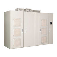
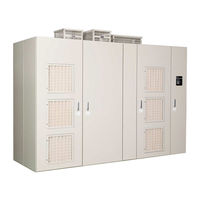
YASKAWA FSDrive-MV1000 Series Instructions For Use Manual (260 pages)
Super Energy-Saving Medium-Voltage AC Drive
Brand:
YASKAWA
| Category:
Controller
| Size: 21.77 MB
Table of Contents
Table of Contents
3
Preface and General Safety
9
Preface
10
Applicable Documentation
10
Symbols
10
Terms and Abbreviations
10
Trademarks
10
General Safety
11
Supplemental Safety Information
11
Safety Messages
12
Drive Label Warning Example
14
Mechanical Interlock
17
Notes on Using Drives
18
Selection
18
Installation
18
Settings
19
General Handling
19
Notes on Motor Operation
21
Existing Standard Motors
21
Warranty Information
22
Warranty Period
22
Scope of Warranty
22
Restrictions
22
1 Receiving
23
Section Safety
24
General Description
25
Fsdrive-MV1000 Model Selection
25
Control Mode Selection
28
Model Number and Nameplate Check
29
Nameplate
29
Drive Model Number Definition
30
Component Names and Configurations
31
External Appearance and Internal Layout
31
Digital Operator, Communications Connector, and Internal Layout for Control Panel
35
Transformer Panel
36
Power Cell Panel
36
Control Panel
36
2 Mechanical Installation
39
Section Safety
40
Mechanical Installation
42
Installation Environment
42
Installation Space
43
Drive Transportation
44
Side-By-Side Installation
57
Installing Cooling Exhaust Covers
58
Installing a Drive on a Floor
58
Dimensions
66
Storing Drives
71
Short Term Storage of Drives
71
Long Term Storage of Drives
71
3 Electrical Installation
73
Section Safety
74
Standard Connection Diagram
77
Class: 2 Kv
77
Class: 3 Kv
78
Class: 4 Kv
79
Class: 6 Kv
80
Class: 11 Kv
81
Terminals
82
Cable Routing
85
Main Circuit Cable Routing
85
Cable Routing Precautions
88
Main Circuit Wiring
90
Main Circuit Terminals (Common to All Capacities)
90
Wire Gauges and Tightening Torques
91
Main Circuit Terminal and Motor Wiring
98
Control Circuit Wiring
99
Control Circuit Terminals
99
Control Circuit Terminal Layout and Specifications
101
Wiring the Control Circuit Terminal
102
Connecting to a PC
103
External Interlock
104
Drive Ready
104
Wiring Check
105
Checks
105
4 Start-Up Programming & Operation
107
Section Safety
108
Using the Digital Operator
109
Keys and Displays
109
LCD Display
110
ALARM (ALM) LED Displays
111
LO/RE LED and RUN LED Indications
111
Menu Structure for Digital Operator
112
The Drive and Programming Modes
113
Navigating the Drive and Programming Modes
114
Changing Parameter Settings or Values
117
Verifying Parameter Changes: Verify Menu
117
Switching between LOCAL and REMOTE
118
Setup Group Parameters
119
Start-Up Flowcharts
120
Flowchart A: Basic Start-Up and Motor Tuning
120
Subchart A-1: Parallel Operation of Multiple Motors by V/F Control
121
Subchart A-2: High Performance Operation Using OLV or CLV
122
Powering up the Drive
123
Powering up the Drive and Status Display
123
Auto-Tuning
124
Types of Auto-Tuning
124
Before Auto-Tuning the Drive
125
Auto-Tuning Interruption and Fault Codes
125
Auto-Tuning Operation Example
126
Parameter Settings During Auto-Tuning for Induction Motors
127
No-Load Operation Test Run
130
Test Run with Load Connected
132
Test Run with the Load Connected
132
Checking and Saving Parameter Default Values
133
Saving User Default Values: O2-03
133
Parameter Access Level: A1-01
133
Password Settings: A1-04, A1-05
134
Copy Function
134
5 Troubleshooting
137
Section Safety
138
Motor Performance Fine-Tuning
140
Fine-Tuning V/F Control
140
Fine-Tuning Open Loop Vector Control
140
Fine-Tuning Closed Loop Vector Control
142
Parameters to Minimize Motor Hunting and Oscillation
142
Types of Faults, Alarms, and Errors
143
Fault, Alarm and Error Displays
144
Fault Detection
148
Fault Displays, Causes, and Possible Solutions
148
Alarm Detection
162
Alarm Codes, Causes, and Possible Solutions
162
Operator Programming Error
170
Ope Codes, Causes, and Possible Solutions
170
Auto-Tuning Fault Detection
174
Auto-Tuning Codes, Causes, and Possible Solutions
174
LED Indicators on the Controller and Cell Control Board
177
LED Indicators on the Controller
177
LED Indications on the Cell Control Board
178
Copy Function Related Displays
179
Tasks, Errors, and Troubleshooting
179
Diagnosing and Resetting Faults
181
Fault Occurs Simultaneously with Power Loss
181
If the Drive Still Has Power after a Fault Occurs
181
Viewing Fault Trace Data after Fault
181
Fault Reset Methods
182
Troubleshooting Without Fault Display
183
Common Problems
183
Cannot Change Parameter Settings
183
Motor Does Not Rotate Properly after Pressing RUN Button or after Entering External Run Command
184
Motor Is too Hot
185
Drive Does Not Allow Selection of Rotational Auto-Tuning
185
Motor Stalls During Acceleration or with Large Loads or Acceleration Time Is too Long
186
Drive Frequency Reference Differs from the Controller Frequency Reference Command
186
Excessive Motor Oscillation and Erratic Rotation
187
Electrical Interference from Drive or Output Lines When the Drive Is Powered on
187
Connected Machinery Vibrates When Motor Rotates
187
PID Output Fault
187
Insufficient Starting Torque
188
Motor Rotates after the Drive Output Is Shut off (Motor Rotates During DC Injection Braking)
188
Output Frequency Is Not as High as Frequency Reference
188
Motor Does Not Restart after Power Loss
188
6 Periodic Inspection & Maintenance
189
Section Safety
190
Inspection
192
Recommended Daily Inspection
192
Recommended Periodic Inspection
193
Periodic Maintenance
196
Part Replacement Guidelines
196
Performance Life Monitors/Maintenance Monitors
196
Replacing the Battery
198
Battery Replacement Procedure
198
Replacing the Cooling Fan
200
Models and Number of Cooling Fans Used
200
Cooling Fan Replacement Procedure
203
Replacing Power Cells
204
Power Cell Replacement Procedure
204
Spare Parts
207
Storing Spare Parts
208
7 Options
211
Section Safety
212
Options
213
Built-In Type
213
Panel Housed Type
214
Separate Installation Type
214
Specifications
215
Model-Specific Specifications
216
Class: 2 Kv
216
Class: 3 Kv
216
Class: 4 Kv
217
Class: 6 Kv
217
Class: 11 Kv
217
Drive Specifications
218
Standards Compliance
219
European Standards
220
European Standards Compliance
220
Memobus/Modbus Communications
223
Memobus/Modbus Configuration
224
Communication Specifications
225
Connecting to a Network
226
Network Cable Connection
226
Wiring Diagram for Multiple Connection
226
Network Termination
227
Memobus/Modbus Setup Parameters
228
Memobus/Modbus Serial Communication
228
Drive Operations by Memobus/Modbus
231
Observing the Drive Operation
231
Controlling the Drive
231
Communications Timing
232
Command Messages from Master to Drive
232
Response Messages from Drive to Master
232
Message Format
233
Message Content
233
Slave Address
233
Function Code
233
Data
233
Error Check
233
Message Examples
235
Reading Drive Memobus/Modbus Register Contents
235
Loopback Test
235
Writing to Multiple Registers
236
Memobus/Modbus Data Table
237
Command Data
237
Monitor Data
239
Broadcast Messages
249
Fault Trace Contents
249
Alarm Register Contents
251
Enter Command
252
Enter Command Types
252
H5-11 and the Enter Command
252
Communication Errors
253
Memobus/Modbus Error Codes
253
Slave Not Responding
253
Index
254
Revision History
259
YASKAWA FSDrive-MV1000 Series Instructions Manual (190 pages)
Super Energy-Saving Medium-Voltage AC Drive
Brand:
YASKAWA
| Category:
Controller
| Size: 14.52 MB
Table of Contents
Table of Contents
3
Preface and General Safety
7
Before Using the Product
8
Applicable Documentation
8
Symbols
8
Terms and Abbreviations
8
Trademarks
8
General Safety
9
Supplemental Safety Information
9
Safety Messages
10
Drive Label Warning
12
Mechanical Interlock
14
Notes on Using Drives
15
Selection
15
Installation
15
Settings
16
General Handling
16
Notes on Motor Operation
18
Application to Existing Standard Motors
18
Warranty Information
19
Warranty Period
19
Scope of Warranty
19
Restrictions
19
1 Receiving
21
Section Safety
22
General Description
23
Fsdrive-MV1000 Model Selection
23
Control Mode Selection
25
Model Number and Nameplate Check
26
Nameplate
26
Descriptions of Drive Models
27
Component Names and Configuration
28
Transformer Panel
30
Power Cell Panel
30
Control Panel
30
2 Mechanical Installation
33
Section Safety
34
Mechanical Installation
35
Installation Environment
35
Checking the Installation Space
36
Transporting
37
Side-By-Side Installation
41
Installing Cooling Exhaust Covers
43
Installing a Drive on a Floor
43
Dimensions
47
Storing Drives
50
Short Term Storage of Drives
50
Long Term Storage of Drives
50
3 Electrical Installation
53
Safety Messages
54
Standard Connection Diagram
57
Class: 2 Kv
57
Class: 4 Kv
58
Terminals
59
Routing Cables
60
Check before Routing Cables
60
Caution When Routing Cables
62
Main Circuit Wiring
63
Main Circuit Terminals (Common to All Capacities)
63
Wire Gauges and Tightening Torques
64
Main Circuit Terminal and Motor Wiring
68
Control Circuit Wiring
69
Control Circuit Terminals
69
Control Circuit Terminal Layout and Specifications
71
Wiring the Control Circuit Terminal
72
Connecting to a PC
73
External Interlock
74
Drive Ready
74
Wiring Check
75
Checks
75
4 Start-Up Programming & Operation
77
Section Safety
78
Using the Digital Operator
79
Keys and Displays
79
LCD Display
80
ALARM (ALM) LED Displays
81
LO/RE LED and RUN LED Indications
81
Menu Structure for Digital Operator
82
The Drive and Programming Modes
83
Navigating the Drive and Programming Modes
84
Changing Parameter Settings or Values
87
Verifying Parameter Changes: Verify Menu
87
Switching between LOCAL and REMOTE
88
Setup Group Parameters
89
Start-Up Flowcharts
90
Flowchart A: Basic Start-Up and Motor Tuning
90
Subchart A-1: Simple Motor Setup Using V/F Control, or Serial Operation
91
Of Multiple Motors
91
Subchart A-2: High Performance Operation Using OLV or CLV
92
Power up and Checking the Operation Display Status
93
Power up the Drive and Checking the Operation Display Status
93
Auto-Tuning
94
Auto-Tuning Type
94
Before Auto-Tuning the Drive
95
Auto-Tuning Interruption and Fault Codes
95
Auto-Tuning Operation Example
96
Parameter Settings During Auto-Tuning for Induction Motors
97
No-Load Operation Test Run
100
Test Run with Load Connected
102
Test Run with the Load Connected
102
Verifying Parameter Settings and Backing up Changes
103
User Parameter Default Value (O2-03)
103
Access Level of Parameter (A1-01)
103
Password (A1-04, A1-05)
104
Copy Function
104
5 Troubleshooting
107
Section Safety
108
Motor Performance Fine-Tuning
110
Fine-Tuning V/F Control
110
Fine-Tuning Open Loop Vector Control
110
Fine-Tuning Closed Loop Vector Control
111
Parameters to Minimize Motor Hunting and Oscillation
112
Types of Faults, Alarms, and Errors
113
Fault, Alarm and Error Displays
114
Fault Detection
118
Fault Displays, Causes, and Possible Solutions
118
Alarm Detection
130
Alarm Codes, Causes, and Possible Solutions
130
Operator Programming Error
139
Ope Codes, Causes, and Possible Solutions
139
Auto-Tuning Fault Detection
143
Auto-Tuning Codes, Causes, and Possible Solutions
143
LED Indicators on the Controller and CCB (Cell Control Board)
146
LED Indicators on the Controller
146
LED Indications on the Cell Control Board
147
Copy Function Related Displays
148
Tasks, Errors, and Troubleshooting
148
Diagnosing and Resetting Faults
150
Fault Occurs Simultaneously with Power Loss
150
If the Drive Still Has Power after a Fault Occurs
150
Viewing Fault Trace Data after Fault
150
Fault Reset Methods
151
Troubleshooting Without Fault Display
152
List of Key Phenomena
152
Cannot Change Parameter Settings
152
Motor Does Not Rotate Properly after Pressing RUN Button or after Entering External Run Command
153
Motor Is too Hot
154
Drive Does Not Allow Selection of Rotational Auto-Tuning
155
Motor Stalls During Acceleration or with Large Loads/Acceleration Time Is too Long
155
Drive Frequency Reference Differs from the Controller Frequency
155
Reference Command
155
Excessive Motor Oscillation and Erratic Rotation
156
Noise from Drive or Output Lines When the Drive Is Powered on
156
Connected Machinery Vibrates When Motor Rotates
156
PID Output Fault
156
Insufficient Starting Torque
157
Motor Rotates after the Drive Output Is Shut off (Motor Rotates During DC Injection Braking)
157
Output Frequency Is Not as High as Frequency Reference
157
Motor Does Not Restart after Power Loss
157
6 Periodic Inspection & Maintenance
159
Section Safety
160
Periodic Inspection
162
Daily Inspection
162
Periodic Inspection
163
Maintenance
166
Part Replacement Guidelines
166
Replacing the Battery
167
Battery Replacement Procedure
167
Replacing the Cooling Fan
169
Models and Number of Cooling Fans Used
169
Cooling Fan Replacement Procedure
171
Replacing Power Cells
172
Power Cell Replacement Procedure
172
Spare Parts
174
Storing Spare Parts
176
7 Options
177
Section Safety
178
Options
179
Built-In Type
179
Panel Housed Type
180
Separate Installation Type
180
Specifications
181
Model-Specific Specifications
182
Class: 2 Kv
182
Class: 4 Kv
182
Drive Specifications
183
Index
184
Revision History
189
YASKAWA FSDrive-MV1000 Series Parameter Manual (230 pages)
Super Energy-Saving Medium-Voltage AC Drive, 2.4 kV Class, 3 kV Class, 4.16 kV Class, 6 kV Class, 11 kV Class
Brand:
YASKAWA
| Category:
Controller
| Size: 16.73 MB
Table of Contents
Table of Contents
3
Preface and General Safety
7
Before Using the Product
8
Applicable Documentation
8
Symbols
8
Terms and Abbreviations
8
Trademarks
8
General Safety
9
Supplemental Safety Information
9
Safety Messages
10
Notes on Using Drives
12
Selection
12
Installation
12
Settings
13
General Handling
13
Notes on Motor Operation
15
Application to Existing Standard Motors
15
Warranty Information
16
Warranty Period
16
Scope of Warranty
16
Restrictions
16
1 Parameter List
17
Understanding the Parameter Table
18
Control Modes, Symbols, and Terms
18
Parameter Groups
19
Parameter Table
20
A: Initialization Parameters
20
B: Application
22
C: Tuning
28
D: References
32
E: Motor Parameters
36
F: Option Parameters
40
H: Terminal Functions
46
L: Protection Function
59
N: Special Adjustment
65
O: Operator Related Settings
66
T: Motor Tuning
68
U: Monitors
70
Control Mode Dependent Parameter Default Values
79
A1-02 (Motor 1 Control Mode) Dependent Parameters
79
E3-01 (Motor 2 Control Mode) Dependent Parameters
81
Defaults by Drive Model Selection (O2-04)
82
2 Parameter Details
87
A: Initialization
88
A1: Initialization
88
A2: User Parameters
93
A3: Trace Data
94
B: Application
95
B1: Operation Mode Selection
95
B2: DC Injection Braking
102
B3: Speed Search
103
B4: Delay Timers
109
B5: PID Control
110
B6: Dwell Function
121
B7: Droop Control (CLV)
122
C: Tuning
123
C1: Acceleration and Deceleration Times
123
C2: S-Curve Characteristics
125
C3: Slip Compensation
126
C4: Torque Compensation
129
C5: Automatic Speed Regulator (ASR)
131
D: Reference Settings
135
D1: Frequency Reference
135
D2: Frequency Upper/Lower Limits
137
D3: Jump Frequency
138
D4: Frequency Reference Hold and Up/Down 2 Function
139
D5: Torque Control
144
D6: Field Weakening and Field Forcing
149
D7: Offset Frequency
150
E: Motor Parameters
151
E1: 1V/F Pattern for Motor 1
151
E2: Motor 1 Parameters
152
E3: V/F Pattern for Motor 2
155
E4: Motor 2 Parameters
156
F: Option Settings
158
F1: PG Speed Control Card Settings
158
F2: Analog Input Card Settings
160
F3: Contact Input Card Settings
161
F4: Analog Monitor Card Settings
161
F5: Contact Output Card Settings
163
F6: Communication Option Card Settings
164
PROFIBUS-DP Parameters
165
Devicenet Parameters
165
H: Terminal Functions
166
H1: Contact Inputs
166
H2: Contact Outputs
176
H3: Analog Inputs
187
H4: Analog Outputs
193
H5: Memobus/Modbus Serial Communication
195
L: Protection Functions
196
L1: Motor Protection
196
L2: Momentary Power Loss Ride-Thru
198
L3: Stall Prevention
200
L4: Speed Detection
204
L5: Fault Restart
205
L6: Torque Detection
207
L7: Torque Limit
210
L8: Drive Protection
212
N: Special Adjustments
218
N1: Hunting Prevention
218
N2: Speed Feedback Detection Control (AFR) Tuning
219
N9: I/O Voltage Detection
219
O: Operator Related Settings
221
O1: Digital Operator Display Selection
221
O2: Digital Operator Keypad Functions
222
O3: Copy Function
225
O4: Maintenance Monitor Settings
225
T: Motor Tuning
227
U: Monitor Parameters
228
U1: Operation Status Monitors
228
U2: Fault Trace
228
U3: Fault History
228
U4: Maintenance Monitors
228
U5: PID Monitors
228
U6: Control Monitors
229
U9: Power Cell Monitor
229
Revision History
230
YASKAWA FSDrive-MV1000 Series Parameter Manual (241 pages)
Super Energy-Saving Medium-Voltage AC Drive, 2.4 kV Class, 3 kV Class, 4.16 kV Class, 6 kV Class, 11 kV Class
Brand:
YASKAWA
| Category:
Controller
| Size: 18.7 MB
Table of Contents
Table of Contents
3
Preface and General Safety
7
Preface
8
Applicable Documentation
8
Symbols
8
Terms and Abbreviations
8
Trademarks
8
General Safety
9
Supplemental Safety Information
9
Safety Messages
10
Drive Label Warning Example
12
Mechanical Interlock
15
Notes on Using Drives
16
Selection
16
Installation
16
Settings
17
General Handling
17
Notes on Motor Operation
19
Existing Standard Motors
19
Warranty Information
20
Warranty Period
20
Scope of Warranty
20
Restrictions
20
Parameter List
21
Understanding the Parameter Table
22
Control Modes, Symbols, and Terms
22
Parameter Groups
23
Parameter Table
24
A: Initialization Parameters
24
B: Application
26
C: Tuning
32
F: Options
42
L1: Motor Protection
63
L2: Momentary Power Loss Ride-Thru/Main Power Supply
64
L3: Stall Prevention
65
L4: Speed Detection
65
L5: Fault Restart
66
L6: Torque Detection
66
L7: Torque Limit
68
L8: Drive Protection
68
N: Special Adjustments
70
N1: Hunting Prevention
70
N7: Synchronous Transfer with a Commercial Power Supply
71
N9: I/O Voltage Detection
72
O: Operator Related Settings
72
O1: Digital Operator Display Selection
72
O3: Copy Function
74
T: Motor Tuning
75
YASKAWA FSDrive-MV1000 Series Instructions Manual (70 pages)
Super Energy-Saving Medium-Voltage AC Drive. Class: 2 kV, 3 kV, 4 kV, 6 kV, and 11 kV
Brand:
YASKAWA
| Category:
Controller
| Size: 3.64 MB
Table of Contents
Table of Contents
3
Preface and General Safety
7
Before Using the Product
8
Applicable Documentation
8
Symbols
8
Terms and Abbreviations
8
Trademarks
8
General Safety
9
Supplemental Safety Information
9
Safety Messages
10
Drive Label Warning
12
Mechanical Interlock
16
Notes on Using Drives
17
Selection
17
Installation
17
Settings
18
General Handling
18
Notes on Motor Operation
20
Application to Existing Standard Motors
20
Warranty Information
21
Warranty Period
21
Scope of Warranty
21
Restrictions
21
1 Receiving
23
Section Safety
24
General Description
25
Fsdrive-MV1000 Model Selection
25
Control Mode Selection
28
Model Number and Nameplate Check
29
Nameplate
29
Descriptions of Drive Models
31
Component Names and Configuration
32
Transformer Panel
36
Power Cell Panel
36
Control Panel
36
2 Mechanical Installation
39
Section Safety
40
Mechanical Installation
41
Installation Environment
41
Checking the Installation Space
42
Transporting
43
Side-By-Side Installation
56
Main Circuit Wiring
58
Installing Cooling Exhaust Covers
59
Installing a Drive on a Floor
59
Dimensions
65
Storing Drives
70
Short Term Storage of Drives
70
Long Term Storage of Drives
70
Spare Parts
70
Related Products
YASKAWA FS100L
YASKAWA FSDrive-MV1S
YASKAWA FSP Series
YASKAWA MOTOMAN FS100
Yaskawa F Series
YASKAWA VIPA SLIO FM 050
YASKAWA FP605
YASKAWA FM 050
YASKAWA 050-1BA00
YASKAWA 1000 Series
YASKAWA Categories
Controller
DC Drives
Servo Drives
Robotics
Control Unit
More YASKAWA Manuals