beautypg.com
Manuals
Brands
HP Manuals
Inverter
8672a
HP 8672a Manuals
Manuals and User Guides for HP 8672a. We have
3
HP 8672a manuals available for free PDF download: Service Manual, Manual, Operating And Service Manual
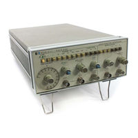
HP 8672a Service Manual (600 pages)
synthesized signal generator
Brand:
HP
| Category:
Portable Generator
| Size: 28.71 MB
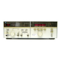
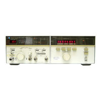
HP 8672a Manual (318 pages)
SYNTHESIZED SIGNAL GENERATOR
Brand:
HP
| Category:
Portable Generator
| Size: 19.95 MB
Table of Contents
Table of Contents
8
Schematic Diagram
9
Adjustment and Test Point Locations
9
Component, Adjustment, and Point Locations
9
Diagrams
9
Diagram
9
Detector Assembly
9
Component, Adjustment
9
Locations
9
Phase
9
ILLUSTRATIONS (Cont'D)
9
Specifications
14
Recommended Test Equipment
19
USA Standard Code for Information Interchange (ASCII)
27
Front Panel Features
29
Rear Panel Features
30
Local Operator's Checks
34
Local Operating Instructions
36
Output Level
38
Modulation
39
ALC Arguments
43
(With RF ON)
45
Programming Quick Reference Guide
46
Modulation Index
65
Factory Selected Components
100
Related Adjustments
101
20/30 Mhz
113
A2A5 20/30 Mhz Divider Assembly
122
Replaceable Parts
138
Reference Phase
174
P/0 A2A11 Timing and
214
And Test Point Locations
215
P/0 Timing and
216
Phase Detector
224
A3A1A5
226
HP-IB Diagnostic Program
231
Schematic Diagram
234
Front Panel
237
Control Block
248
A2A4
259
Vco
259
HP-IB Address
259
M/N
259
A3A1A1 Reference Phase
259
Mhz VCXO
259
Phase Detector Assembly
259
A3A1A4A2
259
Block Diagrams
260
Overall Troubleshooting
261
M/N Output Assembly
271
HP 8672a Operating And Service Manual (69 pages)
Function generator
Brand:
HP
| Category:
Inverter
| Size: 3.95 MB
Table of Contents
Warranty
3
Safety Information
3
Safety Symbols
3
Table of Contents
6
List of Tables
7
List of Illustrations
7
Safety Summary
8
Sweep Output. Output Level
10
Burst. Symmetry. Specifications
10
Instrument and Manual Identification
10
Specifications
11
General Information Table
11
Installation
12
Power Requirements. Grounding Requirements
12
Instrument Mounting. Repackaging for Shipment
12
Power Plugs Diagram
12
Operating Instructions
13
Controls and Indicators
13
General Operating Information
13
Generator Outputs
13
Front Panel Diagram
14
Rear Panel Diagram
15
Input Constraints
15
Mudulation Generator Input/Output
15
Output Characteristics
15
Sine Wave Output. Square Wave Output. Triangle Output
16
Ramp. Pulse. Gate or Burst. am
16
Phase Control of Burst Diagram
16
Percent Modulation Diagram
16
Basic Operating Procedures
17
Instrument Turn-On. Fuse Replacement
17
FM. SWP. External Control
17
Frequency. Amplitude
17
Main Generator Operation. Burst
18
Vco
18
Modulation Generator Operation
18
AM Operation Diagram
18
FM Operation Diagram
19
Sweep Operation Diagram
19
Burst Operation Diagram
20
Theory of Operation
21
Basic Block Diagram Description
21
Functional Block Diagram Description
22
Main Generator Section
22
Calibrated Symmetry Diagram
22
Variable Symmetry Diagram
22
Output Section
23
Modulation Generator
23
Level Shifter Diagram
23
Signal Generator Diagram
24
U403 Burst Amplifier Array Diagram
25
Burst Time Relation Waveforms Diagram
25
Required Test Equipment
27
Maintenance
28
Performance Tests
28
Dial Accuracy Test Table
28
Aberration Test
29
Triangle Linearity Test
29
Rise Time Test
29
Triangle Linearity (Positive Slope) Table
30
Triangle Linearity (Negative Slope) Table
30
Sweep Ramp Linearity Test
31
Linearity Table
32
Sine Wave Distortion Test
32
Output Impedance Test
33
Attenuator Accuracy Test
33
Sine Wave Level Flatness Test
33
Amplitude Flatness Diagram
33
Sync Output Impedance and Amplitude Test
34
Sync Output Rise and Fall Time Test. DC Offset Test
34
Internal Modulation Source Output Level Test
34
Internal Modulation Source Spectral Purity Test
34
Variable Symmetry Test
35
Carrier Envelope Distortion Test
35
External Amplitude Modulation Sensivitity Test
35
FM Distortion Test
35
Carrier 3 Db Bandwidth Test (Amplitude Modulation)
36
Frequency Deviation Test
36
FM Distortion Diagram
36
External Frequency Control Input Requirements, VCO Linearity Tests
37
VCO Linearity Graph
37
Adjustment Procedures
38
Power Supply Adjustment
38
Frequency Adjustment
38
Distorstion Adjustment
39
Rise Time and Aberration Adjustment
39
Modulation Symmetry Adjustment
39
Modulation Sinewave Distortion Adjustment
39
Factory Selected Values
40
Factory Selected Components Table
40
Carrier Balance Adjustment
40
Adjustment Locator Diagram
41
Performance Test Card
42
Replaceable Parts
44
Ordering Information
44
Chassis Mounted and Miscellaneous Parts. Non-Listed Parts
44
Standard Abbreviations Table
44
Code List of Manufacturers
45
Replaceable Parts Table
46
Chassis Mounted Components Picture
55
3312A Jack Connections
56
General Schematic Notes
56
Circuit Diagrams
57
Reference Designators
57
Troubleshooting
57
Functional Block Diagram
57
3312A Settings Table
58
Tuning Amplifier Integrator and Ranges Switches Diagram
60
3312A Settings
64
Backdating
66
Related Products
HP HP 8673D
HP 8671B
HP HP 8642A/B
HP 8614A
HP 8642A
HP 8642B
HP 8656A
HP 8655A
HP 8690B
HP 8663A
HP Categories
Desktop
Laptop
Server
Monitor
Switch
More HP Manuals