beautypg.com
Manuals
Brands
Honeywell Manuals
Security System
VISTA-128FBPN
Honeywell VISTA-128FBPN Manuals
Manuals and User Guides for Honeywell VISTA-128FBPN. We have
1
Honeywell VISTA-128FBPN manual available for free PDF download: Installation And Setup Manual
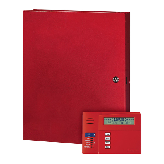
Honeywell VISTA-128FBPN Installation And Setup Manual (128 pages)
Commercial Fire and Burglary Partitioned Security System with Scheduling
Brand:
Honeywell
| Category:
Security System
| Size: 0.96 MB
Table of Contents
Table of Contents
3
Conventions Used in this Manual
7
General Requirements
9
Programming Field Settings for UL864 Compliance
9
Section 1
15
About the VISTA-128FBPN
15
Features
15
Guidelines for Wiring a System
17
Figure 1-1: Isolating Fire Devices from Burglary Devices
18
Section 2
19
Theory of Partitioning
19
Setting-Up a Partitioned System
19
Common Lobby Logic
19
Master Keypad Setup and Operation
21
Section 3
23
Mounting the Control Cabinet
23
Installing the Cabinet Lock
23
Mercantile Premises Listing Guidelines
23
Figure 3-1: Installing the Lock
23
Mercantile Safe and Vault Listing Guidelines
24
Commercial Fire Guidelines
24
Figure 3-2: Cabinet Attack Resistance Considerations
24
Figure 3-3: Commercial Fire Installation Considerations
24
Installing the Control's Circuit Board
25
Installing the Keypads
25
Figure 3-4: Mounting the PC Board
25
Installing External Sounders
26
Figure 3-5: Keypad Connections to Control Panel
26
Figure 3-6. ECP Isolator Wiring
26
Figure 3-7: Intentionally Left Blank
26
Auxiliary Relay Connections
30
Figure 3-8: Wiring Auxiliary Relay for Alarm Activation
30
Figure 3-9: Wiring Auxiliary Relay for Smoke Detector Reset
30
Telephone Line Connections
31
Main Dialer Connections
31
Wiring Burglary and Panic Devices to Zones 1-8
32
Figure 3-10: 2-Wire Smoke Detector on Zone 1 (for Zone 2 Use Terminals 17 and 18)
33
Figure 3-11: 4-Wire Smoke Detectors
34
Figure 3-13: Wiring a Normally Closed Sensor Loop for Tamper Supervision
35
Figure 3-12. Wiring Latching Glassbreaks to Zone 8
35
Installing V-Plex Devices
36
Figure 3-14: Wiring a Normally Open Sensor Loop for Tamper Supervision
36
Figure 3-15: Polling Loop Connections to the Control Panel
38
Figure 3-16: Polling Loop Connections Using One 4297 Extender Module
38
Wireless Zone Expansion
39
Figure 3-17: Polling Loop Connections Using Multiple Extender Modules
39
Figure 3-18: Installing the 5881ENHC with Tamper Protection
41
Installing Output Devices
43
Figure 3-20: 4204 Relay Module
43
Installing a Remote Keyswitch
44
Figure 3-21: 4204CF Relay Module
44
Installing a Remote Keypad Sounder (for Commercial Burglary Use Only)
45
Figure 3-22: Remote Keyswitch Wiring
45
Figure 3-23: Remote Keypad Sounder Wiring
45
Communicators Connected to the ECP
46
Event Log Connections
47
Figure 3-24: Wiring Communicator to Keypad Terminals
47
Connecting the Transformer
48
Earth Ground Connections
48
Determining the Control's Power Supply Load
49
Determining the Size of the Standby Battery
51
Figure 3-25: Connecting the Backup Batteries
52
Section 4
53
Program Modes
53
Entering and Exiting Programming Mode
53
Data Field Programming Mode
53
#93 Menu Mode Programming
54
Zone Number Designations
56
Zone Response Type Definitions
58
Zone Input Type Definitions
60
Programming for Communicator
61
Section 5
63
About Data Field Programming
63
Programming Data Fields
63
Ignore Expansion Zone Tamper
65
Intelligent Test Report
65
Test Report Interval
65
Event Display Lock
76
Section 6
79
Scheduling Options
79
Time Window Definitions
80
Open/Close Schedules Definitions
81
Scheduling Menu Mode
82
Time Windows
83
Daily Open/Close Schedules
84
Holiday Schedules
84
Time-Driven Events
85
Limitation of Access Schedules
89
Temporary Schedules
90
User Scheduling Menu Mode
92
Section 7
93
General Information
93
Unattended Download (for Burglary Use Only)
93
Getting On-Line with a Control Panel
95
Scheduled Download (for Burglary Use Only)
95
Direct-Wire Downloading
96
Telco Handoff
96
Figure 7-1: Direct-Wire Downloading Connections
96
Section 8
97
General Information
97
Setting the Time and Date
97
Section 9
99
General Information
99
User Codes and Levels of Authority
99
Multiple Partition Access
100
Adding a Master, Manager, or Operator Code
101
Changing a Master, Manager, or Operator Code
102
Deleting a Master, Manager, or Operator Code
102
Exiting the User Edit Mode
102
Section 10
103
Battery Test
103
Dialer Test
103
Fire Drill Test (Code + [#] + 69)
103
One-Man Fire Walk-Test (Code + [#] + 68)
103
Burglary Walk-Test
104
Armed Burglary System Test
105
Testing Wireless Transmitters
105
Trouble Conditions
106
To the Installer
107
Appendix A
109
Appendix A
109
UL Installation Requirements
109
UL864/NFPA Local Fire
109
UL864/NFPA Central Station and Remote Station Fire
109
Commercial Burglary Requirements
109
UL609 Local Mercantile Premises/Local Mercantile Safe & Vault
110
UL365 Police Station Connected Burglar Alarm
110
UL1610 Central Station Burglary Alarm
110
Summary of System Commands
113
Specifications
115
Appendix D
117
Appendix C
117
Appendix B
117
Appendix C
117
Appendix D
117
Table of Contact ID Event Codes
117
Event Log Alpha Descriptors
118
Related Products
Honeywell VISTA-128FBP
Honeywell Ademco VISTA-128FB
Honeywell VISTA-128SIA
Honeywell VISTA-128BP
Honeywell VISTA-128BPTSIA
Honeywell VISTA-128BPT
Honeywell VISTA-128FBPT
Honeywell VISTA-128BPEN
Honeywell ADEMCO VISTA-12A
Honeywell ADEMCO Vista-12C
Honeywell Categories
Thermostat
Controller
Control Unit
Security Camera
Accessories
More Honeywell Manuals