beautypg.com
Manuals
Brands
GE Manuals
Medical Equipment
Voluson 730ProV
GE Voluson 730ProV Manuals
Manuals and User Guides for GE Voluson 730ProV. We have
2
GE Voluson 730ProV manuals available for free PDF download: Service Manual
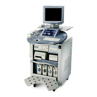
GE Voluson 730ProV Service Manual (333 pages)
Brand:
GE
| Category:
Medical Equipment
| Size: 14.33 MB
Table of Contents
Important Precautions
3
Damage in Transportation
6
Legal Notes
7
Proprietary to Ge Medical Systems
7
List of Effected Pages
9
Table of Contents
11
CHAPTER 1 Introduction
27
Introduction
27
Overview
27
Purpose of Chapter 1
27
Purpose of Service Manual
27
Typical Users of the Basic Service Manual
28
Models Covered by this Manual
28
Purpose of Operator Manual(S)
28
Important Conventions
29
Conventions Used in Book
29
Standard Hazard Icons
30
Standard Icons Indicating a Special Procedure be Used
30
Product Icons
31
Safety Considerations
33
Human Safety
33
Mechanical Safety
33
Introduction
33
Electrical Safety
34
Probes
34
Safe Practices
34
Labels Locations
35
Dangerous Procedure Warnings
35
Lockout/Tagout Requirements (for USA Only)
36
Returning/Shipping Probes and Repair Parts
36
Electromagnetic Compatibility (EMC)
36
What Is EMC
36
Electrostatic Discharge (ESD) Prevention
37
Customer Assistance
37
Compliance
37
Contact Information
37
System Manufacturer
38
CHAPTER 2 Pre-Installation
39
Overview
39
Purpose of Chapter 2
39
General Console Requirements
40
Console Environmental Requirements
40
Electrical Requirements
40
Cooling
40
Inrush Current
40
Lighting
40
Voluson® 730Pro / 730Prov Power Requirements
40
Site Circuit Breaker
41
Site Power Outlets
41
Unit Power Plug
41
EMI Prevention/Abatement
42
EMI Limitations
42
Scan Probe Environmental Requirements
43
Time and Manpower Requirements
43
Facility Needs
44
Purchaser Responsibilities
44
Required Features
44
Desirable Features
45
Minimal Floor Plan Suggestion
46
DICOM Option Pre-Installation Requirements
47
Purpose of the DICOM Network Function
47
CHAPTER 3 Installation
49
Installation Reminders
49
Average Installation Time
49
Overview
49
The Purpose of Chapter 3
49
Installation Warnings
50
Acclimation Time
50
Brake Pedal Operation
50
Operator I/O Panel Position
50
Safety Reminders
51
Environmental Labels
51
Envelope at Front Panel of the Crate
52
Receiving and Unpacking the Equipment
52
Unpacking Procedure
52
Preparing for Installation
54
Physical Inspection
54
System Voltage Settings
54
EMI Protection
54
Verify Customer Order
54
Connection of Auxiliary Devices
55
Connection of Peripherals
55
Figure 3-6 Remove Rear Cover Plate
56
Figure 3-7 GND Ground-Cable
56
Foot Switch Connection
57
Foot Switch Connection Scheme
57
Monitor Connection
57
ECG Connection Scheme
58
ECG-Preamplifier Connection
58
Global Modem Connection
59
Global Modem Connection Scheme
59
S-VHS Video Recorder Connection
60
Mitsubishi - Video Recorder Connection Scheme
60
Mitsubishi HS-MD3000
60
DIP Switches
61
Sony SVO-9500MD
61
Video Recorder Connection Scheme
61
B/W Video Printer Connection
62
B/W Video Printer Connection Scheme
62
Line Printer Connection
63
Line Printer Connection Scheme
63
Digital Color Printer Connection
64
Digital Color Printer Connection Scheme
64
Bluetooth Printer Connection
65
Bluetooth Printer Connection Scheme
65
External USB-Devices
66
Connection
66
Unplug or Eject Hardware
66
Safe to Remove Hardware
67
Stop a Hardware Device
67
Completing the Installation
68
Power on / Boot up
68
Back-End Processor Boot up
68
Scanner Power on
68
Back-End Processor Power down
69
Power Off/ Shutdown
69
Scanner Shutdown
69
Transducer Connection
70
Printer Installation
71
Found New Hardware Wizard
72
Installing Line Printer HP 990Cxi or HP 995C
72
Confirm Correct Path and Finish the Installation
73
Search for Network Path on Hard Disk
73
Install the UP-D21MD / UP-D23MD Printer Software/Driver
74
Installing Digital Color Printer Sony UP-D21MD or UP-D23MD
74
Search for Network Path
75
Printer Installation Manually
76
Service Tools Window
76
System Setup Service Page
76
Add Printer and Printer Installation/Properties
77
Add Printer Wizard
77
Select Printer Port
78
Complete Manual Printer Installation
80
Adjustment of Printer Settings
81
Select the Desired Printer
81
HP 990Cxi / HP 995C- Printer Settings
82
HP Printer - Settings
82
UP-D21MD / UP-D23MD - Printer Settings
83
HP 5600 Series / Olivetti Job Jet 210 - Printer Settings
85
Peripherals Page
86
Printer Remote Control Selection
86
Electrical Specifications
87
System Configuration
87
System Specifications
87
Left Trackball Key (Left Mouse Button)
88
System Setup
88
Trackball (Mouse Position)
88
Upper Trackball Key (Right Mouse Button)
88
How to Change Language (And/Or EUM Language)
89
How to Enter Date and Time
89
How to Enter Hospital Name
89
How to Change Video Norm
90
Approved Peripherals
91
On-Board Optional Peripherals
91
External I/O Connection Panel (GES)
92
External I/O Connector Descriptions
92
External I/O Panel Connectors
92
External I/O Pin Outs
93
Modem, RJ-11 Modular 6 Pin
93
Network Connector, RJ45 Modular 8 Pin
93
VGA out Connector, Sub-D 15 Pin
93
COMP VIDEO out Connector
94
Footswitch Connector
94
Video Specification
94
Video Specifications VGA Connector
94
Electrical Specifications on VGA Connector
95
Video Specifications for Composite, Video Connector
95
Software/Option Configuration
96
Connectivity Installation Worksheet
97
Internet Protocol (TCP/IP)
98
Network Configuration
98
Network IP Address Configuration
98
Map Network Drive
99
Map Network Drive Window
99
Paperwork
100
Product Locator Installation
100
Product Locator Installation Card
100
User Manual(S)
100
Functional Checks
101
Required Equipment
101
General Procedure
102
ON/OFF Standby Switch
103
Power off / Shutdown
103
Scanner Shutdown
103
Control Panel
104
Control Panel Tour
104
System Features
104
Menu Control
105
Menu Control Area- 2D Main Menu
105
Monitor Display
106
Monitor Display Features
106
Monitor Display Tour
106
2D Main and 2D Sub
108
2D Mode Checks
108
2D Mode Functions
108
M Main and M Sub
111
M Mode Checks
111
MCFM Main and MCFM Sub Menu
112
MCFM Mode Check
112
PW Main and PW Sub
113
Spectral Doppler Mode (PW, CW) Functions
113
Spectral Doppler Mode Checks
113
CFM Main and CFM Sub Menu
115
Color Doppler Mode (CFM, PD, TD) Functions
115
Color Doppler Mode Checks
115
Pre-Volume Mode Functions
117
Pre-Volume Mode Menus
117
Volume Mode Checks
117
D/4D Main - Sectional Planes and Image Rendering
118
Functions after the 3D Acquisition
118
3D/4D Sub Menu
120
Sub Menu
120
Activating 2D Auto Cine
121
Activating Cine
121
Cine-Split Function (Multiple Format)
121
Using Cine
121
Distance and Tissue Depth Measurements (2D and M Mode)
122
General Remarks to Perform Generic Measurements
122
Generic Measurements
122
Circumference/Area Measurements
123
Multiplane Measurements
123
Volume Measurements
123
Auto Trace
124
Heart Rate
124
Manual Trace
124
Measurements in Spectral Doppler Mode
124
Calculations
125
Worksheet (Report) Pages
125
Activating the Probe
126
Connecting a Probe
126
Deactivating the Probe
126
Probe/Connectors Usage
126
Image Management (Sonoview)
127
Sonoview
127
Using the MOD (Magneto-Optical Drive)
128
Formatting Media
129
MO Disk Formatter Messages
129
MO Disk Formatter Window
129
Adjusting the Write Speed of the DVD/CD Recorder
130
Erase DVD/CD Window
130
Erasing Disk
130
Settings of the DVD/CD Recorder
130
Backup and Restore Database, Preset Configurations and Images
131
System Setup - Backup Page
131
Save User Settings Only (Application Settings)
132
User Settings Only - Save Window
132
Load Backup Data
133
Load User Settings Only (Application Settings)
133
User Settings Only - Load Window
133
Load Only Parts of the Backup
134
Full Backup Save
135
Save Full Backup (Presets, Configurations & Application Settings)
135
Directory Structure of Full Backup Data
136
Load Full Backup (Presets, Configurations & Application Settings)
137
Full Backup Load
138
Select Data to be Restored
138
Delete Full Backup (Presets, Configurations & Application Settings)
139
Full Backup Delete
139
Archiving Images
140
Backup Windows
140
Sonoview Screen
140
Measurement Setup Checks
141
Software Configuration (System Setup) Checks
141
Software Configuration Checks
141
ECG Check out
142
ECG Preamplifier Check
142
Peripheral Checks
142
Brakes and Direction Locks
143
Locking Lever under Control Console
143
Mechanical Function Checks
143
Rotation of the Control Console
143
Maintenance Report
144
Site Log
144
Site Log - System (Service Database)
144
Components and Functions (Theory)
147
General Information
148
Voluson 730Pro / 730Prov Major Components
148
Major System Components
149
B-Mode or 2D-Mode
152
Coded Harmonic Imaging (HI)
152
M-Mode
152
MCFM Mode (M Mode + Color Flow Mode)
152
Color Doppler Mode
153
Color Flow Mode
153
Power Doppler
153
Tissue Doppler
153
3D Data Collection and Reconstruction
154
3D Image Presentation
154
3D Imaging
154
3D Rendering
154
B-Mode
157
Cpr
157
Crs
157
Dataflow Control Description
157
Special B Mode Techniques
158
D-Mode (Pulsed Wave- and Continuous Wave Doppler)
159
D-Mode Autotrace
159
CFM-Mode (Color Flow Mode)
160
Extern-Video-Mode (Display Video from Video-Recorder)
160
Description of Software Options
161
Real Time 4D
161
Software Options
161
Sonoview Write Mode (Store Image to Sonoview)
161
Dicom
162
Real Time 4D Biopsy
162
SRI - Speckle Reduction Imaging
162
VOCAL II - Virtual Organ Computer-Aided Analysis
162
STIC (Spatio-Temporal Image Correlation)
163
TUI - Tomographic Ultrasound Imaging
163
VCI - Volume Contrast Imaging
163
CW - Continuous Wave Doppler
164
Description of Hardware Options
164
Hardware Options
164
Scan/Freeze Foot Switch
164
Leds
165
Leds on Modem
165
Location in the Unit
165
Front
166
Main Board Chassis GEF Module
166
Mechanic of GEF Module
166
Rear with Internal I/O (Audio Video)
166
Frontend Processor
167
Frontend Processor - Block Diagram
167
CPR - Beamformer-Motherboard
168
CPU - Probe Connector Board
168
Frontend - Board Descriptions
168
Block Diagram CPD
169
CPD-Beamformer-Sub-Board
169
CPK - Motherboard of GEF-Module
170
CPZ - Cover Board
170
CRW - CW-Doppler Board (Optional)
170
CPP- Power Supply Secondary Board + Motor Power Stage
171
CRS - Signal Processor Board
171
Block Diagram CPP
172
Backend Processor
173
Backend Processor - Block Diagram
173
Block Diagram CKV
174
DMA Controller
174
Video I/O
174
Backend - Board Descriptions
175
CPE - Back Panel I/O-Card
175
CPM - PC-Motherboard Card
175
GES - External IO Board
177
Internal I/O
177
Connectors on the Main Module of the GEF
178
Connectors on PC-Part of the GEF
179
Console Module
180
DC/DC Converter
180
Top Console
180
Menu Key
185
Monitor
185
External I/O
186
External I/O Connector Description
186
DVD/CD+(R)W Drive
187
ECG-Preamplifier (MAN6 - Optional)
187
Magneto-Optical Drive (Optional)
187
Peripherals
187
CPN6 - Primary Power Module
188
Major Functions of CPN6
188
Power Distribution
188
Fuses Inside CPN6
189
Fuses on Rear Panel (CPN6)
189
CPN80 - Primary Power Module
190
Major Functions of CPN80
190
Mechanical Concept and Overview
190
Disk Drive Module (GEM)
191
Fuses Inside CPN80
191
Fuses on CPE-Board for Disk Drive Module (GEM)
191
Fuses on Rear Panel (CPN80)
191
Mechanical Descriptions
192
Physical Dimensions
192
Top Console Positioning
193
Assembly Drawing GW & GEU & Monitor
194
Air Flow Control
195
Air Flow Distribution
195
Air Flow Distribution Overview
195
Access / Security
196
Service Platform
196
Ilinq Interactive Platform
197
Service Page
198
Auto Tester File
199
Video Norm
199
Delete All Patients
200
Export System Data
200
Service Viewer
200
Monitor Test
201
Eum
202
Nls
202
Printer
202
Uis
202
Service Adjustments
203
Monitor Adjustment
204
Monitor Adjustment Buttons
204
Monitor Calibration
204
Color Temp - Calibration
205
Degauss
205
Monitor Test - Main Menu
205
Color Temperature
206
Contrast and Brightness
206
Convergence
206
Geometry
206
Control Console, Transport Lock
207
Trackball - Securing Ring
208
Trackball Adjustment
208
Trackball with Fixing Ring
208
Diagnostics/Troubleshooting
209
Collect Vital System Information
210
Needed Data - in Case of System Crash or Errors
211
AUX Supply
212
Check Points Voltages
212
ECG Connector
212
How to Check Power
212
Capturing a Screen
213
Export Log’s and System Data
213
Screen Captures and Logs
213
Export System Data (by Pressing the ALT + D Key)
214
Dump-File
215
System Has Encountered a Problem
215
How to Use the Auto Tester Program
216
Booting Without Using the Ultrasound Hardware
219
Minimum Configuration to Boot/Scan
219
Cable- Minimum Configuration
220
Minimum Configuration to Scan
220
System Does Not Power on / Boot up
221
Troubleshooting Trees and Instructions
221
Noise Disturbs the Image
222
Trackball
223
System Does Not Power off / Shutdown
224
Monitor Troubleshooting
225
Unable to Record to VCR
226
VCR - Troubleshooting
226
Printer Troubleshooting
227
DVD/CD+(R)W Troubleshooting (DVD/CD Drive)
229
MOD Troubleshooting
229
To Backup Exams to DVD/CD+(R)W Resp. MO-Disk
229
GE Remote Service Connection
230
Network Troubleshooting
230
No Connection to the Network at All
230
Error Messages
231
Replacement Procedures
241
Ultrasound Application Software (UIS) Installation Procedure
242
Option Page
243
Version Check
243
DICOM Configuration
244
Software - Installation Procedure (Via Service Page)
245
Full Backup (Presets, Configurations & Appl. Settings)
248
User Settings Only (Application Settings) Loading Procedure
248
Manpower
249
Service Platform (SSW) Upgrade Procedure
249
Electronic User Manual (EUM) Upgrade Procedure
251
EUM - Upgrade Procedure
252
Software and Functional Checks after the Upgrade
254
System Setup - System Info Page
254
Operation for Activating Options
255
Option Page in the System Setup
255
Replacement or Activation of Options
255
Transfer of Patient Database and Images from System-To-System
257
Backup All Exams of the “Old” System
258
Transfer of Patient Database and Images Via Sonoview
258
Restore All Exams (of the “Old” System) to the “New” System
259
Identical Exam Already Exists
260
Remove Cover of the Task Lamp
262
Replacement of the Monitor Task Lamp
262
Task Lamp - Installation Procedure
262
Replacement of Digipots and TGC Slider Controls
263
Replacement of the Trackball Top Fixation Ring
263
Trackball Top Fixation Ring - Replacement Procedure
263
Renewal Parts
265
List of Abbreviations
266
Console Views
267
Mechanical and User Accessible Parts
267
Parts List Groups
267
Housing (GW) and Additional Console Hardware
268
Housing (GW)
269
Additional Console Hardware
270
User Interface (GEU Top Console)
271
User Interface (GEU)
272
Monitor + Monitor Replacement Parts
273
Disk Drives (GEM)
274
Main Power Module (CPN)
275
Main Board Module (GEF)
277
Frontend (US-Part)
278
Backend Processor (PC-Part)
280
Back Processor (PC-Part)
281
Options and Upgrades
282
Miscellaneous Cables
283
Optional Peripherals and Accessories
289
2D Curved Array Transducers
293
2D-Probes
293
2D Linear- and Phased Array Transducers
294
Real-Time 4D Volume Probes
295
CW-Pencil Probes
297
Biopsy Needle Guides
298
Care & Maintenance
301
Periodic Maintenance Inspections
301
How Often Should Care & Maintenance Tasks be Performed?
302
Maintenance Task Schedule
302
Quality Assurance
302
Why Do Maintenance
302
Periodic Maintenance Schedule
303
Overview of Requirements for Periodic Maintenance
305
Special Tools, Supplies and Equipment
305
Tools Required
305
Preliminary Checks
306
System Maintenance
306
System Preliminary Checks
306
System Functional Checks
307
Approved Peripheral/Hardware Option Functional Checks
308
Cleaning
308
Input Power
308
Peripheral/Option Checks
308
Physical Checks
309
Basic Probe Care
310
Optional Diagnostic Checks
310
Probe Maintenance
310
Probe Related Checks
310
Electrical Safety Tests
311
Safety Test Overview
311
Using a Phantom
311
Chassis Leakage Current Limits
312
GEMS Leakage Current Limits
312
Typical Outlet Tester
313
Ground Continuity Test
314
Grounding Continuity
314
Chassis Leakage Current Test
315
Generic Procedure
315
Chassis Leakage Current Test Condition
316
Data Sheet for Chassis Source Leakage Current
317
Isolated Patient Lead (Source) Leakage–Lead to Ground
317
Isolated Patient Lead (Source) Leakage–Lead to Lead
318
Testing Power Conditions
318
Isolated Patient Lead (Sink) Leakage-Isolation Test
319
Data Sheet for ECG Leakage Current
320
Maximum Allowance Limit for ECG Leakage Current
320
Typical Data Sheet for ECG Leakage Current
320
Probe Leakage Current Test
321
Set up for Probe Leakage Current
321
Check Without Probe Adapter
322
No Meter Probe Adapter Procedure
322
Data Sheet for Transducer Source Leakage Current
323
Typical Data Sheet for Transducer Source Leakage Current
323
Chassis Fails
324
Peripheral Fails
324
Probe Fails
324
When There's too Much Leakage Current
324
Index
327
GE Voluson 730ProV Service Manual (330 pages)
Brand:
GE
| Category:
Medical Equipment
| Size: 14.51 MB
Table of Contents
Table of Contents
13
CHAPTER 1 Introduction
29
Overview
29
Purpose of Chapter 1
29
Purpose of Service Manual
29
Typical Users of the Basic Service Manual
30
Models Covered by this Manual
30
System History - Hardware and Software Versions
30
Purpose of Operator Manual(S)
30
Important Conventions
31
Conventions Used in Book
31
Standard Hazard Icons
32
Product Icons
33
Safety Considerations
35
Introduction
35
Human Safety
35
Mechanical Safety
35
Electrical Safety
36
Probes
36
Labels Locations
37
Dangerous Procedure Warnings
37
Lockout/Tagout Requirements (for USA Only)
38
Returning/Shipping Probes and Repair Parts
38
Electromagnetic Compatibility (EMC)
38
What Is EMC
38
Compliance
39
Electrostatic Discharge (ESD) Prevention
39
Customer Assistance
39
Contact Information
39
System Manufacturer
40
CHAPTER 2 Site Preparation
41
Overview
41
Purpose of Chapter 2
41
General Console Requirements
42
Console Environmental Requirements
42
Cooling
42
Lighting
42
Electrical Requirements
42
Inrush Current
43
Main Power Plug
43
Site Circuit Breaker
43
Site Power Outlets
43
Voluson® 730Pro / Prov Power Requirements
43
EMI Limitations
44
Probe Environmental Requirements
45
Time and Manpower Requirements
45
System Specifications
45
Acoustic Noise Output
45
Electrical Specifications
45
Physical Dimensions of Voluson® 730Pro / Prov
45
Weight Without Monitor and Peripherals
45
Facility Needs
46
Purchaser Responsibilities
46
Mandatory Site Requirements
47
Site Recommendations
47
Recommended Ultrasound Room Layout
48
Networking Pre-Installation Requirements
49
DICOM Option Pre-Installation Requirements
49
Purpose of the DICOM Network Function
49
CHAPTER 3 Setup Instructions
51
Overview
51
The Purpose of Chapter 3
51
Set up Reminders
51
Average Installation Time
51
Installation Warnings
52
Control Panel Position
52
Moving/Lifting the System
52
System Acclimation Time
52
Brake Pedal Operation
53
Safety Reminders
53
Receiving and Unpacking the Equipment
54
Preparing for Set up
56
Verify Customer Order
56
System Voltage Settings
57
EMI Protection
57
Connection of Auxiliary Devices
58
Preparations
58
Monitor Connection
60
Foot Switch Connection
60
ECG-Preamplifier Connection
61
Global Modem Connection
62
S-VHS Video Recorder Connection
63
Mitsubishi HS-MD3000
63
Sony SVO-9500MD
64
B/W Video Printer Connection
65
Line Printer Connection
66
Digital Color Printer Connection
67
Bluetooth Printer Connection
68
HP 5600/5900 Series
68
Canon Pixma MP600 / MP610
69
External USB-Devices
70
External USB-Devices - Connection
70
External USB-Devices - Disconnection
70
Completing the Set up
72
Connecting the Unit to a Power Source
72
Power on / Boot up
72
Scanner Power on
72
Back-End Processor Boot up
73
Power Off/ Shutdown
74
Back-End Processor Power down
74
Scanner Shutdown
74
Transducer Connection
75
Printer Installation
76
Installing Line Printer HP 990Cxi or HP 995C
77
Install the HP Printer Software/Driver
77
Installing Digital Color Printer Sony UP-D21MD or UP-D23MD
79
Install the UP-D21MD / UP-D23MD Printer Software/Driver
79
Printer Installation Manually
81
Adjustment of Printer Settings
86
HP 990Cxi / HP 995C- Printer Settings
87
UP-D21MD / UP-D23MD - Printer Settings
88
Remote Control Selection
90
System Configuration
91
System Setup
91
To Invoke the Setup Procedure
91
How to Change Language
92
How to Enter Date and Time
92
How to Enter Hospital Name
92
On-Board Optional Peripherals
93
External I/O Connection Panel (GES)
94
External I/O Pin Outs
95
Video Specification
96
Electrical Specifications on VGA Connector
97
Available Probes
97
Software/Option Configuration
97
Network IP Address Configuration
98
Map Network Drive
99
Connectivity Setup Worksheet
100
Paperwork
101
Product Locator Installation
101
User Manual(S)
101
Overview
103
General Procedure
104
Power off / Shutdown
105
System Features
106
Menu Control
107
Monitor Display
108
CHAPTER 4 Functional Checks
109
D Mode Checks
110
M Mode Checks
113
Spectral Doppler Mode Checks
114
Color Doppler Mode Checks
116
Volume Mode Checks
118
Functions after the 3D Acquisition
119
Sub Menu
121
Using Cine
122
Basic Measurements
123
Circumference/Area (Using Ellipse or Trace) Measurements
124
Velocity Measurements (Spectral Doppler Mode)
125
Calculations
126
Probe/Connectors Usage
127
Image Management (Sonoview)
128
Using the Optional MOD (Magneto-Optical Drive)
129
Formatting Media
130
Adjusting the Write Speed of the DVD/CD Recorder
131
Backup and Restore Database, Preset Configurations and Images
132
Save User Settings Only (Application Settings)
133
Load User Settings Only (Application Settings)
134
Save Full Backup (Presets, Configurations & Application Settings)
136
Load Full Backup (Presets, Configurations & Application Settings)
138
Delete Full Backup (Presets, Configurations & Application Settings)
140
Archiving Images
141
Software Configuration Checks
142
Peripheral Checks
143
Power Supply Adjustment
144
Site Log
145
Site Log - Paper Documentation
146
Overview
147
General Information
148
Description of Voluson® 730Pro / Prov Operating Modes
152
CHAPTER 5 Components and Functions (Theory)
153
Power Doppler
153
D Image Presentation
154
Block Diagram Voluson® 730Pro / Prov
155
Dataflow Control Description
157
Special B Mode Techniques
158
D-Mode (Pulsed Wave- and Continuous Wave Doppler)
159
CFM-Mode (Color Flow Mode)
160
Sonoview Write Mode (Store Image to Sonoview)
161
CRI - Compound Resolution Imaging*
162
Description of Hardware Options
163
Location in the Unit
164
Main Board Chassis GEF Module
165
Frontend Processor
166
Frontend - Board Descriptions
167
CPD-Beamformer-Sub-Board
168
CRW - CW-Doppler Board (Optional)
169
CRS - Signal Processor Board
170
Backend Processor
172
Block Diagram CKV
173
Backend - Board Descriptions
174
CPP- Power Supply Secondary Board + Motor Power Stage
175
Internal I/O
176
Top Console
179
Monitor
184
External I/O
185
Peripherals
186
Power Distribution
187
Fuses on Rear Panel (CPN6)
188
CPN80-81 - Primary Power Module
189
Fuses on Rear Panel (CPN80-81)
190
Mechanical Descriptions
191
Monitor
192
Assembly Drawing GW & GEU & Monitor
193
Air Flow Control
194
Service Platform
195
Ilinq Interactive Platform
196
Service Page
197
Auto Tester File
198
Service Viewer
199
Monitor Test
201
Printer
202
CHAPTER 10 Care & Maintenance
203
Overview
203
CHAPTER 6 Service Adjustments
204
Monitor Adjustment
204
Degauss
205
Contrast and Brightness
206
Control Console, Transport Lock
207
Trackball Adjustment
208
Daylight Saving Time (DST) - New Dates
209
CHAPTER 7 Diagnostics/Troubleshooting
211
Overview
211
Collect Vital System Information
212
Needed Data - in Case of System Crash or Errors
213
Check Points Voltages
214
Screen Captures and Logs
215
Export System Data
216
How to Use the Auto Tester Program
217
Minimum Configuration to Boot/Scan
220
Troubleshooting Trees and Instructions
221
Noise Disturbs the Image
222
Trackball
223
System Does Not Power off / Shutdown
224
Monitor Troubleshooting
225
Unable to Record to VCR
226
Printer Troubleshooting
227
DVD/CD+(R)W Troubleshooting (DVD/CD Drive)
229
Network Troubleshooting
230
Error Messages
231
Overview
241
Returning/Shipping Probes and Repair Parts
242
CHAPTER 8 Replacement Procedures
245
Software - Installation Procedure (Via Service Page)
245
User Settings Only (Application Settings) Loading Procedure
248
Service Platform (SSW) Upgrade Procedure
249
Electronic User Manual (EUM) Upgrade Procedure
251
EUM - Upgrade Procedure
252
Software and Functional Checks after the Upgrade
254
Replacement or Activation of Options
255
Transfer of Patient Database and Images from System-To-System
256
Transfer of Patient Database and Images Via Sonoview
257
Restore All Exams (of the "Old" System) to the "New" System
258
Replacement of the Monitor Task Lamp
261
Replacement of the Probe Holder
262
Replacement of the Trackball Top Fixation Ring
263
Overview
265
CHAPTER 9 Renewal Parts
266
List of Abbreviations
266
Parts List Groups
267
Housing (GW) and Additional Console Hardware
268
User Interface (GEU Top Console)
271
Monitor + Monitor Replacement Parts
273
Disk Drives (GEM)
274
Main Power Module (CPN)
275
Main Board Module (GEF)
277
Frontend (US-Part)
278
Backend Processor (PC-Part)
280
Options and Upgrades
282
Miscellaneous Cables
283
Optional Peripherals and Accessories
290
Probes
294
Real-Time 4D Volume Probes
296
CW-Pencil Probes
297
Biopsy Needle Guides
298
Overview
299
Why Do Maintenance
300
Tools Required
303
System Maintenance
304
Functional Checks (See also Chapter 4)
305
Peripheral/Option Checks
306
Physical Inspection
307
Probe Maintenance
308
Disinfection by Means of the RIC-Holder
309
Using a Phantom
310
GEMS Leakage Current Limits
311
Outlet Test - Wiring Arrangement - USA & Canada
312
Grounding Continuity
313
Chassis Leakage Current Test
314
Data Sheet for Chassis Source Leakage Current
315
Generic Procedure
316
Isolated Patient Lead (Sink) Leakage-Isolation Test
317
Data Sheet for ECG Leakage Current
318
Probe Leakage Current Test
319
No Meter Probe Adapter Procedure
320
Data Sheet for Transducer Source Leakage Current
321
When There's too Much Leakage Current
322
Related Products
GE Voluson 730Pro
GE Voluson 730Expert
GE Aespire 7100
GE Carestation 750c
GE Voluson E6
GE Voluson S10
GE Voluson S8
GE Voluson S6
GE Voluson P8
GE Voluson P6
GE Categories
Refrigerator
Ranges
Microwave Oven
Air Conditioner
Dishwasher
More GE Manuals