beautypg.com
Manuals
Brands
GE Manuals
Medical Equipment
Vivid i
GE Vivid i Manuals
Manuals and User Guides for GE Vivid i. We have
3
GE Vivid i manuals available for free PDF download: Service Manual, User Manual, Technical Publication
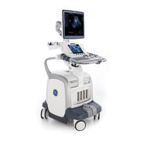
GE Vivid i Service Manual (740 pages)
Brand:
GE
| Category:
Medical Equipment
| Size: 45.83 MB
Table of Contents
Table of Contents
15
CHAPTER 1 Introduction
31
CHAPTER 2 Site Preparations
31
Overview
31
Purpose of Chapter 1
31
Purpose of Service Manual
32
Typical Users of the Service Manual (this Manual)
32
VIVID I N Models Covered in this Manual
33
VIVID Q N Models Covered in this Manual
33
System History - Hardware and Software Versions
34
Purpose of Operator Manual(S)
34
Important Conventions
35
Conventions Used in this Manual
35
Safety Considerations
37
Introduction
37
Human Safety
37
Mechanical Safety
37
Electrical Safety
39
Dangerous Procedure Warnings
41
Product Labels and Icons
42
Universal Product Labels
42
Label Descriptions
44
VIVID I N/ VIVID Q N Battery Safety
47
VIVID I N and VIVID Q N External Labels
49
Safelock Cart Labels
50
EMC, EMI, and ESD
51
Electromagnetic Compatibility (EMC)
51
CE Compliance
51
Electrostatic Discharge (ESD) Prevention
51
Standards Used
52
Lockout/Tagout (LOTO) Requirements
53
Returning/Shipping Probes and Repair Parts
54
Customer Assistance
55
Purpose of Chapter 2
57
Console Requirements
58
Unit Environmental Requirements
58
Cooling Requirements
58
Lighting Requirements
58
Time and Manpower Requirements
58
Electrical Requirements
59
EMI Limitations
60
Probe Environmental Requirements
61
Facility Needs
62
Purchaser Responsibilities
62
Mandatory Site Requirements
63
Site Recommendations
63
Networking Pre-Installation Requirements
65
Connectivity Installation Worksheet
66
Check List
68
CHAPTER 3 System Setup
69
Overview
69
Purpose of Chapter 3
69
Installation Reminders
70
Average Installation Time
70
Installation Warnings
70
Safety Reminders
71
The Tilt & Shock Indicators
72
Damage in Transportation
74
Unpacking the Equipment
77
Examin All Packages
78
Unpacking the Wooden Transportation Box
79
Verifying the Transportation Box Contents
80
Physical Inspection
80
EMI Protection
80
Preparing for Installation
81
Confirming Customer Order
81
Verifying the Transportation Box Contents
81
Component Inspection
82
Confirming Safelock Cart Voltage Configuration
87
System Voltage Confirmation
87
Ensuring Protection from EMI
88
Completing the Hardware Installation
89
Connecting Printers
89
Connecting Peripherals
102
Charging the Battery
123
Connecting Probes
126
Connecting the ECG
129
Connecting the Unit to a Power Source
130
Switching the System ON/OFF
132
Mounting the VIVID I N/ VIVID Q N on the Safelock Cart (Optional)
133
Mounting the VIVID I N and VIVID Q N on the Safelock Cart
133
Direction Fq091013, Revision
134
Adjusting the Safelock Cart Locking Mechanism
136
Configuration
137
Overview
137
VIVID I N/ VIVID Q N Configuration
138
Service Screen Set-Up
143
Configuring Peripherals
149
Software Options Configuration
152
Connectivity Setup
153
Connectivity Introduction
153
Physical Connection
156
Connectivity Configuration
166
Set up Connection to a DICOM Server in a Network
178
Setup Connection to HL7 Server in a Network
185
Query/Retrieve (Q/R) Setup
188
Mpegvue Export Configuration
195
Evue Dataflow Configuration
200
Using Mpegvue/Evue on a Remote PC
204
Storing and Transporting the Unit
245
Safety Precautions for Moving the VIVID I N/ VIVID Q N Unit
245
Transportation Box and Packaging Materials
245
Completing the Installation Paperwork
246
System Installation Details
246
Product Locator Installation
246
Product Locator Installation Card
247
User Manual(S)
248
CHAPTER 4 General Procedures and Functional Checks
249
Overview
249
Purpose of Chapter 4
249
Specific Equipment Required
250
General Procedures
251
Overview
251
Power On/Boot-Up
251
Power Shut down
255
Log on to the System as ADM
258
Using Removable Media
260
Labeling Removable Media
263
Formatting Removable Media
263
Verifying Removable Media
264
Archiving and Loading Presets
265
Functional Checks
267
Basic Controls
267
Peripherals
276
Safelock Cart Functional Tests
281
Back End Processor Tests
282
System Turnover Checklist
285
Software Configuration Checks
285
Site Log
286
CHAPTER 5 Components and Function (Theory)
289
Overview
289
Purpose of Chapter 5
289
General Information
290
Introduction
290
Signal Flow
292
VIVID I N and VIVID Q N Systems - Block Diagram
293
Front End Unit
294
General Information
294
Front End Unit - Location in the System
297
RFI Board
299
TR32 Boards (Transmitter/Receiver)
303
Probe and MUX (P&M) Board
306
Back End Processor
309
Introduction
309
ETX SBC Central Processing Unit (CPU)
311
ETX Base Board
311
Hard Disk
313
Fan Control
313
RTC (BIOS) Battery
313
Back End Processor - Location of Components
314
Left/Right Speakers
316
External Input/Output (I/O)
317
Power Supply System
318
Electrical Power
318
Introduction
318
Power Supply Unit Components
319
DC Source Selector
319
Rechargeable Battery Pack Assy (GPA)
320
Monitor and Operator Panel
322
Keyboard and Operator Panel
322
Keyboard and Operator Panel Components
323
ECG Module
327
Overview
327
ECG Patient I/O Module Specifications
328
Isolation
328
Ecg/Respiratory Module
329
Internal Ecg/Respiratory Board
329
External Ecg/Respiratory Interface
331
Peripherals
334
Introduction
334
Cooling System
336
General Information
336
CHAPTER 6 Service Adjustments
337
Overview
337
Purpose of Chapter 6
337
LCD Display Adjustments and Calibration
338
Contrast Adjustment Procedure
338
Brightness Adjustment Procedure
339
Testing Your Contrast and Brightness Settings
339
Blue Tint Adjustment Procedure
339
Blue Tint "2" Adjustment Procedure
341
External Monitor Calibration
344
Keyboard Adjustments
346
Configuring Print Orientation
346
Video System Adjustments
346
Beamformer Calibration
346
Battery Calibration
347
CHAPTER 7 Diagnostics/Troubleshooting
353
Overview
353
Purpose of Chapter
353
Diagnostics
354
Diagnostic Tools
354
Diagnostic Procedure Summary
354
Accessing the Diagnostic Test Window
355
Diagnostic Test Window Menu Options
362
Performing Full System Diagnostics
371
Accessing the Full System Diagnostic Options
372
Performing Front End (FE) Diagnostics
376
Accessing the Front End Diagnostic Options
377
Calibration Tests
377
Radio Frequency Interface (RFI) Diagnostic Tests
383
TR 32 Diagnostic Tests
398
Probe and MUX Diagnostic Tests
413
Monitoring Tests
438
Accessing the Monitoring Diagnostic Test Options
438
Performing Back End Diagnostics on the System
460
Accessing the Back End Diagnostic Test Options
460
Insite Exc
489
Service Desktop
489
Error Logs Page
491
Diagnostics Page
496
Image Quality Page
503
Calibration Page
503
Configuration Page
504
Ziputilities Page
505
Replacement Page
517
PM Page
517
Automatic Error Log
518
Adding Bookmarks
518
Extracting Logs
518
CHAPTER 8 Replacement Procedures
529
Overview
529
External Component Replacement Procedures
531
Bearing Handle Replacement Procedure
531
Battery Replacement Procedure
533
Hard Disk Replacement Procedure
535
Control Panel and Keyboard Replacement Procedure
537
Rear Cover & Latch Assembly Replacement Procedure
547
LCD Display Cover Hinges Replacement Procedure
549
Bottom Assembly Replacement Procedure
553
LCD Display Frame Replacement Procedure
555
Internal Component Replacement Procedures
557
TR32 and RFI Boards Replacement Procedure
560
BEP Replacement Procedure
566
BIOS Battery Replacement
573
HVPS Replacement Procedure
574
Fan Replacement Procedure
577
Speaker Assembly Replacement Procedure
580
LCD Display Replacement Procedure
581
LCD Flex Cable Replacement Procedure
586
Safelock Cart Components Replacement
589
Overview of Safelock Cart Replaceable Components
590
Safelock Cart Replacement Procedures - Quick Reference List
591
Upper Cover (Rear) Replacement Procedure
592
AC Cable Hook Replacement Procedure
593
AC Power Cable Bumper Protector Replacement Procedure
594
ECG Cable Protector Replacement Procedure
596
Lower Cover (Rear) Replacement Procedure
599
AC Distribution Assembly Replacement Procedure
600
Peripheral Power Cable Replacement Procedure
602
Main Cable Harness Replacement Procedure
607
USB Board Replacement Procedure
608
Gas Spring Replacement Procedure
610
DVD Holder Replacement Procedure
613
LAN Isolation Box and Holder Replacement Procedure
614
Top Shelf Replacement Procedure
615
Handrest Replacement Procedure
617
Probe Shelf Assembly Replacement Procedure
618
Probe Cable Hook Replacement Procedure
620
Front Wheel Replacement Procedure
621
Rear Wheel Replacement Procedure
623
Software Loading
625
Software Upgrade Procedure Overview
625
Setting the BIOS
636
BIOS Firmware Update
646
Formatting and Partitioning the Hard Disk - Automatic Procedure
649
Formatting and Partitioning the Hard Disk - Manual Procedure
651
Full Re-Ghost and Software Installation
656
Installing Software Only from DVD
658
Installing Software Only or Patch
662
Installation of PMC Version
663
Software Roll-Back Procedure
667
Performing a Complete System Back-Up
669
Database Merge
669
How to Restore User-Defined Presets
675
Peripherals
676
External USB Hard Disk Replacement Procedure
678
CHAPTER 9 Renewal Parts
683
Overview
683
List of Abbreviations
684
Mechanical Hardware Parts
685
Electronic Parts
686
Cables
689
Software
690
Probes
691
Peripherals
693
Safelock Cart Parts
694
Optional Modo Cart
696
Product Manuals
701
CHAPTER 10 Care and Maintenance
703
Overview
703
Periodic Maintenance Inspections
703
Warnings
704
Why Perform Maintenance Procedures
705
Keeping Records
705
Maintenance Task Schedule
706
How Often Should Care & Maintenance Procedures be Performed
706
Tools Required
709
Special Tools, Supplies and Equipment
709
System Maintenance
711
Preliminary Checks
711
Functional Checks
712
Input Power Checks
713
Cleaning
714
Physical Inspection
717
Optional Diagnostic Checks
718
Probe Maintenance
719
Probe Checks
719
Probe Handling
719
Basic Probe Care
720
Probe Cleaning
720
Returning and Shipping of Defective Probes
722
Electrical Safety Tests
723
Safety Test Overview
723
GEMS Current Leakage Limits
724
Outlet Test Wiring Arrangement - USA & Canada
725
Safelock Cart - Grounding Continuity
725
Safelock Cart - Chassis Current Leakage Test
727
Isolated Patient Lead (Source) Leakage - Lead-To-Ground
729
Isolated Patient Lead (Source) Leakage - Lead-To-Lead
730
Isolated Patient Lead (Sink) Leakage - Isolation Test
730
Probe Current Leakage Test
732
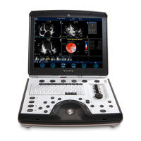
GE Vivid i User Manual (388 pages)
Brand:
GE
| Category:
Medical Equipment
| Size: 8.69 MB
Table of Contents
Table of Contents
3
Attention
11
Safety
11
Interference Caution
11
Indications for Use
12
Contraindications
12
Manual Contents
13
Finding Information
13
Conventions Used in this Manual
14
Contact Information
15
Getting Started
17
Introduction
18
Preparing the Unit for Use
19
Site Requirements
19
Connecting the Unit
20
Switching On/Off
28
Moving and Transporting the Unit
32
Moving the Unit on a Cart
32
Transporting the Unit
33
Unit Acclimation Time
33
System Description
34
System Overview
34
Control Panel
35
The Scanning Screen
45
Connecting and Disconnecting Probes
48
Adjusting the Display Monitor
51
Starting an Examination
52
Creating a New Patient Record or Starting an Examination from an Existing Patient Record
52
Selecting a Probe and an Application
56
Assignable Keys and Soft Menu Rocker
59
Using the Assignable Keys Soft Menu
60
Using the Soft Menu Rocker
63
Trackball Operation
64
Trackball Assignment
64
The System Menu
65
Cineloop Operation
66
Cineloop Overview
66
Cineloop Controls
68
Using Cineloop
69
Storing Images and Cineloops
70
To Store a Single Image
70
To Store a Cineloop
70
Using Removable Media
71
Recommendation Concerning CD and DVD Handling
71
Formatting Removable Media
71
Writing on CD or DVD Media
71
Ejecting Removable Media
73
Zoom
73
To Magnify an Image
73
Performing Measurements
73
To Perform Measurements
73
Physiological ECG Trace
74
Connecting the ECG
74
Physio Controls
75
Displaying the ECG Trace
76
Adjusting the Display of the ECG Trace
76
Annotations
77
To Insert an Annotation
77
To Edit Annotation
80
To Erase Annotation
80
Configuration of the Pre-Defined Annotation List
81
Bodymarks
83
Scanning Modes
85
Introduction
86
2D-Mode
87
2D-Mode Overview
87
2D-Mode Controls
89
Optimizing 2D
92
Using 2D
92
M-Mode
93
M-Mode Overview
93
M-Mode Controls
94
Using M-Mode
95
Optimizing M-Mode
97
Color Mode
98
Color Mode Overview
98
Color M-Mode Overview
99
Color Mode Controls
100
Using Color Mode
102
Optimizing Color Mode
103
PW and CW Doppler
104
PW and CW Doppler Overview
104
PW and CW Doppler Controls
105
Optimizing PW/CW Doppler Modes
108
Using PW/CW Doppler Modes
108
Purposely Left Empty
111
For Future Purposes
111
Contrast Imaging
113
Introduction
114
Left Ventricular Contrast Imaging
114
LV Contrast Overview
115
LV Contrast Controls
115
Optimizing LV Contrast
118
Running LV Contrast
118
Measurement and Analysis
119
Introduction
120
The Assign and Measure Modality
121
Starting the Assign and Measure Modality
121
Entering a Study and Performing Measurements
122
Measure and Assign Modality
124
Starting the Measure and Assign Modality
124
Post-Measurement Assignment Labels
125
Cardiac Measurements
127
2D Measurements
127
M-Mode Measurements
131
Doppler Measurements
134
Vascular Measurements
137
B-Mode Measurements
137
M-Mode Measurements
138
Doppler Measurements
139
Measurement Package Configuration
144
Measurement Package Configuration - Example
144
User-Defined Formulas
147
User-Defined Formula - Example
147
About Units
153
Measurement Result Table
155
Minimizing the Measurement Result Table
155
Moving the Measurement Result Table
155
Deleting Measurements
156
Worksheet
157
Overview
157
Using Worksheet
158
Purposely Left Empty
161
For Future Purposes
161
Archiving
163
Introduction
165
Storing Images and Cineloops
166
Storing a Cineloop
167
Storing an Image
167
Saving Stored Images and Cineloops to a Standard Format158
168
Saving Stored Images and Cineloops to a Standard Format
168
Mpegvue/Evue
170
Retrieving and Editing Archived Information
178
Locating a Patient Record
178
Selecting a Patient Record and Editing Data in the Archive
182
Deleting Archived Information
186
Moving Examinations
188
Review Images in Archive
191
Review the Images from a Selected Examination
191
Select Images from the Image List Screen
192
Connectivity
196
The Dataflow Concept
196
Stand-Alone Scanner Scenario
199
A Stand-Alone Scanner and a Stand-Alone Echopac PC Environment
200
VIVID I User's Manual
202
A Scanner and Echopac PC in a Direct Connect Environment
202
A Scanner and Echopac PC in a Network Environment
206
A Scanner and a DICOM Server in a Network
208
Export/Import Patient Records/Examinations
219
Exporting Patient Records/Examinations
219
Importing Patient Records/Examinations
226
Disk Management
230
Configuring the Disk Management Function
231
Running the Disk Management Function
233
Data Backup and Restore
236
DICOM Spooler
242
Starting the DICOM Spooler
242
Report
245
Introduction
246
Creating a Report
247
Working with the Report Function
247
To Print a Report
250
To Store a Report
250
Retrieving an Archived Report
251
Deleting an Archived Report
251
Direct Report
252
Creating Comments
252
Creating Pre-Defined Text Inputs
253
Report Designer
254
Accessing the Report Designer
254
Report Designer Overview
254
Designing a Report Template
257
Saving the Report Template
267
To Exit the Report Designer
268
Report Templates Management
268
Configuration of the Template Selection Menu
269
Export/Import of Report Templates
270
Probe Overview
274
Supported Probes
274
Probe Labelling
277
Probe Orientation
277
Probe Integration
279
Connecting the Probe
279
Activating the Probe
279
Disconnecting the Probe
280
Care and Maintenance
281
Planned Maintenance
281
Inspecting the Probe
282
Cleaning and Disinfecting Probes
283
Probe Safety
286
Electrical Hazards
286
Mechanical Hazards
286
Biological Hazards
287
Introduction
290
Printing
291
To Print an Image
291
Specifications for Peripherals
292
Presets and System Setup
293
Introduction
294
Starting the Configuration Package
297
To Open the Configuration Package
297
Overview
298
Imaging
299
The Global Setup Sheet
299
Application
301
Application Menu
304
Measure Text
306
The Measurement Menu Sheet
306
Configuration of the Measurement Menu
310
The Advanced Sheet
312
Parameter Configuration
312
The Modify Calculations Sheet
313
Parameter Configuration
313
Report
314
The Diagnostic Codes Sheet
315
The Comment Texts Sheet
316
VIVID I User's Manual
316
Connectivity
319
Dataflow
320
Additional Outputs
328
Tools
330
Formats
331
Tcp/Ip
336
System
337
The System Settings
337
About
339
Administration
340
Users
341
Unlock Patient
344
System Care and Maintenance
346
Inspecting the System
346
Cleaning the Unit
347
Prevention of Static Electricity Interference
349
System Self-Test
351
System Malfunction
351
Introduction
355
Owner Responsibility
356
Important Safety Considerations
357
Notice against User Modification
357
Regulatory Information
358
Standards Used
358
Device Labels
359
Label Icon Description
359
Classifications
362
Acoustic Output
363
Definition of the Acoustic Output Parameters
363
Acoustic Output and Display on the VIVID I
363
Alara
364
Safety Statement
365
System Controls Affecting Acoustic Output
365
Patient Safety
367
Patient Identification
367
Diagnostic Information
367
Mechanical Hazards
368
Personnel and Equipment Safety
369
Explosion Hazard
369
Electrical Hazard
369
Biological Hazard
370
Pacemaker Hazard
370
Electrical Safety
371
Device Classifications
371
Internally Connected Peripheral Devices
371
Internally Connected Battery
371
External Connection of Other Peripheral Devices
371
Allergic Reactions to Latex-Containing Medical Devices
372
Electromagnetic Compatibility (EMC)
373
Environmental Protection
375
System Disposal
375
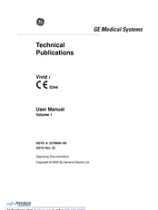
GE Vivid i Technical Publication (127 pages)
Ultrasound System
Brand:
GE
| Category:
Medical Equipment
| Size: 3.71 MB
Table of Contents
Table of Contents
21
Chapter 1 - Overview
25
Content in this Manual
26
Product Description
27
Overview of the Ultrasound System
27
Products Covered in this Manual
28
Chapter 2 - Safety Information
29
Overview
30
Contents in this Chapter
30
Important Conventions
31
Conventions Used in Book
31
Standard Hazard Icons
33
Product Icons
35
Label Icon Description
35
How to Lock the Operator Panel Prior to Transport
35
Safety Considerations
36
Introduction
36
Human Safety
36
Mechanical Safety
39
Electrical Safety
44
Label Locations
46
Product Labels
46
Dangerous Procedure Warnings
47
Warnings
47
Lockout/Tagout (LOTO)
48
LOTO Requirements
48
Returning Probes and Repair Parts
49
Requirements for Returning Parts
49
User Responsibility
49
Electromagnetic Compatibility (EMC)
50
What Is EMC
50
Compliance
50
Electrostatic Discharge (ESD) Prevention
51
Chapter 3 - Site Preparations
53
Overview
54
Contents in this Chapter
54
General Ultrasound System Requirements
55
Contents in this Section
55
Ultrasound System Environmental Requirements
55
Electrical Requirements
57
EMI Limitations
70
Probes Environmental Requirements
72
Time and Manpower Requirements
72
Facility Needs
73
Contents in this Section
73
Purchaser Responsibilities
73
Required Facility Needs
75
Desirable Features
77
Care and Maintenance
79
Contents in this Chapter
80
Chapter 4 - Care and Maintenance
81
Warnings
81
Why Do Maintenance
82
Keeping Records
82
Quality Assurance
82
Maintenance Task Schedule
83
How Often Should Maintenance Tasks be Performed
83
System Maintenance
84
Preliminary Checks
84
Functional Checks
85
Physical Inspection
87
Cleaning
89
Probe Maintenance
90
Using a Phantom
91
Phantoms
91
Electrical Safety Tests
92
Content in this Section
92
Uninterrupted Power Supply (UPS)
93
Safety Test Overview
94
Leakage Current Limits
97
Outlet Test - Wiring Arrangement - USA and Canada
101
Grounding Continuity
102
Chassis Leakage Current Test
103
Isolated Patient Lead (Source) Leakage-Lead to Ground
107
Isolated Patient Lead (Source) Leakage-Lead to Lead
109
Isolated Patient Lead (Sink) Leakage-Isolation Test
111
Probe (Source) Leakage Current Test
113
Isolated Probe (Sink) Leakage-Isolation Test
118
When There's too Much Leakage Current
122
AC/DC Fails
122
Chassis Fails
122
Probe Fails
123
Peripheral Fails
123
Still Fails
123
New Ultrasound System
123
ECG Fails
123
Ultrasound Equipment Quality Check (EQC and IQC)
124
Quality Checks
124
Related Products
GE Vivid i SafeLock Cart
GE Vivid in
GE Vivid iq
GE Vivid 3
GE VividTE7
GE Vivid q N
GE Vivid 7, Vivid E9
GE Vivid S6
GE Vivid S5
GE Vivid 4
GE Categories
Refrigerator
Ranges
Microwave Oven
Air Conditioner
Dishwasher
More GE Manuals