beautypg.com
Manuals
Brands
GE Manuals
Measuring Instruments
Sievers 500 RL
GE Sievers 500 RL Manuals
Manuals and User Guides for GE Sievers 500 RL. We have
2
GE Sievers 500 RL manuals available for free PDF download: Operation And Maintenance Manual, Quick Start Manual
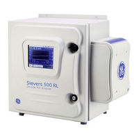
GE Sievers 500 RL Operation And Maintenance Manual (186 pages)
On-Line Total Organic Carbon Analyzer
Brand:
GE
| Category:
Measuring Instruments
| Size: 1.79 MB
Table of Contents
Identification Records
2
Table of Contents
3
List of Tables
9
List of Figures
11
Revision History
13
Trademarks and Patents
14
Confidentiality
15
Declaration of Conformity
15
Standard Limited Warranty
16
Limitation of Remedies and Liability
17
Limitación de Remedios y Responsabilidad
17
Limites de Correction et de Fiabilité
18
Beschränkte Ansprüche und Haftung
18
Limitazione DI Rimedi E Responsabilità
19
赔偿与责任限制
20
Warnings
21
Chapter 1: Introduction
37
Chapter 2: System Description
39
System Specifications
39
System Overview
41
Sample Flow Path
42
Analyzer Schematic (Shown with Standard Ios)
42
Additional System Components
44
Microprocessor Controller and Electronics
44
Data Outputs
44
Chapter 3: Installation
45
Overview
45
Step 1: Unpack and Inspect the Analyzer
46
Additional Installation Equipment
47
Step 2: Complete the Identification Records
47
Step 3: Select a Location for the Analyzer
47
Step 4: Install Power and Control Wiring
48
Connecting to a Power Supply
48
Installing the Analog Outputs and Alarms
49
Wiring AC Power
49
Alarm Outputs (TB2)
50
Table 3 Serial and 4-20 Ma Outputs (TB3)
51
Figure 4 Wiring Option for Binary Input Using Analyzer's Internal Supply
52
Figure 5 Wiring Option for Binary Input Using External Supply
53
Installing the Printer
54
Installing the Serial Connection
54
Installing the USB Connection
54
Step 6: Connect the Sample Inlet and Outlet Ports
55
Wiring the Ethernet Cable
55
Step 7: Fill the DI Water Cartridge
56
Wiring the Remote Start (Binary Input) Connection
52
Step 5: Installing the Printer, USB, and Serial Connections
53
Wiring the 4-20 Ma Connection
51
Alarm Outputs (TB1)
50
Filling the DI Water Cartridge
57
Removing the John Guest Fitting
58
Step 8: Configure Basic Analyzer Settings
59
Enabling Dataguard or Password Protection (Optional)
59
Enabling Password Protection
59
Enabling Dataguard
60
Establishing a New Administrator Account for Dataguard
61
Setting the Clock and Time Zone
61
Naming the Analyzer Location (Optional)
62
Setting the Analyzer Mode
62
Setting up the Data History
62
Setting up the Printer (Optional)
63
Exporting and Printing System Settings
63
Set up Data I/O
64
Step 9: Rinsing the Analyzer
64
Step 10: Install Datashare 500 Software
65
Chapter 4: Basic Analyzer Operation
67
Overview
67
The Main Screen
67
Figure 10 the Sievers 500 RL On-Line TOC Analyzer Main Screen
68
Setup
69
Setting the Analyzer Mode
69
Grab Mode Measurement Settings
70
The Setup Tab
70
Taking TOC Measurements
69
The Menu Screen
69
Managing Data History
71
Setting up Data History
71
The Data Tab
71
Archiving Data History
72
Viewing Data History
72
Graphing Data History
74
Printing Data History
75
Exporting Data History
76
Setting up Analyzer Input and Output
76
Setting up Analog Output
77
Adjusting Analog Output Values
78
Setting up Serial Output
78
Interpreting Serial Output
79
Issuing Serial Commands to the Analyzer
80
Configuring Printer Settings
80
Activating Binary Input
81
Setting Alarm Values
81
Using the Ethernet Connection and Modbus
82
Table 4 Data Fields Output to the Serial (RS-232) Port
79
Managing Maintenance Information
85
Displaying Consumables Status
86
Setting the Analyzer Clock and Time Zone
86
Reviewing Warnings and Errors
87
Displaying System Information
88
Advanced Analyzer Settings
88
Exporting or Printing the Warning and Error History
88
Figure
83
Table
83
Table
84
Figure 18 the Advanced Menu with One Program Language Loaded
88
Printing the Constants Values
89
Saving System Settings
89
Adjusting Display Contrast Settings
90
Changing the Display Mode
90
Naming the Analyzer Location
90
Specifying the Pharmacopeia
91
Pharmacopeia Options
91
Pass/Fail Reporting
92
Configuring the Flow Sensor
93
Selecting the Program Language
93
Programming the TOC Autozero
94
Specifying Auto Restart Settings
94
Activating Additional Features
95
Draining the Ios System
95
Basic Hardware Operation Issues
96
Opening the Analyzer Case
96
The Touch Screen
96
Recommended Operational State
96
The Ios System
96
The Super Ios System
98
Vial Set Cartridges
99
Steam Exposure
99
The Sample Inlet Block
98
Chapter 5: Password Protection and Dataguard
101
Overview
101
Figure 22 Menu Map - Menu Lockout off (Requires Calibration Passwords)
102
Enabling Password Protection
103
Menu Map - Dataguard (Optional Upgrade)
103
To Change the Password
104
To Configure Password Settings
104
To Enable Password Protection
104
Disabling Password Protection
105
Using Dataguard
105
Enabling Dataguard
105
Adding User Ids
106
Editing User Information
107
Configuring Login Settings
108
Changing User Passwords
108
Dealing with Forgotten Passwords
108
Reactivating Inactivated User Accounts
109
Archiving User Accounts
109
Viewing, Exporting, and Printing Audit Trails
110
Audit Trail Output Format
110
Logging out
111
Chapter 6: Calibration and System Protocols
113
Overview
113
Required Calibration Supplies
114
Table 8 Standards Required for Single-Point Calibration
114
Table 9 Standards Required for Multi-Point Calibration
114
Figure 27 the Second Summary Screen in a Multi-Point Calibration
123
Figure
126
Figure 30 the Accuracy, Precision, and Verification Summary Screen, Part 2
126
Performing Pharmacopeia Tests
127
System Suitability Verification
127
JP Protocol
129
Reviewing Calibration and Verification History
132
High Blank TOC Warnings/Errors
133
Single-Point Calibration Worksheet
134
Multi-Point Calibration Worksheet
135
Accuracy, Precision, and Verification Worksheet
136
System Suitability Worksheet
137
JP Protocol Worksheet
138
Preparing for Calibration
115
Save System Settings
115
Table 10 Standards Required for Accuracy, Precision, and Verification
115
Figure 24 Reviewing TC and IC Values from a Single-Point Calibration
119
Figure 25 Reviewing Conductivity Values from a Single-Point Calibration
119
Figure 26 the First Summary Screen in a Multi-Point Calibration
122
Figure 28 the Third Summary Screen in a Multi-Point Calibration
123
Accuracy, Precision, and Calibration Verification
124
Table 11 Standards Required for System Suitability Verification
115
Performing a Multi-Point Calibration
120
Disable Daily Download and Binary Input
116
Handling Standards
116
Perform Annual Maintenance Tasks
116
Performing a Single-Point Calibration
117
Figure 29 the Accuracy, Precision, and Verification Summary Screen, Part 1
126
Chapter 7: Maintenance
139
Replacing Consumables and Maintenance Items
139
Checking and Refilling the DI Water Level
140
Replacing the UV Lamp
141
Figure 34 Relative Positioning of Components in the UV Lamp Assembly
143
Figure 37 John Guest Fittings on the DI Water Cartridge (Detail)
147
Replacing the In-Line Filter Element
148
Setting the Installation or Date for New Consumables
149
Cleaning the Analyzer
150
Replacing the Sample Pump Tubing and Pump Heads
144
Replacing the DI Water Cartridge
145
Table 15 Sievers 500 RL On-Line TOC Analyzer 3-Year Maintenance Worksheet
151
Chapter 8: Troubleshooting
153
Overview
153
Step 1: Review Warnings and Errors
153
Warnings and Error Messages
154
Step 2: Visual Inspection
159
External Inspection
159
Internal Inspection
159
Step 3: Review Solutions for Basic Problems
159
The Analyzer will Not Power on
160
No Flow through the Analyzer
160
Backflushing the Analyzer
160
Checking the Sample Pump
160
Confirm Flow of Water to the Analyzer
160
Figure 40 Disconnecting the Tubing from the Front Solenoid Valve
161
Figure 41 the Inlet and Outlet Connections Inside the Analyzer
162
Negative, High, or Erratic Measurements
163
Conductivity Autozero
163
Sample Conductivity Cell Calibration
163
Sample Cell Zero
164
TOC Autozero
164
TOC Offset
165
Problems Changing the Program Language
165
Problems with the DI Water Pump
166
Problems with Vial Set Cartridges
166
Step 4: Contact Technical Support
167
Step 5: Return the Analyzer to GE Analytical Instruments
167
Figure 45 Analyzer Dimensions, with Standard Ios System
171
Appendix A: Analyzer Dimension Diagrams
171
Figure 46 Right-Side Analyzer Dimensions, with Standard Ios System
172
Figure 48 Right-Side Analyzer Dimensions, with Super Ios System
174
Figure 50 Right-Side Analyzer Dimensions, with Sample Inlet Block
176
Appendix B: Connecting to a PC
179
Using Hyperterminal
179
Determining Your Communications Port Number
180
Index
181
GE Sievers 500 RL Quick Start Manual (8 pages)
TOC Analyzers
Brand:
GE
| Category:
Measuring Instruments
| Size: 0.57 MB
Table of Contents
Aviso Importante
2
Avviso Importante
6
Guida Rapida
6
Guide de Démarrage Rapide
8
Related Products
GE 5176/200
GE Precision 500D
GE MAC 5 A4
GE MAC 5 A5
GE Sievers 900 Series
GE 500A436P006
GE keysafe consumer 500
GE 500PAR64/NSP
GE 500PAR64/MFL
GE 500PAR64/WFL
GE Categories
Refrigerator
Ranges
Microwave Oven
Air Conditioner
Dishwasher
More GE Manuals