GE Multilin 889 Manuals
Manuals and User Guides for GE Multilin 889. We have 2 GE Multilin 889 manuals available for free PDF download: Instruction Manual
GE Multilin 889 Instruction Manual (580 pages)
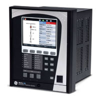
Generator Protection System
Brand: GE
|
Category: Protection Device
|
Size: 14.84 MB
Table of Contents
-
-
Device22
-
Protection22
-
Control30
-
Monitoring32
-
Recording34
-
Metering36
-
Inputs37
-
Outputs39
-
Power Supply40
-
Physical43
-
-
-
Storage48
-
-
-
Repairs48
-
Dimensions50
-
Mounting51
-
-
-
-
-
File Support104
-
Quick Setup110
-
-
Common Setpoints133
-
Logic Diagrams134
-
Device136
-
Real-Time Clock138
-
Clock140
-
SNTP Protocol142
-
Security143
-
Basic Security144
-
Cybersentry146
-
-
Communications153
-
Modbus Protocol153
-
Rs485158
-
Wifi158
-
Usb161
-
Ethernet Ports161
-
Routing163
-
DNP Protocol166
-
Iec 60870-5-104170
-
Iec 60870-5-103172
-
Iec 61850172
-
-
Data Logger178
-
Fault Reports180
-
Event Data182
-
Flex States182
-
Front Panel182
-
Tab Pushbuttons188
-
Annunciator191
-
Default Screens194
-
Home Screens195
-
Resetting196
-
Installation196
-
System198
-
Current Sensing198
-
Voltage Sensing199
-
Traditional VT199
-
-
Power Sensing200
-
Power System201
-
Generator202
-
Setup202
-
-
Transformer203
-
Windings204
-
-
Breakers216
-
Switches218
-
Flexcurves221
-
-
Inputs223
-
Contact Inputs223
-
Virtual Inputs226
-
Analog Inputs228
-
Remote Inputs232
-
-
Outputs233
-
Protection242
-
Current Elements286
-
Voltage Elements348
-
-
Out-Of-Step (78)375
-
-
Power Elements381
-
Monitoring400
-
Generator401
-
Breaker412
-
Breaker Health423
-
Functions427
-
Power Factor427
-
Demand432
-
Pulsed Outputs440
-
Digital Counters443
-
-
Speed449
-
RTD Temperature454
-
RTD Trouble459
-
-
Control462
-
Setpoint Group463
-
Generator465
-
Breaker Control479
-
Trip Bus485
-
-
Flexlogic502
-
Timers512
-
Flexelements517
-
-
Testing523
-
Simulation524
-
Setup524
-
Pre-Fault525
-
Fault526
-
Post-Fault527
-
-
Test Leds527
-
Contact Inputs528
-
Output Relays528
-
Configurable SLD532
-
STATUS Summary532
-
Annunciator533
-
Tab Pushbuttons533
-
-
Generator534
-
Breakers536
-
Switches536
-
Last Trip Data536
-
Arc Flash537
-
Contact Inputs537
-
Output Relays537
-
Virtual Inputs537
-
Virtual Outputs538
-
Flex State539
-
Communications539
-
GOOSE Rx and Tx539
-
-
Information543
-
Comms CPU543
-
Environment544
-
-
Device Status545
-
Clock546
-
PTP Status546
-
Metering
547-
METERING Summary550
-
Generator551
-
Impedance554
-
Currents554
-
Voltages556
-
Frequency558
-
Volts Per Hertz558
-
Synchrocheck560
-
Power561
-
Energy562
-
Power Factor563
-
Current Demand 1563
-
Power Demand564
-
Arc Flash565
-
Rtds565
-
RTD Maximums566
-
Analog Inputs566
-
Flexelements566
-
RECORDS Events567
-
Data Logger568
-
Fault Reports568
-
Breakers569
-
Breaker Health569
-
Digital Counters569
-
Clear Records572
-
-
Warranty
577-
Major Updates578
-
GE Multilin 889 Instruction Manual (38 pages)
Multilin 8 Series
Brand: GE
|
Category: Control Panel
|
Size: 1.88 MB