beautypg.com
Manuals
Brands
GE Manuals
Protection Device
869
GE 869 Manuals
Manuals and User Guides for GE 869. We have
3
GE 869 manuals available for free PDF download: Instruction Manual, Communications Manual
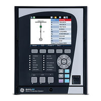
GE 869 Instruction Manual (606 pages)
Motor Protection System
Brand:
GE
| Category:
Security Sensors
| Size: 15.67 MB
Table of Contents
Table of Contents
3
INTRODUCTION Overview
11
Description of the 869 Motor Protection System
12
Security Overview
17
Order Codes
18
Specifications
21
Control
30
Monitoring
31
Recording
33
User-Programmable Elements
34
Metering
35
Inputs
37
Outputs
38
Power Supply
40
Testing & Certification
41
Physical
42
Cautions and Warnings
43
Must-Read Information
46
Storage
47
INSTALLATION Mechanical Installation
49
Dimensions
50
Mounting
51
Standard Panel Mount
52
Depth Reducing Collar
53
Draw-Out Unit Withdrawal and Insertion
55
Removable Power Supply
56
Removable Magnetic Module
57
Arc Flash Sensor
58
Electrical Installation
59
Terminal Identification
62
Wire Size
66
Phase Sequence and Transformer Polarity
67
Ground and Sensitive Ground CT Inputs
68
Zero-Sequence CT Installation
69
Differential CT Inputs
70
Voltage Inputs
71
Control Power
72
Contact Inputs
73
Serial Communications
75
Irig-B
77
INTERFACES Front Control Panel Interface
80
Working with Graphical Display Pages
82
Single Line Diagram
84
Rugged and Membrane Front Panel Leds
86
Home Screen Icons
88
Relay Messages
89
Self-Test Errors
90
Out of Service
93
Software Interface
95
Installing the Enervista 8 Series Setup Software
96
Upgrading the Software
98
Connecting Enervista 8 Series Setup Software to the Relay
99
Configuring Ethernet Communications
100
Connecting to the Relay
101
Working with Setpoints & Setpoints Files
102
Engaging a Device
103
File Support
104
Downloading & Saving Setpoints Files
105
Creating a New Setpoints File
106
Upgrading Setpoints Files to a New Revision
107
Printing Setpoints
108
Loading Setpoints from a File
109
Quick Setup
110
Upgrading Relay Firmware
112
Loading New Relay Firmware
113
Advanced Enervista 8 Series Setup Software Features
116
Flexcurve Editor
123
Transient Recorder (Waveform Capture)
124
Protection Summary
128
Offline Settings File Conversion
130
Convert 369 Files
131
Results Window
132
SETPOINTS Setpoints Main Menu
133
Setpoints Entry Methods
134
Common Setpoints
135
Logic Diagrams
136
Setpoints Text Abbreviations
137
Device
138
Custom Configuration
139
Real-Time Clock
141
Clock
143
SNTP Protocol
144
Security
145
Basic Security
146
Cybersentry
148
Communications
155
Rs485
160
Ethernet Ports
163
Routing
165
DNP Protocol
168
DNP / IEC104 Point Lists
169
Iec 60870-5-104
172
Iec 60870-5-103
173
Iec 61850
174
Remote Modbus Device
177
Transient Recorder
178
Data Logger
180
Fault Reports
182
Event Data
184
Programmable Pushbuttons
185
Tab Pushbuttons
190
Annunciator
193
Display Properties
195
Default Screens
196
Home Screens
197
Resetting
198
System
200
Voltage Sensing
201
Power System
202
Motor
203
Variable Frequency Drives
208
Preset Values
213
Switching Device
214
Contactor
216
Flexcurves
218
Inputs
220
Virtual Inputs
223
Analog Inputs
225
Remote Inputs
229
Outputs
230
Output Relay 1 (F1) Trip
232
Output Relay 2 (F4) Programmed as Close
234
Auxiliary Output Relays
236
Output Relay 3 (F7) Start Inhibit
238
Analog Outputs
239
Protection
240
Motor Elements
242
Thermal Model (49)
249
Current Unbalance (46)
270
Mechanical Jam (50LR)
275
Undercurrent (37)
278
Loss of Excitation (40)
281
Overload Alarm
287
Short Circuit
289
Ground Fault (50SG)
292
Acceleration Time
296
Underpower (37P)
299
Speed Motor
302
Speed Acceleration
303
Speed Undercurrent
306
Current Elements
308
Percent of Load-To-Trip
315
Phase Time Overcurrent Protection (51P)
316
Phase Instantaneous Overcurrent Protection (50P)
319
Phase Directional Overcurrent Protection (67P)
321
Neutral Time Overcurrent Protection (51N)
324
Neutral Instantaneous Overcurrent Protection (50N)
327
Neutral Directional Overcurrent Protection (67N)
330
Ground Time Overcurrent Protection (51G)
335
Ground Instantaneous Overcurrent Protection (50G)
337
Negative Sequence Instantaneous Overcurrent Protection (50_2)
339
Voltage Elements
342
Phase Reversal (47)
343
Undervoltage Curves
345
Phase Undervoltage Protection (27P)
346
Phase Overvoltage Protection (59P)
349
Auxiliary Undervoltage (27X)
352
Auxiliary Overvoltage Protection (59X)
355
Neutral Overvoltage Protection (59N)
358
Negative Sequence Overvoltage Protection (59_2)
361
Volts Per Hertz (24)
363
Impedance Elements
368
Out-Of-Step (78)
370
Power Elements
375
Directional Power (32)
376
Reactive Power (40Q)
381
Frequency Elements
384
Overfrequency (81O)
387
Frequency Rate of Change (81R)
390
Monitoring
394
Breaker Arcing Current
402
Breaker Health
405
Broken Rotor Bar
409
Electrical Signature Analysis (ESA)
414
Stator Inter-Turn Fault
425
Functions
429
Demand
434
Pulsed Outputs
442
Digital Counters
445
Harmonic Detection
448
Speed
451
RTD Temperature
456
RTD Trouble
461
Loss of Communications
462
Control
464
Start Supervision
467
Thermal Inhibit
468
Maximum Starting Rate
470
Time between Starts
472
Restart Delay
473
Reduced Voltage Starting
474
Local Control Mode (Breakers and Switches)
478
Breaker Control
488
Contactor Control
491
Switch Control (9)
494
Virtual Input Control
497
Trip Bus
498
Breaker Failure (50BF)
500
Setup
501
Initiate
503
Arc Flash Protection
505
VT Fuse Failure (VTFF)
507
Flexlogic
509
Timers
519
Flexlogic Equation
520
Viewing Flexlogic Graphics
522
Flexelements
523
Testing
531
Setup
532
Fault
533
Post-Fault
534
Test Leds
535
Ethernet Loopback Test
536
STATUS Summary
540
Annunciator
541
Motor
543
Breakers
545
Last Trip Data
546
Output Relays
547
Virtual Outputs
548
Communications
549
Information
553
Environment
554
Device Status
555
Clock
556
METERING Summary
560
Motor
561
Speed
562
Stator Inter-Turn Fault
563
Short Circuit
565
Impedance
566
Voltages
568
Frequency
569
Harmonics 1(Harmonics 2)
570
Harmonic Detection
571
Power
572
Energy
573
Power Factor
574
Power Demand
575
Arc Flash
576
RTD Maximums
577
RECORDS Events
579
Transient Records
580
Motor Start Statistics
581
Learned Data
582
Remote Modbus Device
586
Breakers
588
Remote Modbus Device
589
Clear Records
591
Environmental Health Report
593
Motor Health Report
595
General Maintenance
598
Application Notes
599
A.APPENDIX a Application Notes
601
Warranty
601
B.APPENDIX B Warranty
602
Major Updates
602
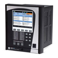
GE 869 Instruction Manual (552 pages)
Motor Protection System/Motor Protection, Control and Management
Brand:
GE
| Category:
Protection Device
| Size: 12.25 MB
Table of Contents
Table of Contents
3
INTRODUCTION Overview
11
Description of the 869 Motor Protection System
12
Security Overview
16
Order Codes
17
Specifications
19
Control
27
Monitoring
28
Recording
29
User-Programmable Elements
31
Metering
32
Inputs
34
Outputs
36
Power Supply
37
Communications
38
Physical
40
General Cautions and Warnings
41
Must-Read Information
43
Storage
44
INSTALLATION Mechanical Installation
45
Dimensions
46
Mounting
47
Standard Panel Mount
48
Draw-Out Unit Withdrawal and Insertion
49
Removable Power Supply
50
Removable Magnetic Module
51
Arc Flash Sensor
52
Electrical Installation
53
Terminal Identification
56
Wire Size
61
Ground and Sensitive Ground CT Inputs
62
Zero-Sequence CT Installation
63
Differential CT Inputs
64
Voltage Inputs
65
Control Power
66
Contact Inputs
67
Output Relays
68
Serial Communications
70
Irig-B
71
INTERFACES Front Control Panel Interface
74
Working with Graphical Display Pages
75
Single Line Diagram
78
LED Status Indicators
79
Home Screen Icons
80
Relay Messages
81
Self-Test Errors
82
Out of Service
86
Software Interface
87
Installing the Enervista 8 Series Setup Software
88
Upgrading the Software
90
Configuring Ethernet Communications
92
Connecting to the Relay
93
Working with Setpoints & Setpoints Files
94
File Support
96
Downloading & Saving Setpoints Files
97
Creating a New Setpoints File
98
Printing Setpoints
99
Loading Setpoints from a File
100
Uninstalling Files and Clearing Data
101
Upgrading Relay Firmware
104
Advanced Enervista 8 Series Setup Software Features
107
Transient Recorder (Waveform Capture)
108
Protection Summary
112
Offline Settings File Conversion
114
Convert 369 Files
115
Results Window
116
SETPOINTS Setpoints Main Menu
119
Setpoints Entry Methods
120
Common Setpoints
121
Logic Diagrams
122
Setpoints Text Abbreviations
123
Device
124
Custom Configuration
125
Real-Time Clock
127
Clock
129
SNTP Protocol
130
Security
131
Basic Security
132
Cybersentry
134
Communications
141
Rs485
146
Ethernet Ports
149
Routing
151
DNP Protocol
154
DNP / IEC104 Point Lists
155
Iec 60870-5-104
158
Iec 60870-5-103
159
Iec 61850
160
Remote Modbus Device
162
Transient Recorder
164
Data Logger
166
Fault Reports
168
Event Data
170
Programmable Pushbuttons
173
Front Panel
177
Default Screens
178
Installation
179
System
180
Current Sensing
181
Voltage Sensing
182
Power System
183
Motor
184
Variable Frequency Drives
189
Preset Values
194
Switching Device
195
Flexcurves
198
Inputs
200
Virtual Inputs
203
Analog Inputs
205
Remote Inputs
210
Outputs
211
Output Relay 1 (F1) Trip
212
Output Relay 2 (F4) Programmed as Close
215
Auxiliary Output Relays
216
Output Relay 3 (F7) Start Inhibit
217
Virtual Outputs
218
Analog Outputs
219
Protection
221
Motor Elements
223
Thermal Model
230
Current Unbalance
252
Mechanical Jam
257
Undercurrent
260
Loss of Excitation
263
Overload Alarm
269
Short Circuit
271
Ground Fault
274
Acceleration Time
278
Underpower
281
Speed Motor
284
Speed2 Acceleration
286
Speed2 Undecurrent
288
Current Elements
290
Percent of Load-To-Trip
298
Phase Instantaneous Overcurrent Protection
302
Phase Directional Overcurrent Protection
304
Neutral Time Overcurrent Protection
307
Neutral Instantaneous Overcurrent Protection
310
Neutral Directional Overcurrent Protection
313
Ground Time Overcurrent Protection
318
Ground Instantaneous Overcurrent Protection
320
Negative Sequence Instantaneous Overcurrent Protection
322
Voltage Elements
325
Undervoltage Curves
328
Phase Undervoltage Protection
329
Phase Overvoltage Protection
332
Auxiliary Undervoltage
335
Auxiliary Overvoltage Protection
338
Neutral Overvoltage Protection
341
Negative Sequence Overvoltage Protection
344
Volts Per Hertz
346
Impedance Elements
352
Power Elements
358
Reactive Power
364
Frequency Elements
367
Overfrequency
370
Frequency Rate of Change
373
Monitoring
377
Breaker Arcing Current
385
Breaker Health
388
Broken Rotor Bar
392
Stator Inter-Turn Fault
397
Functions
402
Demand
407
Pulsed Outputs
415
Digital Counters
418
Harmonic Detection
422
Speed
425
RTD Temperature
430
RTD Trouble
435
Loss of Communications
436
Control
438
Start Supervision
441
Maximum Starting Rate
444
Time between Starts
445
Restart Delay
447
Reduced Voltage Starting
448
Switching Device Control
452
Trip Bus
455
Breaker Failure
457
Setup
458
Initiate
460
Arc Flash Protection
462
VT Fuse Failure
464
Flexlogic
466
Timers
475
Non-Volatile Latches
476
Flexlogic Equation
477
Viewing Flexlogic Graphics
479
Flexelements
480
Testing
488
Setup
489
Pre-Fault
490
Post-Fault
491
Test Leds
492
STATUS Motor
493
Breakers
495
Last Trip Data
496
Output Relays
497
Virtual Outputs
498
Communications
499
Information
502
Hardware Versions
503
Device Status
504
Clock
505
METERING Summary
510
Motor
511
Speed
512
Stator Inter-Turn Fault
513
Impedance
514
Voltages
516
Frequency
517
Harmonics 1(Harmonics 2)
518
Harmonic Detection
519
Power
520
Energy
521
Power Factor
522
Power Demand
523
Rtds
524
Analog Inputs
525
RECORDS Events
527
Transient Records
528
Motor Start Records
529
Motor Start Statistics
530
Remote Modbus Device
533
Breakers
535
Remote Modbus Device
536
MAINTENANCE Environmental Health Report
539
Motor Health Report
541
General Maintenance
544
A.APPENDIX a Application Notes
545
Contactor Current Supervision
545
Warranty
547
Major Updates
548
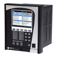
GE 869 Communications Manual (436 pages)
Motor Protection System, Control and Management
Brand:
GE
| Category:
Protection Device
| Size: 2.48 MB
Table of Contents
Table of Contents
3
1 Introduction
5
Communications
5
For Further Assistance
5
2 Communication Ports
7
RS485 Port
7
Rs485
7
Wifi
8
Wifi Quick Start Procedure
10
Usb
11
Using the Quick Connect Feature Via the USB Port
12
Ethernet Ports
12
Network Settings Menu
13
Routing
14
3 Time Protocols
19
Real-Time Clock
19
IEEE 1588 Precision Time Protocol (PTP)
19
PTP Status
19
PTP Configuration
21
Clock
23
Irig-B
24
4 Dnp
25
DNP Communication
25
DNP Device Profile
29
DNP Implementation
32
5 Dnp / Iec104 Point Lists
37
6 Iec 60870-5-104
41
Interoperability
43
7 Iec 60870-5-103
51
Cause of Transmission
51
Communications Menus
52
Interoperability
54
Physical Layer
54
Electrical Interface
54
Optical Interface
54
Transmission Speed
54
Link Layer
54
Application Layer
55
Selection of Standard Information Numbers in Control Direction
57
Basic Application Functions
58
Miscellaneous
58
8 Iec 61850
59
General
59
Functionality
62
The IEC 61850 Configurator
62
Online and Offline Setup
62
IEC 61850 Configurator Details
64
ICD/CID
65
Settings
67
Reports
70
Goose Transmission
76
Goose Reception
80
9 File Transfer Protocols
83
Modbus Protocol
85
Administrator Login and Commands Via Modbus for 8 Series Relays
91
11 Modbus Memory Map
95
Reading the Event Recorder
95
Reading Transient Recorder
95
Reading Fault Reports
96
Accessing Data Via the User Map
96
Memory Map Organization
97
MODBUS Memory Map
97
Format Codes
240
Modbus Commands
433
12.Appendix a
435
Warranty
435
Revision History
435
Major Updates
435
Related Products
GE Multilin 850
GE 845
GE Multilin 889
GE 862A725P80
GE Spacemaker 862A300P121
GE Spacemaker 862A300PI
GE Spacemaker 862A725P23
GE Bluetooth Headset 86712
GE Sport Headset 86711
GE Bently Nevada 86517
GE Categories
Refrigerator
Ranges
Microwave Oven
Air Conditioner
Dishwasher
More GE Manuals