beautypg.com
Manuals
Brands
GE Manuals
Single board computers
IMP2B
GE IMP2B Manuals
Manuals and User Guides for GE IMP2B. We have
1
GE IMP2B manual available for free PDF download: Hardware Reference Manual
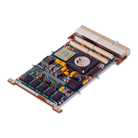
GE IMP2B Hardware Reference Manual (55 pages)
Brand:
GE
| Category:
Single board computers
| Size: 2.37 MB
Table of Contents
Table of Contents
4
1 Overview
8
Features
8
Figure 1-1 View of IMP2B
9
2 Configuration
10
Link Functions
10
Table 2-1 Link Functions
10
Figure 2-1 Link Positions (Top)
10
Suggested Link Settings
11
Factory Test Link (P1)
11
Flash Boot Image Select Links (P2 1-2 and 3-4)
11
Table 2-2 Suggested Link Settings
11
Table 2-3 Links P2 1-2 and 3-4
11
Backplane Flash Programming Link (P2 5-6)
12
Flash Protection Password Unlock Link (P3 1-2)
12
Table 2-4 Link P2 5-6
12
Table 2-5 Link P3 1-2
12
Boot Flash Write Enable Link (P3 3-4) and User Flash Write Enable Link (P3 5-6)
13
JTAG Scanbridge Enable Link (P4 1-2)
13
Table 2-6 Links P3 3-4 and 5-6
13
Table 2-7 Link P4 1-2
13
Backplane JTAG Buffer Enable Link (P4 3-4)
14
Backplane JTAG Auto-Write Enable Link (P4 5-6)
14
Force 33 Mhz Operation Link (P5 1-2)
14
Table 2-8 Link P4 3-4
14
Table 2-9 Link P4 5-6
14
Table 2-10 Link P5 1-2
14
Nvram/Serial EEPROM Write Enable Link (P5 3-4)
15
Spare Link (P5 5-6)
15
Special Linking Requirements
15
Table 2-11 Link P5 3-4
15
3 Functional Description
16
Powerpc Processor
16
Figure 3-1 Block Diagram
16
Host Bridge
17
Ram
18
Non-Volatile RAM (NVRAM)
18
Table 3-1 SDRAM Options
18
Flash Memory
19
Boot Flash
19
Table 3-2 Flash Options
19
Table 3-3 Boot Image Selection
19
User Flash
20
Flash Sector Protection
20
Memory Map Set up by Vxworks (as Seen by CPU)
21
PMC Site
21
Table 3-4 Vxworks Card-Level Memory Map
21
Table 3-5 PMC Site IDSEL Connections
21
Limited Host, Full PMC User I/O' Mode
22
Peripheral Only' Mode
22
PMC Rear I/O Tracking
22
Alternative PMC I/O' Mode
23
Table 3-6 Alternative PMC I/O Mode Signals
23
Serial Ports
24
Table 3-7 Signal Sets Per Port in Available Modes
24
Figure 3-2 RS422/485 Signal Definition
24
Ethernet
25
Usb 2.0
25
Timers
25
Watchdog Timer
25
DMA Engines
26
I 2 C Interface
26
Serial EEPROM
26
Real-Time Clock
26
Table 3-8 I 2 C Device Addresses
26
Elapsed Time Indicator
27
Temperature Sensing
27
Epld
28
Internal EPLD Registers
28
Table 3-9 EPLD Registers
28
Board ID Register 1 - Offset 0X00000000
29
Board ID Register 2 - Offset 0X00000002
29
Device/Bus Information Register 1 - Offset 0X00000004
29
Table 3-10 Board ID Register 1
29
Table 3-11 Board ID Register 2
29
Table 3-12 Device/Bus Information Register 1
29
Device/Bus Information Register 2 - Offset 0X00000006
30
Configuration Register 1 - Offset 0X00000008
30
Table 3-13 Device/Bus Information Register 2
30
Table 3-14 Configuration Register 1
30
Configuration Register 2 - Offset 0X0000000A
31
Control Register 1 - Offset 0X0000000C
31
Table 3-15 Configuration Register 2
31
Table 3-16 Control Register 1
31
Control Register 2 - Offset 0X0000000E
32
Test Registers
32
Scratchpad Registers
32
Table 3-17 Control Register 2
32
Table 3-18 Test Registers
32
Table 3-19 Scratchpad Registers
32
EPLD Interrupt Register - Offset 0X00000020
33
Software Reset Register - Offset 0X00000040
33
Table 3-20 EPLD Interrupt Register
33
Table 3-21 Software Reset Register
33
Semaphore Register - Offset 0X00000060
34
General Purpose I/O Controller
34
Table 3-22 Semaphore Register
34
GPIO Data Register - Offset 0X00000402
35
GPIO Direction Control Register - Offset 0X00000400
35
GPIO Interrupt Mode Register - Offset 0X00000406
35
GPIO Polarity Control Register - Offset 0X00000404
35
Table 3-23 GPIO Line to Register Bit Mapping
35
GPIO Interrupt Active Register - Offset 0X00000408
36
GPIO Interrupt Enable Register - Offset 0X0000040A
36
GPIO Masked Interrupt Status Register - Offset 0X0000040C
36
Compactpci Arbiter
36
Resets
37
Table 3-24 Reset Causes
37
Interrupts
38
Table 3-25 Interrupt Mapping
38
Table 3-26 Interrupt Combination
38
Jtag
39
Table 3-27 JTAG Chains
39
Leds
40
Table 3-28 Leds
40
Figure 3-3 LED Positions
40
Front Panel
41
Table 3-29 BIT Status Leds
41
Figure 3-4 Front Panel
41
4 Connectors
42
Table 4-1 Connector Functionality
42
Figure 4-1 Connector Positions
42
J2 Connector Pinout
43
System Controller Card (IMP2B-Xxxxa)
43
Table 4-2 J2 Pinout (System Controller)
43
Peripheral Only Card (IMP2B-Xxxxb)
44
Table 4-3 J2 Pinout (Peripheral Only)
44
Limited Host, Full PMC User I/O Card (IMP2B-XXXXD)
45
Table 4-4 J2 Pinout (Limited Host, Full PMC User I/O)
45
System Controller Card - Alternative PMC I/O (IMP2B-Xxxxe)
46
Table 4-5 J2 Pinout (System Controller- Alternative PMC I/O)
46
J2 Connector Signal Descriptions
47
PMC Rear I/O Tracking
47
JTAG Test Header (P38)
47
Table 4-6 J2 Signal Descriptions
47
A • Specifications
48
Technical Specification
48
Table A-1 Technical Specification
48
Electrical Specification
49
Table A-2 Voltage Supply Requirements
49
Table A-3 Power Dissipation
49
Weight
50
Reliability (MTBF)
50
Table A-4 Reliability (MTBF)
50
Product Codes
51
Software Support
51
Table A-5 Product Codes
51
Development Tools
52
I/O Modules
52
Index
53
Related Products
GE IM-4A
GE IM4D
GE IM4LED
GE IM-5SS
GE IM4
GE IM6
GE IM-5D
GE Moisture Image 1 Series
GE IM-6D
GE imagine
GE Categories
Refrigerator
Ranges
Microwave Oven
Air Conditioner
Dishwasher
More GE Manuals