Fujitsu PRIMERGY TX120 S3 Manuals
Manuals and User Guides for Fujitsu PRIMERGY TX120 S3. We have 2 Fujitsu PRIMERGY TX120 S3 manuals available for free PDF download: Upgrade And Maintenance Manual, Operating Manual
Fujitsu PRIMERGY TX120 S3 Upgrade And Maintenance Manual (440 pages)
Table of Contents
-
-
-
Viewing the SEL100
-
Clearing the SEL101
-
6 Power Supply
111 -
-
Basic Procedure120
-
Required Tools121
-
Concluding Steps124
-
Required Tools125
-
Concluding Steps128
-
Required Tools129
-
Concluding Steps130
-
Required Tools132
-
Concluding Steps136
-
Required Tools137
-
Concluding Steps140
-
Required Tools140
-
Concluding Steps142
-
Required Tools143
-
Concluding Steps151
-
-
-
Required Tools154
-
Concluding Steps160
-
Required Tools161
-
Concluding Steps166
-
Required Tools167
-
Concluding Steps172
-
-
Basic Procedure174
-
Expansion Cards176
-
Required Tools176
-
Concluding Steps179
-
Required Tools180
-
Concluding Steps182
-
Required Tools183
-
Concluding Steps185
-
Replacing TFM186
-
Required Tools186
-
Concluding Steps187
-
Backup Units188
-
Installing a BBU188
-
Required Tools188
-
Concluding Steps196
-
Required Tools197
-
Concluding Steps201
-
Removing a BBU202
-
Required Tools202
-
Concluding Steps204
-
Removing an FBU205
-
Required Tools205
-
Concluding Steps206
-
Replacing a BBU207
-
Required Tools207
-
Concluding Steps210
-
Replacing an FBU211
-
Required Tools211
-
Concluding Steps214
-
Additional Tasks215
-
Required Tools215
-
-
10 Main Memory
233-
Basic Procedure234
-
Memory Sequence234
-
Operation Modes235
-
Required Tools236
-
Concluding Steps238
-
Required Tools239
-
Concluding Steps241
-
Required Tools241
-
Concluding Steps243
-
-
11 Processors
245-
Basic Procedure246
-
Required Tools247
-
Concluding Steps260
-
Required Tools261
-
Concluding Steps262
-
-
-
Basic Procedure264
-
Required Tools265
-
Concluding Steps272
-
Required Tools273
-
Concluding Steps277
-
Required Tools278
-
Concluding Steps279
-
Backup Drive280
-
Required Tools280
-
Concluding Steps286
-
Required Tools286
-
Concluding Steps290
-
Required Tools291
-
Concluding Steps292
-
-
-
Required Tools294
-
Concluding Steps299
-
Required Tools300
-
Concluding Steps306
-
Required Tools307
-
Concluding Steps310
-
Required Tools311
-
Concluding Steps312
-
-
Required Tools314
-
Concluding Steps318
-
Required Tools318
-
Concluding Steps321
-
Required Tools322
-
Concluding Steps324
-
Required Tools325
-
Removing the UFM326
-
Concluding Steps332
-
-
Required Tools333
-
Concluding Steps338
-
Required Tools339
-
Concluding Steps342
-
Required Tools343
-
Removing the TPM344
-
Concluding Steps345
-
15 Cables
363-
Cabling Overview364
-
Cabling365
-
Power Cabling365
-
Data Cabling367
-
Required Tools373
-
Concluding Steps379
-
Required Tools380
-
Concluding Steps393
-
Required Tools394
-
Concluding Steps396
-
Required Tools397
-
Inch HDD Model401
-
Concluding Steps403
-
Required Tools404
-
Concluding Steps408
-
Required Tools411
-
Concluding Steps421
-
-
16 Appendix
423-
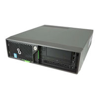
Server Front423
-
Server Rear424
-
Server Interior425
-
Onboard Settings429
