beautypg.com
Manuals
Brands
Fujitsu Manuals
Server
PRIMERGY TX150 S8
Fujitsu PRIMERGY TX150 S8 Manuals
Manuals and User Guides for Fujitsu PRIMERGY TX150 S8. We have
3
Fujitsu PRIMERGY TX150 S8 manuals available for free PDF download: Upgrade And Maintenance Manual, System Configurator And Order-Information Manual, Datasheet
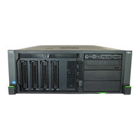
Fujitsu PRIMERGY TX150 S8 Upgrade And Maintenance Manual (430 pages)
Brand:
Fujitsu
| Category:
Server
| Size: 17.07 MB
Table of Contents
Table of Contents
7
Introduction
23
Notational Conventions
24
Before You Start
25
Classification of Procedures
27
Customer Replaceable Units (CRU)
27
Upgrade and Repair Units (URU)
28
Field Replaceable Units (FRU)
29
Average Task Duration
29
Tools You Need at Hand
30
Documents You Need at Hand
32
Important Information
35
Safety Instructions
35
CE Conformity
43
FCC Class a Compliance Statement
43
Environmental Protection
44
Basic Hardware Procedures
47
Using Diagnostics Information
47
Locating the Defective Server
47
Determining the Error Class
48
Global Error Indicator
48
Customer Self Service (CSS) Indicator
48
Locating the Defective Component
49
Local Diagnostic Indicators on the Front
49
Local Diagnostic Indicators on the System Board
49
Shutting down the Server
50
Disconnecting the Server from the Mains
50
Getting Access to the Component
51
Rack Model
51
Extending the Server out of the Rack
51
Removing the Server from the Rack
53
Removing the Top Cover
55
Removing the Rack Front Cover
56
Tower Model
58
Unlocking the Server
58
Removing the Side Cover
59
Removing Accessible Drive and HDD Bay Covers
60
Removing the Front Cover
61
Removing the System Air Duct
63
Reassembling
64
Installing the System Air Duct
64
Rack Model
65
Installing the Rack Front Cover
65
Installing the Top Cover
66
Mounting the Server in the Rack
67
Sliding the Server into the Rack
69
Tower Model
70
Installing the Front Cover
70
Installing Accessible Drive and HDD Bay Covers
71
Installing the Side Cover
72
Locking the Server
73
Connecting the Server to the Mains
74
Switching on the Server
75
Handling the System Fan Holder
76
Handling the Anti-Tilt Bracket
77
Handling Rubber Feet
78
Basic Software Procedures
79
Starting the Maintenance Task
79
Disabling or Suspending Bitlocker Functionality
79
Disabling SVOM Boot Watchdog Functionality
80
Viewing Boot Watchdog Settings
80
Configuring Boot Watchdog Settings
81
Removing Backup and Optical Disk Media
82
Verifying and Configuring the Backup Software Solution
83
Note on Server Maintenance in a Multipath I/O Environment
83
Switching on the ID Indicator
86
Completing the Maintenance Task
87
Updating or Recovering the System Board BIOS and Irmc
87
Updating or Recovering the System Board BIOS
87
Updating or Recovering the Irmc
87
Verifying System Information Backup / Restore
89
Updating RAID Controller Firmware
90
Enabling Option ROM Scan
91
Verifying and Configuring the Backup Software Solution
92
Resetting the Boot Retry Counter
93
Viewing the Boot Retry Counter
93
Enabling SVOM Boot Watchdog Functionality
94
Enabling Replaced Components in the System BIOS
95
Verifying the Memory Mode
96
Verifying the System Time Settings
96
Viewing and Clearing the System Event Log (SEL)
97
Viewing the SEL
97
Clearing the SEL
98
Updating the NIC Configuration File in a Linux Environment
99
Enabling Bitlocker Functionality
100
Performing a RAID Array Rebuild
101
Looking up Changed MAC / WWN Addresses
101
Looking up MAC Addresses
102
Looking up WWN Addresses
102
Using the Chassis ID Prom Tool
103
Configuring LAN Teaming
104
After Replacing / Upgrading LAN Controllers
104
After Replacing the System Board
104
Switching off the ID Indicator
105
Specifying the Chassis Model
105
Performing a Fan Test after Replacing a Defective Fan
106
Power Supply Units
109
Basic Information
110
Power Supply Unit Configurations
110
Assembly Rules
111
Standard Power Supply
112
Basic Information
112
Replacing the Standard Power Supply Unit
112
Preliminary Steps
112
Disconnecting Power Cables
113
Removing the Defective Standard Power Supply Unit
114
Installing the New Standard Power Supply Unit
116
Connecting Power Cables
119
Concluding Steps
119
Redundant Power Supply
120
Installing Hot-Plug Power Supply Units
120
Preliminary Steps
120
Removing the PSU Dummy Cover
120
Installing a Hot-Plug PSU
121
Concluding Steps
121
Removing a Hot-Plug PSU
122
Preliminary Steps
122
Removing a Hot-Plug PSU
123
Installing a PSU Dummy Cover
124
Replacing a Hot-Plug PSU
125
Preliminary Steps
125
Removing the Defective Hot-Plug PSU
125
Installing the New Hot-Plug PSU
126
Concluding Steps
126
Replacing the Power Backplane
126
Preliminary Steps
126
Removing the Hot-Plug Psus
126
Replacing the Defective Power Backplane
127
Concluding Steps
128
Converting a Standard Power Supply to a Redundant Power Supply
129
Preliminary Steps
129
Removing the Standard Power Supply Unit
129
Installing the Hot-Plug Power Supply Units
130
Concluding Steps
135
Hard Disk Drives / Solid State Drives
137
Basic Information
138
Inch HDD / SSD Configurations
138
8X 2.5-Inch HDD / SSD Configuration
138
Mounting Order
138
HDD / SSD Naming Scheme
139
16X 2.5-Inch HDD / SSD Configuration
140
Mounting Order
140
HDD / SSD Naming Scheme
141
Installing 2.5-Inch HDD / SSD Modules
142
Preliminary Steps
142
Removing a 2.5-Inch HDD / SSD Dummy Module
142
Installing a 2.5-Inch HDD / SSD Module
143
Concluding Steps
144
Removing 2.5-Inch HDD / SSD Modules
145
Preliminary Steps
145
Removing a 2.5-Inch HDD / SSD Module
146
Installing a 2.5-Inch HDD / SSD Dummy Module
147
Concluding Steps
147
Replacing a 2.5-Inch HDD / SSD Module
148
Preliminary Steps
148
Removing a 2.5-Inch HDD / SSD Module
149
Installing a 2.5-Inch HDD / SSD Module
149
Concluding Steps
149
Replacing a 2.5-Inch HDD SAS Backplane
149
Preliminary Steps
149
Removing the Defective SAS Backplane
150
Installing the New SAS Backplane
151
Concluding Steps
151
Inch HDD Configurations
152
4X 3.5-Inch HDD Configuration
152
Mounting Order
152
HDD / SSD Naming Scheme
152
6X 3.5-Inch HDD Configuration
153
Mounting Order
153
HDD / SSD Naming Scheme
154
8X 3.5-Inch HDD Configuration
154
Mounting Order
154
HDD / SSD Naming Scheme
155
Installing 3.5-Inch HDD Modules
156
Preliminary Steps
156
Removing a 3.5-Inch HDD Dummy Module
156
Installing a 3.5-Inch HDD Module
157
Concluding Steps
158
Removing 3.5-Inch HDD Modules
159
Preliminary Steps
159
Removing a 3.5-Inch HDD Module
160
Installing a 3.5-Inch HDD Dummy Module
161
Concluding Steps
161
Replacing a 3.5-Inch HDD Module
162
Preliminary Steps
162
Removing a 3.5-Inch HDD Module
163
Installing a 3.5-Inch HDD Module
163
Concluding Steps
163
Replacing a 3.5-Inch HDD SAS Backplane
163
Preliminary Steps
163
Removing the Defective 3.5-Inch HDD SAS Backplane
164
Installing the New 3.5-Inch HDD SAS Backplane
166
Concluding Steps
168
HDD Extension Boxes
169
HDD Extension Box Variants
169
Installing an HDD Extension Box
172
Preliminary Steps
172
Removing Accessible Drive Dummy Covers
173
Installing the HDD Extension Box
175
Concluding Steps
178
Removing an HDD Extension Box
179
Preliminary Steps
179
Removing the HDD Extension Box
179
Installing Accessible Drive Dummy Covers
181
Concluding Steps
182
Replacing an HDD Extension Box
183
Preliminary Steps
183
Removing the Defective HDD Extension Box
183
Installing the New HDD Extension Box
183
Concluding Steps
183
Fans
185
Basic Information
185
System Fans
188
Replacing the System Fans
188
Preliminary Steps
188
Removing the Defectice System Fans
188
Installing the New System Fans
188
Concluding Steps
188
Rear Fan
189
Installing the Rear Fan
189
Preliminary Steps
189
Concluding Steps
192
Removing the Rear Fan
193
Preliminary Steps
193
Concluding Steps
194
Replacing the Rear Fan
195
Preliminary Steps
195
Removing the Defectice Rear Fan
195
Installing the New Rear Fan
195
Concluding Steps
195
Expansion Cards and Backup Units
197
Basic Information
198
Handling Slot Brackets
200
Installing a Slot Bracket
200
Removing a Slot Bracket
204
Handling SFP+ Transceiver Modules
205
Installing SFP+ Transceiver Modules
205
Removing an SFP+ Transceiver Module
208
Expansion Cards in PCI Slots
211
Installing Expansion Cards
211
Preliminary Steps
211
Removing the PCI Slot Bracket
212
Installing an Expansion Card
212
Concluding Steps
215
Removing Expansion Cards
215
Preliminary Steps
215
Removing an Expansion Card
216
Installing a PCI Slot Bracket
218
Concluding Steps
218
Replacing Expansion Cards
219
Preliminary Steps
219
Removing an Expansion Card
219
Installing an Expansion Card
220
Connecting Cables to the Expansion Card
220
Connecting a Backup Unit to the Expansion Card
220
Concluding Steps
220
Replacing TFM
221
Preliminary Steps
221
Removing the Defective TFM
222
Installing the New TFM
222
Concluding Steps
222
Backup Units
223
Basic Information
223
Installing a BBU
224
Preliminary Steps
224
Connecting the BBU Cable to the BBU
224
Installing the BBU in the Holder
225
Installing the BBU with the Holder
226
Concluding Steps
228
Installing an FBU
229
Preliminary Steps
229
Installing TFM to the RAID Controller (if Applicable)
229
Installing the FBU in the Holder
230
Connecting the FBU Cable to the FBU
231
Installing the FBU with the Holder
232
Concluding Steps
233
Removing a BBU
233
Preliminary Steps
234
Removing the BBU with the Holder
234
Removing the BBU from the Holder
235
Disconnecting the BBU Cable from the BBU
235
Concluding Steps
236
Removing an FBU
236
Preliminary Steps
236
Removing the FBU with the Holder
237
Disconnecting the FBU Cable from the FBU
238
Removing the FBU from the Holder
238
Concluding Steps
239
Replacing a BBU
239
Preliminary Steps
239
Removing the Defective BBU
240
Installing the New BBU
240
Concluding Steps
240
Replacing an FBU
241
Preliminary Steps
241
Removing the Defective FBU
241
Installing the New FBU
242
Concluding Steps
242
Main Memory
243
Basic Information
244
Memory Sequence
245
Population Rules
245
Independant Channel Mode
246
Mirrored Channel Mode
246
Performance Mode
247
Rank Sparing Mode
247
Installing Memory Modules
248
Preliminary Steps
248
Installing a Memory Module
249
Concluding Steps
249
Removing Memory Modules
250
Preliminary Steps
250
Removing a Memory Module
250
Concluding Steps
251
Replacing Memory Modules
251
Preliminary Steps
251
Removing the Defective Memory Module
252
Installing the New Memory Module
252
Concluding Steps
252
Processors
253
Basic Information
254
Supported Processors
254
Processor Locations
254
Installing Processors
255
Preliminary Steps
255
Installing a Processor
255
Removing the Protective Cover
256
Installing the New Processor
257
Concluding Steps
259
Removing Processors
260
Preliminary Steps
260
Removing a Processor
260
Installing the Protective Cover
263
Concluding Steps
264
Upgrading or Replacing Processors
265
Preliminary Steps
265
Upgrading or Replacing a Processor
265
Concluding Steps
266
Handling Processor Heat Sinks
267
Preliminary Steps
267
Installing Processor Heat Sinks
268
Preparing the Heat Sink and Processor
268
Installing the Heat Sink
269
Removing Processor Heat Sinks
270
Replacing Processor Heat Sinks
271
Removing the Processor Heat Sink
271
Applying Thermal Paste
271
Installing the Processor Heat Sink
271
Concluding Steps
271
Applying Thermal Paste
272
Accessible Drives and LSD
275
Basic Information
276
Installing Accessible Drives
279
Preliminary Steps
279
Removing Accessible Drive Dummy Covers
279
Installing an Accessible Drive
282
Concluding Steps
285
Removing Accessible Drives
285
Preliminary Steps
285
Removing an Accessible Drive
286
Installing Accessible Drive Dummy Covers
286
Concluding Steps
287
Replacing Accessible Drives
287
Preliminary Steps
287
Removing the Defective Accessible Drive
288
Installing the New Accessible Drive
288
Concluding Steps
288
Slimline ODD and LSD in Multibay Box
289
Installing the Slimline ODD or LSD
289
Preliminary Steps
289
Installing the Slimline ODD
289
Installing the LSD Module
292
Removing Accessible Drive Dummy Covers
293
Installing the Multibay Box
293
Concluding Steps
295
Removing a Slimline ODD or LSD
296
Preliminary Steps
296
Removing the Multibay Box
296
Removing the Slimline ODD
297
Removing the LSD Module
299
Installing the Multibay Box
300
Concluding Steps
300
Replacing a Slimline ODD or LSD
301
Preliminary Steps
301
Removing the Defective Slimline ODD
301
Removing the Defective LSD Module
301
Installing the New Slimline ODD
301
Installing the New LSD Module
302
Concluding Steps
302
Slimline ODD and LSD in 2X 3.5-Inch HDD Extension Box
302
Installing the Slimline ODD or LSD
302
Preliminary Steps
302
Installing the Slimline ODD
303
Installing the LSD
306
Installing the 2X 3.5-Inch HDD Extension Box
307
Cabling the Slimline ODD and LSD
307
Concluding Steps
308
Removing the Slimline ODD or LSD
309
Preliminary Steps
309
Removing the Slimline ODD
310
Removing the LSD
312
Concluding Steps
314
Replacing the Slimline ODD or LSD
314
Preliminary Steps
314
Removing the Defective Slimline ODD
314
Removing the Defective LSD Module
315
Installing the New Slimline ODD
315
Installing the New LSD Module
315
Concluding Steps
315
Slimline ODD in 4X 3.5-Inch HDD Extension Box
316
Installing the Slimline ODD
316
Preliminary Steps
316
Installing the Slimline ODD
317
Installing the 4X 3.5-Inch HDD Extension Box
321
Cabling the Slimline ODD
321
Concluding Steps
321
Removing the Slimline ODD
322
Preliminary Steps
322
Removing the Slimline ODD
323
Concluding Steps
325
Replacing the Slimline ODD
325
Preliminary Steps
325
Removing the Defective Slimline ODD
326
Installing the New Slimline ODD
326
Concluding Steps
326
Front Panel and External Connectors
327
Front Panel Module
328
Replacing the Front Panel Module
328
Preliminary Steps
328
Removing the Front Panel Module
329
Replacing the Front Panel Module Cover
334
Installing the Front Panel Module
336
Concluding Steps
339
Front LAN Connector
340
Installing the Front LAN Connector
340
Preliminary Steps
340
Concluding Steps
343
Using the Front Management LAN Connector
343
Removing the Front LAN Connector
344
Preliminary Steps
344
Concluding Steps
345
Replacing the Front LAN Connector and Board
346
Preliminary Steps
346
Concluding Steps
346
System Board and Components
349
Basic Information
349
Replacing the CMOS Battery
350
Preliminary Steps
350
Removing the CMOS Battery
351
Installing the CMOS Battery
352
Concluding Steps
352
USB Flash Module (UFM)
353
Installing the UFM
353
Preliminary Steps
353
Installing the UFM
354
Concluding Steps
355
Software Configuration
355
Removing the UFM
356
Preliminary Steps
356
Concluding Steps
357
Replacing the UFM
357
Preliminary Steps
357
Removing the Defective UFM
358
Installing the New UFM
358
Concluding Steps
360
Software Configuration
360
Trusted Platform Module (TPM)
361
Installing the TPM
361
Preliminary Steps
361
Installing the TPM
362
Concluding Steps
365
Removing the TPM
365
Preliminary Steps
366
Removing the TPM
367
Concluding Steps
369
Replacing the TPM
369
Preliminary Steps
370
Removing the Defective TPM
370
Installing the New TPM
370
Concluding Steps
370
SCU (SKU) Key
371
Installing the SCU (SKU) Key
371
Preliminary Steps
371
Concluding Steps
372
Removing the SCU (SKU) Key
373
Preliminary Steps
373
Concluding Steps
374
Replacing the SCU (SKU) Key
374
Preliminary Steps
374
Replacing the System Board
375
Preliminary Steps
377
Removing the Defective System Board
377
Installing the New System Board
381
Concluding Steps
386
Converting a Tower Model to a Rack Model
389
Preliminary Steps
389
Converting a Tower Model to a Rack Model
390
Concluding Steps
402
Cabling
403
List of Used Cables
403
Cabling Plans
405
Replacing the Intrusion Switch Cable
409
Preliminary Steps
409
Removing the Defective Intrusion Switch Cable
410
Installing the New Intrusion Switch Cable
412
Concluding Steps
414
Appendix
415
Mechanical Overview
415
Server Front
415
Server Rear
417
Server Interior
418
Connectors and Indicators
419
Connectors and Indicators on the System Board
419
Onboard Connectors
419
Onboard Indicators and Controls
421
I/O Panel Connectors
423
I/O Panel Indicators
424
PSU Indicator (Only Hot-Plug Psus)
425
Connectors and Indicators on the Front Panel
426
Front Panel Connectors
426
Front Panel Controls and Indicators
426
Onboard Settings
428
Minimum Startup Configuration
429
Fujitsu PRIMERGY TX150 S8 System Configurator And Order-Information Manual (24 pages)
Brand:
Fujitsu
| Category:
Server
| Size: 0.73 MB
Table of Contents
Table of Contents
1
Processor
3
Memory
3
Accessible Drives
3
Hard Disk Drives
3
Communication/Network
3
Miscellaneous
3
Country Specific Power Cord
8
Independent Channel Mode
12
Mirrored Channel Mode
12
Performance Channel Mode
12
Rank Sparing Mode
12
Change Report
24
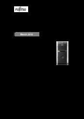
Fujitsu PRIMERGY TX150 S8 Datasheet (10 pages)
Mono-Socket Intel Xeon processor server
Brand:
Fujitsu
| Category:
Server
| Size: 0.16 MB
Table of Contents
Features and Benefits
2
Technical Details
3
Main Board
3
Operating Environment
6
Communication, Network
9
Warranty
9
More Information
10
Related Products
Fujitsu PRIMERGY TX150 S4
Fujitsu PRIMERGY TX150 S3
Fujitsu PRIMERGY TX150 S2
Fujitsu PRIMERGY TX150 S7
Fujitsu primergy TX150
Fujitsu PRIMERGY TX150 S6
Fujitsu PRIMERGY TX150 S5
Fujitsu PRIMERGY TX140 S2
Fujitsu PRIMERGY TX1320 M2
Fujitsu PRIMERGY TX1320 M3
Fujitsu Categories
Air Conditioner
Laptop
Server
Scanner
Storage
More Fujitsu Manuals