beautypg.com
Manuals
Brands
Fujitsu Manuals
Server
PRIMERGY RX4770 M6
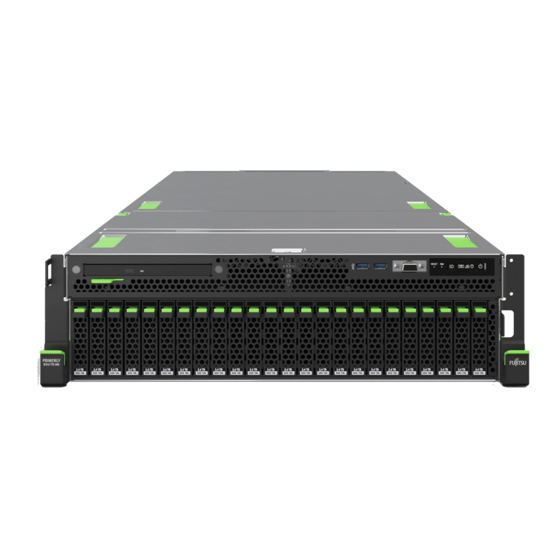
Fujitsu PRIMERGY RX4770 M6 Manuals
Manuals and User Guides for Fujitsu PRIMERGY RX4770 M6. We have
1
Fujitsu PRIMERGY RX4770 M6 manual available for free PDF download: Upgrade And Maintenance Manual
Fujitsu PRIMERGY RX4770 M6 Upgrade And Maintenance Manual (468 pages)
Brand:
Fujitsu
| Category:
Server
| Size: 8.34 MB
Table of Contents
Table of Contents
7
1 Introduction
17
Concept and Target Groups of this Manual
17
Notational Conventions
17
2 Before You Start
19
Basic Information
19
Proceeding
19
Advanced Thermal Design (ATD)
19
Installing Optional Components
20
Replacing a Defective Component
20
Classification of Procedures
21
Assignment of Unit Categories
21
Customer Replaceable Units (CRU)
21
Upgrade and Repair Units (URU)
22
Field Replaceable Units (FRU)
23
Average Task Duration
24
Tools You Need at Hand
25
Documentation Overview
26
Downloading Manuals
26
List of Documents
26
3 Important Information
29
Introduction
29
Safety Instructions
29
Basic Safety Instructions
29
Before Starting up
30
Installation and Operation
30
Batteries
33
Working with Optical Disk Drives (Odds) and Media
33
Laser Information
35
Modules with Electrostatic-Sensitive Devices (ESD Modules)
35
Transporting the Server
37
Installing the Server in the Rack
38
Other Important Information
38
Energy Star
39
CE Conformity
39
FCC Class a Compliance Statement
40
Environmental Protection
41
Basic Hardware Procedures
43
Determining the Error Class
43
Proceeding
43
Using Diagnostic Information
43
Locating the Defective Component
44
Removing the Front Cover with Lock
45
Shutting down the Server
46
Disconnecting the Power Cord
47
Disconnecting the Power Cord (AC PSU)
47
Getting Access to the Component
48
Extending the Server out of the Rack
48
Safety Notes
48
Removing the Server from the Rack
50
Removing the Top Covers
51
Reassembling
53
Installing the Top Covers
53
Safety Notes
53
Installing the Server in the Rack
55
Sliding the Server into the Rack
58
Connecting the Power Cord
59
Connecting the Power Cord (AC PSU)
59
Switching on the Server
60
Installing the Front Cover with Lock
61
Handling Riser Modules
62
Positions of Riser Modules
62
Installing a Riser Module
63
Removing a Riser Module
63
Handling the Fan Cage
64
Removing the Fan Cage
64
Installing the Fan Cage
66
Handling the Air Duct
68
Removing the Air Duct
68
Installing the Air Duct
71
Handling the Top System Board Carrier
73
Removing the Top System Board Carrier
73
Installing the Top System Board Carrier
76
5 Basic Software Procedures
81
Validation
81
Starting the Maintenance Task
81
Suspending Bitlocker Functionality
81
Disabling the Boot Watchdog
82
Removing Backup and Optical Disk Media
84
Verifying and Configuring the Backup Software Solution
84
Switching on the ID Indicator
84
Completing the Maintenance Task
85
Updating or Recovering the BIOS and Irmc S5
85
Verifying System Information Backup or Restore
88
Updating Expansion Card Firmware
89
Reconfiguring the Backup Software Solution
91
Resetting the Boot Retry Counter
91
Resetting the Error Status after Replacing Memory Modules or CPU
93
Resetting the Error Status after Replacing Cpus
93
Resetting the Error Status after Replacing Memory Modules
95
Locating the Defective Server
97
Enabling the Boot Watchdog
98
Enabling Replaced Components in the BIOS
99
Verifying the Memory Mode
99
Verifying the System Time Settings
100
Viewing and Clearing the System Event Log (SEL)
101
Updating the NIC Configuration File in a Linux and Vmware Environment
104
Resuming Bitlocker Functionality
104
Performing a RAID Array Rebuild
105
Looking for MAC/WWN/GUID and SAS Addresses
106
Basic Information
106
Looking for the MAC Address of a LAN Controller
107
Looking for the WWN Address of a Fibre Channel Controller
108
Looking for the GUID Address of an Infiniband or Omni-Path Controller
109
Looking for SAS Addresses of SAS Controllers for External Devices
109
Using the Chassis ID Prom Tool
110
Configuring LAN Teaming
112
Switching off the ID Indicator
113
Performing a Fan Test
114
Updating the Golden Image
115
Updating the Golden Image for Irmc S5 Firmware
115
Updating the Golden Image for BIOS Firmware
117
Power Supply Unit (PSU)
119
Safety Notes
119
Installing a Hot-Plug PSU
123
Redundant Power Supply
123
Removing a Hot-Plug PSU
125
Replacing a Hot-Plug PSU
128
Replacing the Power Distribution Board
129
Basic Information
119
7 Hard Disk Drive (HDD) / Solid State Disk (SSD)
135
Safety Notes
135
Basic Information
136
Handling Hdds or Ssds Without Installation Frame
137
Inch HDD/SSD and 2.5-Inch Installation Frame
137
2.5-Inch HDD/SSD Configurations
139
Overview of Configurations
139
Configuration with up to Eight HDD/SSD or Pcie SSD Modules
139
Configuration with up to 16 HDD/SSD or Pcie SSD Modules
140
Configuration with up to 24 HDD/SSD or Pcie SSD Modules
141
Installing 2.5-Inch HDD/SSD Modules
142
Removing 2.5-Inch HDD/SSD Modules
145
Replacing a 2.5-Inch HDD/SSD Module
147
Replacing a 8X 2.5-Inch HDD Backplane
149
Switch Board
155
Upgrading Configuration from Eight to 16 2.5-Inch Hdds/Ssds
159
Replacing the SAS Expander Board
162
8 Fans
167
Safety Notes
167
Basic Information
167
Replacing a Fan Module
168
Expansion Cards and Backup Units
171
Safety Notes
171
Basic Information
172
Handling Slot Brackets
175
Installing Slot Brackets
175
Installing SFP+ Transceiver Modules
177
Removing Slot Brackets
177
Handling SFP+ Transceiver Modules
177
Removing SFP+ Transceiver Modules
183
OCP (Open Compute Project) Modules
187
Position of the OCP Module
187
Installing an OCP Module
188
Removing an OCP Module
190
Replacing the OCP Module
192
Expansion Cards in Standard Pcie Slots
194
Installing an Expansion Card
194
Removing an Expansion Card
200
Replacing an Expansion Card
203
Replacing a Pcie Holder
205
Expansion Cards in Riser Modules
208
Installing an Expansion Card in a Riser Module
208
Removing an Expansion Card from a Riser Module
210
Replacing an Expansion Card from a Riser Module
212
GPU Cards in Riser Modules
214
Installing a GPU Card in a Riser Module
214
Removing a GPU Card from a Riser Module
222
Replacing a GPU Card from a Riser Module
223
Replacing a Riser Card
225
Flash Backup Unit (FBU)
227
Installing an FBU
227
Position of the Fbus
227
Removing an FBU
231
Replacing an FBU
233
10 Main Memory
235
Safety Notes
235
Basic Information
236
Slots and Features
236
Memory Population Conditions
239
Modes of Operation
240
Ddr4 DIMM
240
DDR4 DIMM and Optane Pmem Modules
241
Installing Memory Modules
243
Removing Memory Modules
247
Replacing Memory Modules
250
Handling Memory Dummy Modules
253
11 Processor (CPU)
255
Safety Notes
255
Basic Information
256
Upgrading to 4 CPU Configuration
258
Replacing a CPU or Heat Sink
269
12 Liquid Cooling (LC)
277
Safety Notes
277
Basic Information
277
Replacing the CPU or LC Kit
281
Accessible Drives
299
Safety Notes
299
Basic Information
299
Optical Disk Drive (ODD)
300
Positions of the ODD
300
Installing the ODD
302
ODD Latch
302
Removing the ODD
307
Replacing the ODD
312
Front Panel
315
Safety Notes
315
Basic Information
315
Common Operation Panel (COP)
316
Replacing the COP
316
Front VGA
323
Replacing the Front VGA
323
System Board and Components
327
Safety Notes
327
Basic Information
327
CMOS Battery
328
Replacing the CMOS Battery
328
Trusted Platform Module (TPM)
331
TPM Kit
331
Installing the TPM
332
Position of the TPM
332
Removing the TPM
336
Replacing the TPM
341
Installing the Irmc Microsd Card
345
Irmc Microsd Card
345
Note for Embedded Lifecycle Management (Elcm)
345
Removing the Irmc Microsd Card
347
Replacing the Irmc Microsd Card
349
M.2 Ssd
350
Slots and Bolts for M.2 Ssds
350
Installing an M.2 SSD
352
Removing an M.2 SSD
356
Replacing an M.2 SSD
359
Dual Microsd 64GB Enterprise
361
Installing the Dual Microsd 64GB Enterprise
361
Position of the Dual Microsd 64GB Enterprise
361
Removing the Dual Microsd 64GB Enterprise
365
Replacing the Dual Microsd 64GB Enterprise
367
Replacing the Microsd Card
369
Replacing the UPI Cables
371
UPI Cables
371
Replacing the Top System Board
373
System Board
373
Replacing the Bottom System Board
378
16 Appendix A
387
16 Appendix A Mechanical Overview
387
Inch HDD/SSD Configuration
387
Server Front
387
Server Rear
389
Server Rear with Air Cooling
389
Server Rear with Liquid Cooling
390
Server Interior
391
Servers with Air Cooling
391
Servers with Liquid Cooling (LC)
393
Connectors and Indicators
395
System Board
395
Bottom System Board D3892-A100
395
Top System Board D3892-B100
400
Connectors on the Server Front
403
Server Front
403
Indicators on the COP
404
Indicator on the ODD
407
Indicators on Hot-Plug HDD / SSD / Pcie SSD Modules
408
Connectors on the Server Rear
409
Server Rear
409
ID, CSS and Global Error Indicators
410
LAN Indicators
413
Indicator of the Hot-Plug System Fan
414
Indicator on Hot-Plug PSU
414
Acoustic Indicators
415
Onboard Settings
416
Minimum Startup Configuration
417
17 Appendix B
419
Supplied Documents
419
Related Products
Fujitsu Primergy RX4770 M1
Fujitsu PRIMERGY RX4770 M2
Fujitsu PRIMERGY RX4770 M4
Fujitsu PRIMERGY RX4770 M5
Fujitsu PRIMERGY RX200 S5
Fujitsu PRIMERGY RX800 S2
Fujitsu PRIMERGY RX330 S1
Fujitsu Primergy RX100 S4
Fujitsu PRIMERGY RX100 S6
Fujitsu PRIMERGY RX1330 M4
Fujitsu Categories
Air Conditioner
Laptop
Server
Scanner
Storage
More Fujitsu Manuals