beautypg.com
Manuals
Brands
Fujitsu Manuals
Server
Primergy BX900 S2
Fujitsu Primergy BX900 S2 Manuals
Manuals and User Guides for Fujitsu Primergy BX900 S2. We have
2
Fujitsu Primergy BX900 S2 manuals available for free PDF download: Upgrade And Maintenance Manual, Operating Manual
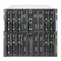
Fujitsu Primergy BX900 S2 Upgrade And Maintenance Manual (206 pages)
System Unit
Brand:
Fujitsu
| Category:
Server
| Size: 8.16 MB
Table of Contents
System Unit
1
Copyright and Trademarks
2
Table of Contents
7
Version History
15
1 Introduction
17
Where to Find Which Information
18
Notational Conventions
19
2 Before You Start
21
Classification of Procedures
22
Customer Replaceable Units (CRU)
22
Upgrade and Repair Units (URU)
23
Field Replaceable Units (FRU)
24
Average Task Duration
24
Tools You Need at Hand
25
Documents You Need at Hand
27
3 Important Information
29
Safety Instructions
29
CE Conformity
38
FCC Class a Compliance Statement
39
Environmental Protection
40
4 Basic Hardware Procedures
43
Using Diagnostics Information
43
Accessing the Management Blade Web Interface
44
Locating the Defective System Unit
45
Determining the Error Class
45
Global Error Indicator
47
Customer Self Service (CSS) Indicator
47
Locating the Defective Component
48
Opening the Rack Door
48
Shutting down the System Unit
49
Connecting the System Unit to the Mains
50
Switching on the System Unit
52
Removing / Installing Server Blades and Storage Blades
54
Installing a Single Height / Single Width Blade
55
Installing a Single Height / Double Width Blade
57
Installing a Dummy Server Blade Module
59
Concluding Software Tasks
60
Closing the Rack Door
60
5 Basic Software Procedures
63
Starting the Maintenance Task
63
Switching on the ID Indicator
63
Saving / Restoring Management Blade Settings
64
Completing the Maintenance Task
66
Updating / Recovering the Management Blade Firmware
66
Looking up the Management Blade Firmware Version
66
Updating the Management Blade Firmware Via Management Blade Web Interface
67
Updating the Management Blade Firmware Via Recovery Flash
68
Verifying the Management Blade Time Settings
70
Viewing and Clearing the System Event Log (SEL)
71
Viewing the SEL
71
Clearing the SEL
72
Checking Management Master/Slave Behavior
73
Updating the Connection Blade Firmware
74
Configuring Connection Blade Settings
75
Saving Connection Blade Settings
76
Restoring Connection Blade Settings
78
Verifying Power Consumption
80
Configuring Power Supply Redundancy
81
Using the Chassis ID Prom Tool
82
Switching off the ID Indicator
83
6 Power Supply
85
Basic Information
86
Power Supply Redundancy
86
Cooling Requirements
88
Installing a Power Supply Unit
93
Required Tools
93
Preliminary Steps
93
Installing a Power Supply Unit
94
Concluding Steps
94
Replacing a Power Supply Unit
95
Required Tools
95
Preliminary Steps
95
Removing the Power Supply Unit
96
Concluding Steps
97
7 Fan Module and Fan Unit
99
Replacing a Fan Module
99
Required Tools
99
Preliminary Steps
99
Removing the Fan Module
100
Installing the Fan Module
100
Concluding Steps
100
Replacing a Fan Unit
101
Required Tools
101
Preliminary Steps
102
Removing the Fan Unit
102
Installing the Fan Unit
103
Concluding Steps
103
8 Connection Blades
105
Basic Information
105
Connection Blade Fitting Rules
106
Port Assignment
109
Port Assignment of Switch Connection Blades
110
Port Assignment of Connection Blade 8Gb FC Pass Thru 18/18
111
Port Assignment of Connection Blade Ethernet Pass Thru 10Gb
111
Single-Width Connection Blades
112
Installing Single-Width Connection Blades
112
Required Tools
112
Preliminary Steps
112
Removing Connection Blade Dummy Module
113
Installing a Single-Width Connection Blade
113
Concluding Steps
115
Removing Single-Width Connection Blades
115
Required Tools
115
Preliminary Steps
115
Removing a Single-Width Connection Blade
116
Installing a Connection Blade Dummy Module
117
Concluding Steps
117
Replacing Single-Width Connection Blades
117
Required Tools
117
Preliminary Steps
118
Removing a Connection Blade
118
Installing a Single-Width Connection Blade
118
Concluding Steps
118
Double-Width Connection Blades
119
Installing Double-Width Connection Blades
119
Required Tools
119
Preliminary Steps
119
Removing Connection Blade Dummy Modules
120
Installing a Double-Width Connection Blade (Infiniband)
120
Concluding Steps
122
Removing Double-Width Connection Blades
123
Required Tools
123
Preliminary Steps
123
Removing a Double-Width Connection Blade
124
Installing Connection Blade Dummy Modules
124
Concluding Steps
125
Replacing Double-Width Connection Blades
125
Required Tools
125
Preliminary Steps
125
Removing the Connection Blade
126
Installing a Double-Width Connection Blade
126
Concluding Steps
126
Additional Tasks
127
Handling SFP+ Transceiver Modules
127
Installing SFP+ Transceiver Modules
127
Removing an SFP+ Transceiver Module
133
Replacing SFP+ Transceiver Modules
136
Connection Blade Stacking
137
Further Information
142
9 Management Blades
143
Basic Information
143
Installing a Second Management Blade
144
Required Tools
144
Preliminary Steps
144
Removing the Management Blade Dummy Module
144
Installing the Management Blade
145
Concluding Steps
145
Replacing a Management Blade
146
Required Tools
146
Preliminary Steps
146
Removing the Defective Management Blade
147
Installing the Management Blade
147
Concluding Steps
147
Replacing the Management Blade Battery
148
Required Tools
148
Preliminary Steps
148
Concluding Steps
150
10 Local Service Display
151
Replacing the Local Service Display
151
Required Tools
151
Preliminary Steps
151
Removing the Local Service Display
152
Installing the Local Service Display
154
Concluding Steps
155
11 Front Docking Board
157
Basic Information
158
Replacing the Front Docking Board
160
Required Tools
160
Preliminary Steps
160
Removing the Front Docking Board
161
Installing the Front Docking Board
164
Concluding Steps
166
12 Midplane
167
Basic Information
167
Replacing the Midplane
169
Required Tools
169
Preliminary Steps
169
Removing the Rear Chassis
170
Removing the Midplane
172
Installing the Midplane
173
Installing the Rear Chassis
173
Concluding Steps
173
13 Appendix
175
Mechanical Overview
175
System Unit Front
175
System Unit Rear
176
System Unit Interior
177
Configuration Tables
178
Server Blade / Storage Blade Fitting Rules
178
Power Supply Unit / Fan Module Fitting Rules
178
Connection Blade Fitting Rules and Port Assignment
179
Connectors and Indicators
179
Front of System
179
Control Elements on the Local Service Display
180
Leds on the Control Panel
181
Back of System
183
Connectors on the Management Blade
183
Control Elements and Indicators on the Management Blade
184
Indicators on the Hot-Plug Power Supply Units
186
Indicators on the Fan Modules
187
Indicators and Connectors of the Connection Blades
188
Connection Blade Gbe Switch/Ibp 18/6 (SB6)
188
Connection Blade Gbe Switch/Ibp 36/12 (SB11A)
189
Connection Blade Gbe Switch/Ibp 36/8+2 (SB11)
191
Connection Blade 10 Gbe Switch/Ibp 18/8
193
Connection Blade Ethernet Pass Thru 10Gb 18/18
195
Connection Blade 8Gb FC Switch 18/8
196
Connection Blade 8Gb FC Pass Thru 18/18
197
Connection Blade DCB SW 10Gb 18/6+6
198
Connection Blade FEX B22F 10Gb (Cisco)
200
Connection Blade Infiniband Switch 40 Gb 18/18
201
Connection Blade Infiniband Switch 56 Gb 18/18 FDR
202
Connection Blade SAS Switch 6 Gb 18/6
203
Management Blade Settings
204
Minimum Startup Configuration
205
Fujitsu Primergy BX900 S2 Operating Manual (108 pages)
Blade Server
Brand:
Fujitsu
| Category:
Server
| Size: 4.36 MB
Table of Contents
Blade Server
1
Copyright and Trademarks
2
Table of Contents
5
1 Introduction
7
Concept and Target Groups for this Manual
7
Documentation Overview
8
Notational Conventions
10
2 Functional Overview
11
Features
11
System Unit Specification
29
3 Installation Steps, Overview
33
4 Important Information
35
Safety Instructions
35
CE Conformity
43
FCC Class a Compliance Statement
43
Environmental Protection
45
5 Hardware Installation
47
Unpacking the System Unit
48
Installing/Removing the System Unit
49
Installation in Primecenter/Datacenter Rack
51
Installing/Removing the System Unit
57
Connecting Devices to the System Unit
60
Cable Routing
61
Connecting the System Unit to the Mains
61
Using Cable Ties
64
Notes on Connecting/Disconnecting Cables
65
6 Starting up and Operation
67
Control and Display Elements
67
Front of System
67
Control Elements
70
Leds on the Control Panel
70
ID Card
72
Back of System
73
Control and Display Elements on the Management Blade
73
Indicators on the Hot-Plug Power Supply Units
76
Indicators on the Hot-Plug Fans
77
Indicators and Connectors of the Connection Blades
78
Connection Blade Gbe Switch/Ibp 18/6 (SB6)
78
Connection Blade Gbe Switch/Ibp 36/12 (SB11A)
79
Connection Blade Gbe Switch/Ibp 36/8+2 (SB11)
81
Connection Blade 10 Gbe Switch/Ibp 18/8
83
Connection Blade Ethernet Pass Thru 10Gb 18/18
85
Connection Blade 8Gb FC Switch 18/8
86
Connection Blade 8Gb FC Pass Thru 18/18
87
Connection Blade DCB SW 10Gb 18/6+6
88
Connection Blade FEX B22F 10Gb (Cisco)
90
Connection Blade Infiniband Switch 40 Gb 18/18
91
6.1.3.11 Connection Blade Infiniband Switch 56 Gb 18/18 FDR
92
Connection Blade SAS Switch 6 Gb 18/6
93
Switching the System Unit On/Off
94
Configuring Management Blades
96
Cleaning the System Unit
102
7 Property and Data Protection
103
8 Troubleshooting and Tips
105
System Power Indicator Does Not Light up
105
Front or Back Error LED Flashes Orange
106
System Switches Itself off
107
Related Products
Fujitsu PRIMERGY BX900 S1
Fujitsu PRIMERGY BX900
Fujitsu PRIMERGY BX960 S1
Fujitsu PRIMERGY BX924 S3
Fujitsu PRIMERGY BX922 S2
Fujitsu PRIMERGY BX924 S2
Fujitsu PRIMERGY BX920 S2
Fujitsu Primergy BX920 S3
Fujitsu Primergy BX920 S4
Fujitsu PRIMERGY BX924 S4
Fujitsu Categories
Air Conditioner
Laptop
Server
Scanner
Storage
More Fujitsu Manuals