beautypg.com
Manuals
Brands
Emerson Manuals
Transmitter
Rosemount5081
Emerson Rosemount5081 Manuals
Manuals and User Guides for Emerson Rosemount5081. We have
1
Emerson Rosemount5081 manual available for free PDF download: Instruction Manual
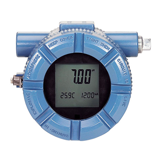
Emerson Rosemount5081 Instruction Manual (152 pages)
Explosion-Proof Transmitter
Brand:
Emerson
| Category:
Transmitter
| Size: 12.75 MB
Table of Contents
Table of Contents
5
Chapter 1 Startup Procedure
11
Chapter 2 Description and Specifications
13
Features and Applications
13
General Specifications
13
Hazardous Area Certifications
15
Functional Specifications
17
Ordering Information
20
Chapter 3 Installation
21
Unpacking and Inspection
21
Installation
21
General Information
21
Orienting the Display Board
22
Mounting on a Flat Surface
22
Mounting on a Pipe
22
Chapter 4 Wiring
25
Wiring Overview
25
Power Supply/Current Loop
25
Power Supply Overview
25
HART and Foundation Fieldbus
26
Chapter 5 Display and Operation
29
User Interface and Main Display
29
Infrared Remote Control (IRC)
30
Menu System
31
Overview of Main Menus
31
Chapter 6 Programming - Basics
43
5081 Programming
43
Ma Outputs and Current Generated During Hold and Faults
43
Temperature Correction
45
Set up Custom Curves (Conductivity Measurements Only)
46
Setting up a Custom Curve
46
Restore to Default Factory Settings
47
Configuration Overview
47
Returning to Factory Default Settings
47
Setting Access (Security) Code
48
Security Overview
48
Entering the Access (Security) Code
48
Retrieving a Lost Security Code
48
Using HOLD
48
HOLD Overview
48
Activating or Deactivating HOLD
49
Chapter 7 Measurements
51
Calibrating Ph Sensors
51
Calibration Overview
51
Calibration Standards (Buffer Solutions)
51
Auto-Calibration Procedure
51
Manual Calibration
53
Standardization for Ph
54
Standardization Overview
54
Standardization Procedure
54
Calibrating ORP Sensors
55
ORP Overview
55
Calibrating Temperature with an ORP Sensor
55
Standardization
56
Preparation of ORP Standard Solutions
56
Standardizing with an ORP Sensor
56
Matching Transmitter to ORP Sensor's Temperature Element
56
Calibrating Contacting and Toroidal Conductivity Sensors
56
Overview of Calibrating Contacting Conductivity Sensors
56
Calibrating with Contacting and Conductivity Sensors
56
Zeroing the Sensor
57
Adjusting the Temperature
57
In-Process Calibration
57
Temperature Slope
57
Output Calibration
58
Calibrating Dissolved Oxygen, Ozone, Free Chlorine, Total Chlorine, and Ozone Sensors
58
Calibrating Amperometric Sensors
58
Zeroing the Sensor Procedure
58
Air Calibration Procedure (Dissolved Oxygen)
59
In-Process Calibration Procedure (Dissolved Oxygen)
60
Full Scale Calibration Procedure (Free Chlorine, Total Chlorine, Ozone)
61
Dual Slope Calibration (Free Chlorine, Total Chlorine)
61
Chapter 8 Diagnostics and Troubleshooting
63
Ph/Orp Diagnostics and Troubleshooting
63
5081-P Warning and Fault Messages
63
Calibration Errors
64
Troubleshooting - General
64
Troubleshooting When a Diagnostic Message Is Showing
65
Glassfail
65
Glasswarn
68
Ref FAIL
69
Ref Warn
70
Calibrate
71
Temp HI and Temp lo
71
Line FAIL
73
Input Warn
74
SLOPE Err lo
75
SLOPE Err HI
76
Std Err
77
Rom FAIL or CPU FAIL
77
Adc Warn or Cycle Pwr
77
Write Err
77
Fact FAIL Error Message
78
Troubleshooting When no Diagnostic Message Is Showing
78
Id000 in Display
79
Transmitter Not Responding to IRC
79
SLOPE Err lo or SLOPE Err Hi Appear after Calibration Attempt
79
Bf1 or Bf2 Continuously Flashes During Auto Calibration
79
Ph Reading in Buffer Drifts During Manual Calibration
80
Buffer Calibration Is Acceptable; Process Ph Is Slightly Different from Expected Value
81
Buffer Calibration Is Acceptable; Process Ph Is Grossly Different from Expected Value
81
Temperature Reading Is Inaccurate
82
HART Communications Problems
82
No Display
83
Display Segments Missing
83
Transmitter Locks up
83
Transmitter Periodically Restarts Itself
83
Displaying Diagnostic Variables
84
Purpose
84
Testing the Transmitter by Simulating the Ph
85
Overview of Simulating a Ph Input
85
Ph Simulation When the Preamplifier Is Located in the Transmitter
85
Ph Simulation When the Preamplifer Is Located in a Remote Junction Box or in a Sensor-Mounted Junction Box
87
Ph Simulation with 381+ Sensor
88
Ph Simulation When Preamplifier Is in Sensor
91
Factory Assistance and Repairs
91
Troubleshooting Assistance
91
Contacting and Toroidal Conductivity Diagnostics and Troubleshooting
91
Overview of Diagnose Menu
91
Troubleshooting Contacting Conductivity Analyzers
91
Displaying Diagnostic Values
91
Fault Conditions
92
Disabling Faults
92
Non-Disabling Warnings
93
Diagnostic Messages
93
Quick Troubleshooting Guide
94
Field Troubleshooting
95
Systematic Troubleshooting
96
RTD Resistance Values
96
5081C Warning and Fault Messages
97
Troubleshooting Contacting and Toroidal Conductivity Analyzers When a Fault or Warning Message Is Showing
98
Ouer Range and AMP FAIL
98
Sensor FAIL
98
CAL Error
99
Need 0 CAL
99
Rtd FAIL, TEMP HI, and TEMP lo
99
Sense Open
100
Offset Err
100
Fact FAIL Procedure
101
CPU FAIL and ROM FAIL
102
Adc Error
102
5081-A Diagnostics
102
Diagnostics Overview
102
Diagnostic Messages for Dissolved Oxygen
102
Diagnostic Messages for Ozone and Total Chlorine
103
Diagnostic Messages for Free Chlorine
103
5081-A Troubleshooting
103
5081-A Warning and Fault Messages
103
Troubleshooting Fault or Warning Messages
104
Bad Sensor
105
Too Big
106
Bad Rtd, TEMP HI, TEMP LO, and Rtd Open
106
Ph in
106
SLOPE HI or SLOPE lo
107
0- Offset
107
Adc
108
Bad Gnd
108
In too Big
108
Rite Err
108
Temperature Measurement and Calibration Problems
109
Temperature Different from Transmitter
109
Oxygen Measurement and Calibration Problems
109
Zero Current too High
109
Zero Reading Unstable
110
Sensor Current Different from below
110
Process and Standard Readings Different
111
Process Readings Erratic
111
Readings Drift
112
Sensor Not Responding to Oxygen Changes
112
Oxygen Readings too Low
112
Free Chlorine Measurement and Calibration Problems
113
Zero Current Outside Range
113
Chlorine Zero Reading Unstable
113
Sensor Current too Low
114
Chlorine Process Readings Erratic
114
Chlorine Readings Drift
115
Sensor Not Responding to Chlorine Changes
115
Chlorine Readings Spike
115
Chlorine Readings too Low
116
Total Chlorine Measurement and Calibration Problems
116
Ozone Measurement and Calibration Problems
116
Ozone Zero Current Outside Range
116
Ozone Zero Reading Unstable
117
Sensor Current Less than 350 Na/Ppm
117
Ozone Process Readings Erratic
118
Ozone Readings Drift
118
Sensor Not Responding to Ozone Changes
118
Ozone Readings too Low
118
Ph Measurement and Calibration Problems
119
Ph SLOPE HI or SLOPE lo
119
Ph -0- Offset Message
119
Transmitter Not Accepting Manual Slope
119
Sensor Not Responding to Ph Changes
120
Process Ph Slightly Different
120
Process Ph Reading Changes with Flow
120
Process Ph Grossly Wrong or Noisy
120
Process Readings Noisy
121
Simulating Input Currents - Dissolved Oxygen
122
Simulating Input Currents - Chlorine and Ozone
123
Simulating Inputs - Ph
124
General Information about Simulating Ph Inputs
124
Preamplifier in Transmitter
124
Preamplifier in a Junction Box
126
Preamplifier in Sensor
126
Simulating Temperature
126
General Information about Simulating Temperature
126
Simulating Temperature Procedure
127
Measuring Reference Voltage
128
Chapter 9 Digital Communications
131
HART Communications
131
Overview of HART Communication
131
HART Interface Devices
131
Foundation Fieldbus Communication
132
Foundation Fieldbus Specifications
133
Asset Management Solutions
134
Chapter 10 Return of Material
137
General Information about Returning Material
137
Warranty Repair
137
Non-Warranty Repair
137
Appendix A Engineering Drawings
139
Appendix B EU Declarations of Conformity
147
Eu Declaration of Conformity
148
Related Products
Emerson Rosemount 520
Emerson Rosemount
Emerson Rosemount 3051 Series
Emerson Rosemount TCL
Emerson Rosemount Oxymitter 4000
Emerson Rosemount 2051 Wireless Series
Emerson Rosemount Ultrasonic 3108
Emerson Rosemount X-well 648
Emerson Rosemount 3108
Emerson Rosemount 702 Series
Emerson Categories
Controller
Control Unit
Transmitter
Measuring Instruments
Fan
More Emerson Manuals