beautypg.com
Manuals
Brands
Allen-Bradley Manuals
I/O Systems
1756-IRT8I
Allen-Bradley 1756-IRT8I Manuals
Manuals and User Guides for Allen-Bradley 1756-IRT8I. We have
2
Allen-Bradley 1756-IRT8I manuals available for free PDF download: User Manual, Reference Manual
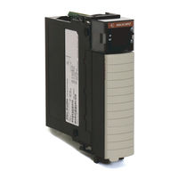
Allen-Bradley 1756-IRT8I User Manual (226 pages)
High Resolution Analog I/O Modules
Brand:
Allen-Bradley
| Category:
I/O Systems
| Size: 6.23 MB
Table of Contents
Table of Contents
3
Preface
9
Product Compatibility and Download Center
9
Summary of Changes
9
Additional Resources
10
Before You Begin
11
Chapter 1 Ownership
13
1756-OF8I Redundant Owner
13
Configure a Module
13
Direct Connections
14
Input Module Operation
15
Requested Packet Interval (RPI)
15
Input Modules in a Local Chassis
16
Input Modules in a Remote Chassis
17
Trigger Event Tasks
17
Output Module Operation
18
Output Modules in a Local Chassis
19
Output Modules in a Remote Chassis
19
Listen-Only Mode
20
Chapter 2 Common Analog I/O Features
22
CIP Sync Timestamp of Data
22
Rolling Timestamp of Data
23
Floating Point Data Format
23
Module Quality Reporting
24
Calibration
25
Fault and Status Reporting
25
Configurable Software
26
Latching of Alarms
26
Module Inhibiting
27
Electronic Keying
28
Elegant Migration Emulation Mode
29
Relationship between Module Resolution and Scaling
31
Module Resolution
31
Scaling
32
Calibration
33
Calibrated Accuracy
34
Error Calculated over Hardware Range
34
RTD and Thermocouple Error Calculations
34
RTD Error
35
Thermocouple Error
35
Module Error at 25 °C (77 °F)
36
Thermocouple Resolution
38
1756-IF8I Module Features
41
Analog I/O Module Features
22
Chapter 3
42
Internal Loop Power Source
42
Multiple Input Ranges
43
Notch Filter
43
Underrange/Overrange Detection
46
Digital Filter
47
Process Alarms
48
Rate Alarm
50
Sensor Offset
50
Wire off Detection
51
Synchronized Sampling
52
1756-IF8I Diagrams
53
Fault and Status Reporting
58
Common Module Features
59
Chapter 4
60
Module Input Ranges
60
Notch Filter
61
Underrange/Overrange Detection
65
Digital Filter
65
Process Alarms
66
Rate Alarm
68
Sensor Offset
68
10 Ohm Copper Offset
68
Wire off Detection
69
Temperature Units
71
Sensor Types
71
1756-IRT8I Thermocouple Wire Length Compensation
73
Synchronized Sampling
74
Cold Junction Compensation
75
1756-IRT8I Diagrams
79
1756-IR12 Diagrams
84
1756-IT16 Diagrams
86
Fault and Status Reporting
88
1756-OF8I Module Features
89
Rockwell Automation Publication 1756-UM540E-EN-P - December
89
Chapter 5
90
Multiple Output Ranges
90
Channel Offset
90
Ramping/Rate Limiting
90
Hold for Initialization
91
Clamping/Limiting
91
Clamp/Limit Alarms
92
Data Echo
92
1756-OF8I Diagrams
93
Drive Different Loads with the 1756-OF8I Module
96
Fault and Status Reporting
97
Redundant Owners
98
Configure 1756-OF8I Redundant Owners
98
About Redundant Owners
99
Configure the Output Module
103
Response Times for Output Modules
105
Input Modules
106
Troubleshooting
107
I/O Modules Key the Removable Terminal Block
109
Chapter 6
110
Install the I/O Module
111
Key the Removable Terminal Block
113
Connect Wiring
114
Connect the Grounded End of the Cable
115
Connect the Ungrounded End of the Cable
116
RTB Types
117
RTB Wiring Recommendations
118
Assemble the RTB and the Housing
119
Choose Extended-Depth Housing
120
Cabinet Size Considerations with Extended-Depth Housing
121
Install the Removable Terminal Block
122
Remove the Removable Terminal Block
123
Remove the Module from the Chassis
124
Chapter 7 Create a New Module
126
Module Definition
128
Edit the Configuration
129
Connection Tab
130
Configuration Tab
131
Calibration Tab
134
Alarm Configuration Tab
137
Limit Configuration Tab
139
Copy Channel Configuration
139
View the Module Tags
141
Difference between Calibrating an Input Module
144
Chapter 8 And an Output Module
144
Calibrate Via Profile or Ladder
145
Calibrate the Input Modules
145
Calibrate the 1756-IF8I Module Via the Profiles
145
Calibrate the Temperature-Sensing Modules
150
Calibrate the Output Module
158
For a Current Output Type
159
Status Indicators for the 1756-IF8I Module
165
Chapter 9
166
Status Indicators for the 1756-IRT8I Module
166
Status Indicators for the 1756-IR12 Module
166
Status Indicators for the 1756-IT16 Module
167
Status Indicators for the 1756-OF8I Module
167
Use Logix Designer Application for Troubleshooting
168
Fault Type Determination
169
Troubleshoot Incorrect Readings on the Module
170
Incorrect Temperature Readings
170
1756-IRT8I and 1756-IR12 Modules
170
Incorrect RTD Readings
173
Incorrect Input Voltage/Current Readings
175
Incorrect Output Voltage/Current Readings
178
Rockwell Automation Publication 1756-UM540E-EN-P - December
179
Appendix A
181
Access the Tags
181
1756-IF8I Module
183
1756-IF8I Module Tags
183
Configuration Tags
183
Input Tags
185
Output Tags
188
1756-IRT8I Module Tags
189
Configuration Tags
189
Input Tags
192
Output Tags
194
1756-IR12 Module Tags
196
Configuration Tags
196
Input Tags
198
Output Tags
199
1756-IT16 Module Tags
200
Configuration Tags
200
Input Tags
202
Output Tags
203
1756-OF8I Module Tags
204
Configuration Tags
204
Input Tags
206
Output Tags
209
Redundant Owner Configuration Tags
211
Redundant Owner Input Tag Layout
211
Redundant Owner Output Tag Layout
211
Array Data Structures
212
Appendix B Power-Sizing Chart
213
Appendix C
217
Index
217
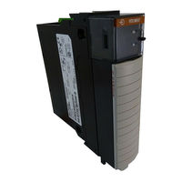
Allen-Bradley 1756-IRT8I Reference Manual (42 pages)
Migrating 6-channel to 8-channel Analog Modules
Brand:
Allen-Bradley
| Category:
Control Unit
| Size: 4.64 MB
Table of Contents
Table of Contents
3
Additional Resources
5
Integrated Architecture Tools
5
Migration Services
5
Overview
5
Preface
5
6- and 8-Channel Modules
7
Chapter 1
7
Product Comparison
7
Wiring
8
Wiring with 1492 Analog Interface Modules
8
Wiring Without 1492 Analog Interface Modules
9
Chapter 2 Emulation Mode Overview
11
Emulation Mode Differences
13
Input Ranges
13
Output Ranges
13
Backplane Power
15
Chapter 3 Current Draw
15
Calibration
16
RPI and RTS Values of 6-Channel Versus 8-Channel Modules
16
RPI and RTS Values of 6- Channel Vs. 8- Channel Modules
16
Cold Junction Compensation on Thermocouple Modules
17
Using an External Loop Supply with the 1756-IF6CIS Module
17
Using an External Loop Supply with the 1756-IF6CIS
17
All 1756-IF6CIS Channels Are Supplying Loop Power
18
One or more 1756-IF6CIS Channels Use External Loop Supply
18
Updating the Firmware
21
Chapter 4
22
Communication Format Support between 6- and 8- Channel Modules
22
Modules
22
Electronic Keying
22
CST Time Stamp Data and Rolling Time Stamp
23
CIP Generic Messages
23
Communication Formats
24
1756-IF8I Communication Formats
24
1756-IRT8I Communication Formats
24
1756-OF8I Communication Formats
25
Configuration
25
Tag Structures
25
Rslogix 5000 Version Support
25
EDS Updates for Rslinx Software
26
Module Info Tab
26
EDS Updates for Rslinx
26
Chapter 5 Status Indicators
27
Status Indicators for the 1756-IF8I Module
27
Status Indicators for the 1756-IRT8I Module
28
Status Indicators for the 1756-OF8I Module
28
Appendix A 1756-IF6I to 1756-IF8I Voltage Mode
29
1756-IF6I to 1756-IF8I Current Mode
30
1756-IF6CIS to 1756-IF8I Modules Provide Loop Power
31
1756-IF6CIS to 1756-IF8I User Supplied Loop Power
32
1756-IR6I to 1756-IRT8I 3-Wire RTD
33
1756-IR6I to 1756-IRT8I 4-Wire RTD
34
1756-IT6I to 1756-IRT8I TC or MV
35
1756-IT6I2 to 1756-IRT8I TC or MV
36
1756-OF6VI to 1756-OF8I Voltage Mode
37
1756-OF6CI to 1756-OF8I Current Mode
38
Index
39
Rockwell Automation Publication 1756-RM011A-EN-P - June
40
Related Products
Allen-Bradley 1756-IR12
Allen-Bradley 1756-IB16
Allen-Bradley 1756-IB16K
Allen-Bradley 1756-IB16DK
Allen-Bradley 1756-IB16IK
Allen-Bradley 1756-IB16ISOE
Allen-Bradley 1756-IB16ISOEK
Allen-Bradley ControlLogix 1756-IC16
Allen-Bradley ControlLogix 1756-IN16
Allen-Bradley ControlLogix 1756-IV32
Allen-Bradley Categories
Control Unit
Controller
I/O Systems
Power Supply
Switch
More Allen-Bradley Manuals