Dell PowerEdge T310 Technical Manual
Hide thumbs
Also See for PowerEdge T310:
- Hardware owner's manual (194 pages) ,
- Technical manualbook (73 pages) ,
- Technical manual (57 pages)
Table of Contents
Quick Links
See also:
Hardware Owner's Manual, Technical Manual
Table of Contents

Related Manuals for Dell PowerEdge T310


Summary of Contents for Dell PowerEdge T310
- Page 1 PowerEdge T310 Technical Guide The T310 delivers enterprise-class performance, redundancy and comprehensive manageability options in a 1-socket tower.
- Page 2 ©Copyright 2011 Dell Inc. All rights reserved. Reproduction or translation of any part of this work beyond that permitted by U.S. copyright laws without the written permission of Dell Inc. is unlawful and strictly forbidden.
-
Page 3: Table Of Contents
DIMM Population Rules ................25 DIMM Slots ....................25 Speed ....................25 Supported Configurations ................26 Chipset ......................27 Direct Media Interface ................27 PCI Express 2.0 Interface ................27 SATA Interface ..................27 PCI Interface .................... 27 PowerEdge T310 Technical Guide... - Page 4 Systems Management ..................43 16.1 Server Management ..................43 16.2 Embedded Server Management ..............44 16.3 Dell Lifecycle Controller and Unified Server Configurator ........44 16.4 Integrated Dell Remote Access Controller ............44 16.5 iDRAC6 Express ..................45 16.6 iDRAC6 Enterprise ..................45 16.7...
- Page 5 Dell Tables Table 1. Comparison of PowerEdge T310 to T110 II and T410..........7 Table 2. Product Features Summary ................ 10 Table 3. Power Supply Status ................15 Table 4. Security Features..................17 Table 5. Power Supply Specifications ............... 19 Table 6.
-
Page 6: Product Overview
1.1 Flexible Technology The Dell PowerEdge T310 is designed to meet the needs of growing small businesses and remote offices of larger organizations and enterprises by offering more features and performance than a basic, entry-level server. With its space-efficient chassis, built-in redundancy features, and comprehensive systems management, the PowerEdge T310 is the ideal reliable 1-socket tower server. -
Page 7: Comparison
Dell 1.5 Comparison Table 1. Comparison of PowerEdge T310 to T110 II and T410 Feature T110 II T310 T410 ® ® Intel Xeon processor Intel Xeon processor 3400 Intel Xeon processor 5500 E3-1200 series series and 5600 series ® Intel Core™ i3-2100... - Page 8 2 internal Non-redundant, Non-redundant 375W or Non-redundant 525W or Power Supplies auto-sensing, 305W (80+) optional hot-plug redundant optional hot-plug redundant 2 x 400W 2 x 580W Non-redundant Non-redundant Non-redundant Fans Non-hot pluggable Non-hot pluggable Non-hot pluggable PowerEdge T310 Technical Guide...
-
Page 9: Key Technologies
Dell 2 Key Technologies The key technologies of the Dell™ PowerEdge™ T310 include the following: • ® ® ® ® Quad-core Intel Xeon processor 3400 series, dual-core Intel Celeron G1101, Intel Pentium G6950, and dual-core Intel Core™ i3 processor 500 series •... -
Page 10: System Features
Dell 3 System Features Table 2 summarizes the product features for the Dell™ PowerEdge™ T310. For the latest information on supported features for the PowerEdge T310, visit Dell.com. Table 2. Product Features Summary Feature Technical Specification Form Factor Tower ®... - Page 11 Application GB means 1 billion bytes and TB equals 1 trillion bytes; actual capacity varies with preloaded material and operating environment and will be less. A maximum of 4 x 8GB UDIMMS is supported (32GB total). PowerEdge T310 Technical Guide...
-
Page 12: Mechanical
Dell 4 Mechanical 4.1 Chassis The Dell™ PowerEdge™ T310 is a tower form-factor server that supports the following features: Flexible power supply (redundant or non-redundant) Common power-supply bay to accommodate two power supplies (non-redundant and redundant) Two fixed hard drive cages (cabled and hot-plug chassis) ... -
Page 13: Front Panel View
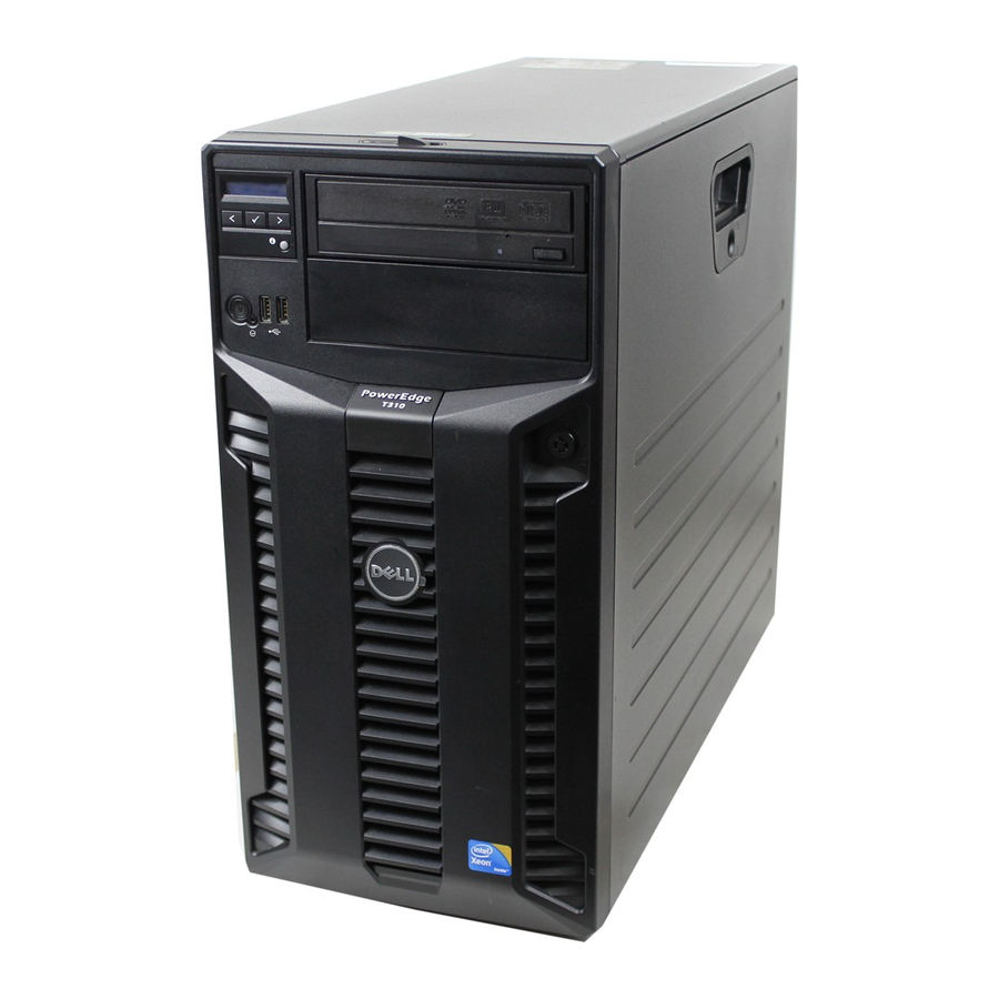
Dell 4.1.2 Front Panel View Figure 2 shows the front view of the PowerEdge T310. Figure 2. Front View See the Front-Panel Features and Indicators section in the About Your System chapter of the PowerEdge T310 Hardware Owner’s Manual on Support.Dell.com/Manuals... -
Page 14: Back Panel View
Both LEDs are used to indicate certain conditions under direction of a storage controller. For more information, see the Hard-Drive Indicator Patterns section in the About Your System chapter in the Dell PowerEdge T310 Systems Hardware Owner’s Manual on Support.Dell.com/Manuals. PowerEdge T310 Technical Guide... -
Page 15: Power Supply Indicators
4.5 Rails and Cable Management The PowerEdge T310 is not a rackable system and does not have a rack kit. However, the T310 can be stored in a rack using a third-party rack tray. For information on power-cord cable-management, see the Installation and Configuration section in the Dell PowerEdge T310 Getting Started Guide on Support.Dell.com/Manuals. -
Page 16: Lcd Panel Configuration
• Non-maskable Interrupt (NMI) button (recessed) For more information on the LCD panel, see the LCD Panel Features (Optional) section in the About Your System chapter in the PowerEdge T310 Hardware Owner’s Manual on Support.Dell.com/Manuals. 4.7.2 LED Panel Configuration Figure 5 shows the LED control panel. -
Page 17: Security
Setup Password Features section in the About Your System chapter in the PowerEdge T310 Hardware Owner’s Manual on Support.Dell.com/Manuals. 4.9 USB Key The PowerEdge T310 has two ports inside the system on the planar for optional USB keys. Some possible applications of the USB key are listed as follows: •... -
Page 18: Field Replaceable Units
The planar contains a 16 K x 8 serial EEPROM to store field replaceable units (FRU) information including Dell part number, part revision level, and serial number. This part is also used as a system event log (SEL) to be used by the baseboard management controller (BMC). -
Page 19: Power, Thermal, Acoustic
5 Power, Thermal, Acoustic 5.1 Power Supplies The Dell™ PowerEdge™ T310 system includes a single non-redundant 375W power supply or an optional redundant 400W power supply. The power supply subsystem provides power to the planar, four internal hard drive bays (cabled hard drive chassis), the hard drive backplane (hot-plug hard drive chassis), and the two 5.25‖... -
Page 20: Heat Dissipation
375W 400W Heat Dissipation 1683 BTU/hr maximum 1672 BTU/hr maximum 5.4 Environmental Specifications Table 7 summarizes the environmental specifications for the PowerEdge T310. For additional information for specific system configurations, see Dell.com/environmental_datasheets. Table 7. Environmental Specifications Specification Operating Requirements Non-Operating Requirements Temperature Ranges 10°C to 35°C... -
Page 21: Energy Star Compliance
One of the sound quality metrics in the Dell specification is prominence ratio of a tone, which is listed in Table 10. -
Page 22: Acoustical Performance
Prominent tones: Criteria of D.6 and D.11 of ECMA-74 11th ed. (2010) are followed to determine if discrete tones are prominent. The system is placed in center of ISO7779 table and acoustic transducer is at front operator position, ref ISO7779 (1999) Section 8.6.1, Position P4. PowerEdge T310 Technical Guide... -
Page 23: Processors
Dell 6 Processors ® ® The Dell™ PowerEdge™ T3 0 system is a one-socket, entry-level server supporting the Intel Xeon ® ® processor 3400 series, the Intel Celeron G1101, the Intel Pentium G6950, and the Intel Core™ i3 500 series processor. -
Page 24: Supported Processors
Dell 6.2 Supported Processors The PowerEdge T310 supports the processors in Table 12. For the latest information on supported processors for the PowerEdge T310, visit Dell.com. Table 12. Supported Processors Model Speed Power Cache Cores ® Intel Celeron G1101 2.26GHz ®... -
Page 25: Memory
DIMMs are configured as 72 bits wide to provide for ECC, which is performed by the memory controller in the processor. 7.4 Speed The PowerEdge T310 supports 1066 MHz and 1333 MHz DDR3 memory. The actual memory frequency is determined by a variety of inputs: •... -
Page 26: Supported Configurations
— — — — — — — — — — — — — — — — — — — — — — — — — — — — — — — — — — *RDIMMs only PowerEdge T310 Technical Guide... -
Page 27: Chipset
3420 processor series chipset and the Intel 3420 or Platform Controller Hub (PCH), a highly integrated I/O controller. A number of high-level features are supported by the chipset on PowerEdge T310, as detailed in the following sections. 8.1 Direct Media Interface Direct Media Interface (DMI) is the chip-to-chip connection between the processor and chipset. -
Page 28: Usb Controllers
(TCO) of the system. These system management functions are designed to report errors, diagnose the system, and recover from system lockups without the aid of an external microcontroller. See Table 14 for details of the Intel 3420 chipset manageability functions. PowerEdge T310 Technical Guide... -
Page 29: Virtualization Technology
SMBus peripherals (slaves). Also, the chipset supports slave functionality, including the Host Notify protocol. Hence, the host controller supports eight command protocols of the SMBus interface (see System Management Bus (SMBus) Specification, Version 2.0): Quick PowerEdge T310 Technical Guide... -
Page 30: Jtag Boundary-Scan
Since JTAG is a serial interface, it eliminates the need to create probe points for every pin in an XOR chain. This eases pin breakout and trace routing and simplifies the interface between the system and a bed-of-nails tester. PowerEdge T310 Technical Guide... -
Page 31: Bios
Dell 9 BIOS The Dell™ PowerEdge™ T310 BIOS is based on the Dell BIOS core, and supports the following features: • Simultaneous Multi-Threading (SMT) support • Processor Turbo Mode support • PCI 2.3 compliant • Plug and Play 1.0a compliant •... -
Page 32: Power Management Features
Power Mgmt. Event Generic When a device signals PME, the system (PME) wakes (if necessary), the OS detects the event, and a Dell-defined ASL routine handles the event; wake-on-LAN is an example of a PME USB Wake Generic Not supported since S1 is not supported... -
Page 33: I2C Block Diagram
Control Memory frequency = MAX Fan algorithm = power Active Power Controller Enable Dell System DBPM (BIOS will not make all P states available to OS) Memory frequency = MAX Fan algorithm = power Custom CPU Power and Performance Management:... -
Page 34: Embedded Nics/Lan On Motherboard (Lom)
10 Embedded NICs/LAN on Motherboard (LOM) ® The Dell™ PowerEdge™ T310 has an embedded dual-port Gigabit Ethernet. The embedded Broadcom 5716 LAN controller is on the T310 planar as an independent Gigabit Ethernet interface device. There is one RJ-45 connector on the back of the system. The firmware for the LOM chip resides in a flash part. -
Page 35: Pci Expansion Cards And Slots
The system supports 25W maximum power for all four PCIe cards. 11.1 Card Quantities and Priorities For information on card quantities and priorities, see the Expansion Cards section in the Installing System Components chapter of the Dell PowerEdge T310 Systems Owner’s Manual on Support.Dell.com/Manuals. 11.2 Card and Slot Dimensions For information about PCIe card and slot dimensions, see the Expansion Cards section in the Installing System Components chapter in the Dell PowerEdge T310 Systems Owner’s Manual on... -
Page 36: Storage
Dell 12 Storage The Dell™ PowerEdge™ T310 supports up to four 3.5‖ internal hard drives or 2.5‖ internal hard drives. The following drive configurations are supported: • 4 x 3.5‖ cabled SATA from motherboard SATA connector • 4 x 3.5‖ cabled SAS or SATA with add-on storage controller •... - Page 37 Add-in SAS/SATA RAID card, RAID 5 —RAID5 (PERC 6/i or H700) Hot-plug SAS/SATA ASSR6 Add-in SAS/SATA RAID card, RAID 6 —RAID6 (PERC 6/i or H700) Hot-plug SAS/SATA ASSR10 Add-in SAS/SATA RAID card, RAID —RAID10 10 (PERC 6/i, H200, or H700) PowerEdge T310 Technical Guide...
-
Page 38: Storage Controllers
A battery is also available for backup. It supports the internal 6 Gb/s backplane interface for internal storage options (SAS, SATA, or SSD HDD). The PowerEdge T310 supports both 512MB and 1GB cache options on the internal H700. PowerEdge T310 Technical Guide... -
Page 39: Optical Drives
Dell 12.4 Optical Drives The PowerEdge T310 supports two internal optical drives and an optional external USB DVD-ROM. The T110 II is able to boot from any internal optical drive. The following internal optical drives configurations are available on the PowerEdge T310: •... -
Page 40: Video
Dell 13 Video ® The Dell™ PowerEdge™ T310 is equipped with a Matrox G200eW with 8MB memory integrated in the ® Nuvoton WPCM450 (Baseboard Management Controller [BMC]). Supported resolutions are listed in Table 19. Table 19. Graphics Video Modes Resolution... -
Page 41: Rack Information
Dell 14 Rack Information Dell does not provide rack support for the Dell™ PowerEdge™ T310. However, the system can be placed in a rack enclosure using a third-party tray. PowerEdge T310 Technical Guide... -
Page 42: Operating Systems
Dell 15 Operating Systems See the following for operating systems support for the Dell™ PowerEdge™ T310: • Operating System Support Matrix for Dell PowerEdge Systems on Dell.com • Dell PowerEdge T310 Systems Getting Started Guide on Support.Dell.com/Manuals PowerEdge T310 Technical Guide... -
Page 43: Systems Management
IT assets. Combining Dell™ PowerEdge™ Servers with a wide selection of Dell developed systems management solutions gives you choice and flexibility, so you can simplify and save in IT environments of any size. To help you meet your server management demands, Dell offers Dell OpenManage™ systems management solutions for: •... -
Page 44: Embedded Server Management
Dell Unified Server Configurator (USC) is a graphical user interface (GUI) that aids in local server provisioning in a pre-OS environment. To access the Unified Server Configurator, press thekey within 10 seconds of the Dell logo appearance during the system boot process. Table 21 details the current functionality enabled by the USC. -
Page 45: Idrac6 Express
16.7 iDRAC6 Enterprise with Virtual Flash Media The iDRAC6 Enterprise can be upgraded by adding the virtual flash (vFlash) media card. This is an 8 GB Dell-branded SD card that enables a persistent 256 MB virtual flash partition. The vFlash media delivers the following key features: •... -
Page 46: Table 22. Features List For Base Management Functionality, Idrac6, And Vflash Media
Update Server power control Serial-over-LAN (with proxy) Serial-over-LAN (no proxy) Power capping Last crash screen capture PowerEdge T310 Technical Guide... - Page 47 Monitoring Real-time Power Graphing Historical Power Counters Logging Features System Event Log RAC Log Trace Log PowerEdge T310 Technical Guide...
-
Page 48: Peripherals
Dell 17 Peripherals The Dell™ PowerEdge™ T310 supports the following USB devices: DVD-ROM DVD+RW USB key (bootable) PowerEdge T310 Technical Guide... -
Page 49: Appendix A. Statement Of Volatility
Statement of Volatility. Configuration option information (pertinent to options such as microprocessors, system memory, remote access controllers, and storage controllers) is available by component separately. The PowerEdge T310 server has the NV components detailed in Table 23. - Page 50 Yes, OSs and applications that conform to data to it during normal operation? the TCG standard can write data to the TPM during normal operation. Access to the NV Storage is controlled by the TPM owner. PowerEdge T310 Technical Guide...
- Page 51 Not write protected Server BMC (Baseboard Management Details Controller) Firmware Flash Memory Size 16MB Flash Type SPI Flash Can user programs or operating system write data to it during normal operation? Purpose Stores the BMC Firmware PowerEdge T310 Technical Guide...
- Page 52 How is this memory write protected? Software write protected To obtain optional component information, please refer to the Dell Statement of Volatility for the individual components. Please direct any questions to your Dell Marketing contact. PowerEdge T310 Technical Guide...
-
Page 53: Appendix B. Certifications
OTAN – CKT Kenya KEBS Kuwait KUCAS Mexico NYCE or NOM Moldova INSM Nigeria SONCAP Norway NEMKO Russia GOST Saudi Arabia KSA ICCP South Africa NRCS Taiwan BSMI UKRTEST or Ukraine UKRSERTCOMPUTER United States NRTL Uzbekistan PowerEdge T310 Technical Guide... -
Page 54: B 3. Electromagnetic Compatibility
The product has been certified and bears the Mark, as applicable, of the Ergonomics, Acoustics and Hygienics authorities as indicated in Table 26. Table 26. Ergonomics, Acoustics and Hygienics Country/Region Authority or Mark Belarus BELLIS Germany Russia GOST PowerEdge T310 Technical Guide... -
Page 55: Appendix C. Additional Information And Options
Dell Appendix C. Additional Information and Options The Dell™ PowerEdge™ T310 system conforms to the industry standards detailed in Table 27. Table 27. Industry Standards Standard URL for Information and Specifications ACPI http://www.acpi.info/ Advance Configuration and Power Interface Specification, v2.0c Energy Star http://www.energystar.gov/index.cfm?c=archives.enterprise_servers... - Page 56 Dell Standard URL for Information and Specifications http://www.usb.org/developers/docs/ Universal Serial Bus Specification, Rev. 2.0 Windows Logo http://www.microsoft.com/whdc/winlogo/hwrequirements.mspx Windows Logo Program System and Device Requirements, v3.10 PowerEdge T310 Technical Guide...