Sony DVP-NS500V Service Manual
Sacd/dvd player
Hide thumbs
Also See for DVP-NS500V:
- Operating instructions manual (96 pages) ,
- Product view (1 page) ,
- Limited warranty (1 page)
Table of Contents
DVP-NS500V / NS700V
SERVICE MANUAL
System
Laser
Semiconductor laser
Signal format system
PAL (NTSC): DVP-NS700V
NTSC: DVP-NS500V
Audio characteristics
DVD (PCM 96 kHz): 2 Hz to 44 kHz (–2 dB ± 2 dB at 44 kHz)
Frequency response
SACD: 2 Hz to 100 kHz (–3 dB ± 2 dB at 50 kHz)
CD: 2 Hz to 20 kHz (±0.5 dB)
Signal-to-noise ratio (S/N ratio)
115 dB (DVD VIDEO) (LINE OUT L/R (AUDIO) 1/2 jacks only)
Harmonic distortion
0.0025 %
Dynamic range
DVD VIDEO/SACD: 103 dB
CD: 99 dB
Wow and flutter
Less than detected value (±0.001% W PEAK)
Outputs
Jack name
Jack type
LINE OUT L/R (AUDIO) (1, 2) Phono jack
DIGITAL OUT (OPTICAL) Optical output jack
DIGITAL OUT (COAXIAL) Phono jack
5.1CH OUTPUT
Phono jack
LINE OUT (VIDEO) (1, 2)
Phono jack
S VIDEO OUT (1, 2)
4-pin mini DIN
COMPONENT
Phono jack
VIDEO OUT (Y,C
,C
)
B
R
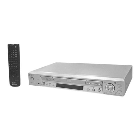
Photo: Titanium gray type
SPECIFICATIONS
Output level
Load impedance
2 Vrms (at 50 kilohms)
Over 10 kilohms
–18 dBm
Wave length: 660 nm
0.5 Vp-p
75 ohms terminated
2 Vrms (50 kilohms)
Over 10 kilohms
1.0 Vp-p
75 ohms, sync negative
Y: 1.0 Vp-p
75 ohms, sync negative
C: 0.3 Vp-p (PAL)
75 ohms terminated
0.286 Vp-p (NTSC)
Y: 1.0 Vp-p
75 ohms, sync negative
C
, C
: 0.7 Vp-p
75 ohms terminated
B
R
RMT-D131A/D131E/D131P/D131O
Saudi Arabia Model
Hong Kong Model
Singapore Model
Middle East Model
General
Power requirements
110 V AC, 60 Hz (NS700V: CH, TW)
120 V AC, 60 Hz (NS500V)
220 to 240 V AC, 50/60 Hz (NS700V: AEP, UK, AUS, E12, ME, RUS, SP)
220 V AC, 50/60 Hz (NS700V: EA, HK, KR)
220 V AC, 60 Hz
Power consumption
15 W
430 × 74 × 256 mm (w/h/d) incl. projecting parts
Dimensions (approx.)
Mass (approx.)
2.8 kg
5 ° C to 35 ° C
Operating temperature
Operating humidity
25 % to 80 %
Supplied accessories
Check that you have the following items:
• Audio/video cord (pinplug × 3 y pinplug × 3) (1)
• Remote commander (remote) RMT-D131A (1)
• Remote commander (remote) RMT-D131E (1)
• Remote commander (remote) RMT-D131P (1)
• Remote commander (remote) RMT-D131O (1)
• Size AA (R6) batteries (2)
Specifications and design are subject to change without notice.
• Abbreviation
AUS
: Australian
KR
: Korea
CH
: Chinese
ME
: Middle East
CND
RUS
: Canadian
: Russian
E12
SP
: 220-240 V AC Area in E
: Singapore
EA
: Saudi Arabia
TW
: Taiwan
HK
: Hong Kong
SACD/DVD PLAYER
US Model
Canadian Model
DVP-NS500V
AEP Model
UK Model
E Model
Australian Model
Russian Model
Chinese Model
Korea Model
Taiwan Model
DVP-NS700V
Table of Contents

Related Manuals for Sony DVP-NS500V


Summary of Contents for Sony DVP-NS500V
-
Page 1: Specifications
DVP-NS500V / NS700V RMT-D131A/D131E/D131P/D131O SERVICE MANUAL US Model Canadian Model DVP-NS500V AEP Model UK Model E Model Australian Model Russian Model Chinese Model Saudi Arabia Model Hong Kong Model Korea Model Singapore Model Photo: Titanium gray type Taiwan Model Middle East Model... - Page 2 OPERATION. REPLACE THESE COMPONENTS WITH DE FONCTIONNEMENT. NE REMPLACER CES COM- SONY PARTS WHOSE PART NUMBERS APPEAR AS POSANTS QUE PAR DES PIÈCES SONY DONT LES SHOWN IN THIS MANUAL OR IN SUPPLEMENTS PUB- NUMÉROS SONT DONNÉS DANS CE MANUEL OU LISHED BY SONY.
-
Page 3: Table Of Contents
TABLE OF CONTENTS Section Title Page Section Title Page Service Note ................4 AV-59 (AUDIO AMP) Schematic Diagram ....4-41 IF-84 Printed Wiring Board ........... 4-43 GENERAL IF-84 (IF CON) Schematic Diagram ......4-45 ER-17 Printed Wiring Board (AEP, UK, RUS) ....4-47 ER-17 (EURO AV) Schematic Diagram Getting Started .............. -
Page 4: Service Note
SERVICE NOTE 1. DISASSEMBLY • This set can be disassembled in the order shown below. Case (Page 2-1) Tray Cover AV-59 Board (Page 2-1) (Page 2-1) Front Panel Mechanism Deck (Page 2-1) (Page 2-2) SI-31 Board Pewer Block IF-84 Board ER-17 Board Optical Pick-up (Page 2-2) - Page 5 2. DISC REMOVAL PROCEDURE 3. HOW TO SERVICE MB-101 BOARD • Use the service jig (J-6090-116-A). (at POWER OFF) 1) Remove the case from the set. (Refer to 2-1) 1) Insert a tapering driver into the aperture of the unit bottom, 2) Remove the AV-59 board.
- Page 6 9) Replace two flexible flat cables as shown in Fig. 4. AV-59 board 1 Flexible flat cable 1 Flexible flat cable (FMA-005A: CN102) (FMA-006A/FMA-006B: CN103) 2 Connector (CN601) 2 Connector (CN501) MB-101 board Note: FMA-006A: EXCEPT AEP, UK, Russian model FMA-006B: AEP, UK, Russian model Fig.
- Page 7 4. CONNECTION OF SERVICE JIG AV-59 CN102 CN203 FFC13P (EXCEPT AEP, UK, Russian)/ FFC27P FFC15P (AEP, UK, Russian) CN601 CN501 HARNESS 9P CN102 FFC26P CN201 MB-101 FFC 9P CN203 Mechanism deck FFC 5P CN204 CN101 CN407 FFC 8P CN403 IF-84 –...
-
Page 8: General
DVP-NS500V/NS700V SECTION 1 This section is extracted from instruction GENERAL manual (3-070-605-11). • A disc that has the adhesive of cellophane Format of discs About this Manual Notes about the Discs tape or a sticker still left on it. Music CD Note •... -
Page 9: Guide To The Control Menu Display
1 TV/DVD switch (69) Rear Panel Remote OPEN/CLOSE button (33) 3 Number buttons (34) The number 5 button has a tactile dot. 4 CLEAR button (38) (69) 5 SACD MULTI/2CH button (36) 6 SACD/CD button (36) C E N T E R R –... -
Page 10: Getting Started
Getting Started Each time you press DISPLAY, the Control Menu display changes as follows: Quick Overview Control Menu display 1 Control Menu display 2 A quick overview presented in this chapter will give you enough information to start using the ADVANCED display (Appears if you select any setting other than “OFF.”... -
Page 11: Hookups
Hookups If you are connecting to a video input jack Hooking Up the Player Connect the yellow plug of the audio/video cord (supplied) to the yellow (video) jacks. You will enjoy standard quality images. Follow Steps 1 to 4 to hook up and adjust the settings of the player. Before you start, turn off the power, check that you have all of the supplied accessories, and insert Yellow (Video) Yellow (Video) - Page 12 SACD/DVD player Connecting to an AV amplifier (having 5.1ch input jacks or a digital input C E N T E R R – AUDIO 1 – L VIDEO 1 jack) and 4 to 6 speakers COAXIAL OPTICAL If your AV amplifier (receiver) has 5.1 channel inputs, use PCM/DTS/ R –...
- Page 13 SACD/DVD player Step 3: Connecting the Power Cord C E N T E R R – AUDIO 1 – L VIDEO 1 COAXIAL OPTICAL R – AUDIO 2 – L VIDEO 2 PCM/DTS/ Plug the player and TV power cords into an AC outlet. DOLBY DIGITAL FRONT REAR...
-
Page 14: Playing Discs
qf Press X/x to select the size of the center speaker. Enjoying the surround sound effects If no center speaker is connected, select “NONE.” Refer to page 80 for each selection item. To enjoy the surround sound effects of this player or your amplifier (receiver), the following SPEAKER SETUP SIZE: items must be set as described below for the audio connection you selected in pages 22 to 25... - Page 15 Notes Using the DVD’s Menu Selecting “ORIGINAL” or Press X/x to select the setting. • Depending on where you stopped the disc, the player • PLAY LIST: plays the titles created may not resume playback from exactly the same “PLAY LIST” on a DVD-RW point.
- Page 16 Various Play Mode Press DISPLAY twice (when playing an Select the title, chapter, or track you To program other titles, chapters, or SACD/CD, press once). want to program. tracks, repeat Steps 4 to 5. Functions (Program Play, Shuffle The Control Menu appears. The programmed titles, chapters, and xWhen playing a DVD VIDEO tracks are displayed in the selected order.
-
Page 17: Searching For A Scene
To turn off the Control Menu Repeating a specific portion (A-B Press X/x to select “SET t,” then Press DISPLAY repeatedly until the Control Repeat Play) press ENTER. Menu is turned off. The “A-B REPEAT” setting display appears. You can select “A-B REPEAT” directly by You can play a specific portion of a title, pressing A-B. -
Page 18: Viewing Information About The Disc
xWhen playing a VIDEO CD Searching for a Title/ Searching by Scene Press ENTER. (TRACK) or (VIEWER) (INDEX) The player starts playback from the Chapter/Track/Index/ selected number. xWhen playing a VIDEO CD with Scene You can divide the screen into 9 subscreens PBC Playback and find the desired scene quickly. -
Page 19: Sound Adjustments
xWhen playing a DVD VIDEO or When playing VIDEO CDs with PBC functions, If the DVD/SACD/CD text does not fit on a single Checking the Playing the scene number and the playing time are displayed. line, you can see the entire text by watching it scroll DVD-RW across the front panel display. -
Page 20: Surround Mode Settings
To turn off the Control Menu The display examples are as follows: Displaying the audio information of SURROUND Mode Settings • PCM (stereo) Press DISPLAY repeatedly until the Control the disc Menu is turned off. PROGRAM FORMAT PCM 96kHz 24bit When you select “AUDIO,”... -
Page 21: Enjoying Movies
Enjoying Movies You can select “SURROUND” directly by REAR Changing the Angles pressing SURROUND. Each time you press the Press c or ENTER. button, the item changes. If you select any setting other than “OFF,” the SURROUND indicator on the The number of the angle changes to “-.”... -
Page 22: Using Various Additional Functions
• DYNAMIC 2: produces a more Adjusting the Playback Enhancing the Playback dynamic picture than DYNAMIC 1 Press X/x to select a level. by further increasing the picture Picture Picture As the value increases, the outlines of (VIDEO EQUALIZER) (DIGITAL VIDEO ENHANCER) contrast and the color intensity. - Page 23 To turn off the Parental Control Area Code Press X/x to select “PLAYER t,” then Press X/x to select “STANDARD,” then function press ENTER. press ENTER. Standard Code Standard Code Set “LEVEL” to “OFF” in Step 8. number number The selection items for “STANDARD” xIf you have not entered a are displayed.
-
Page 24: Settings And Adjustments
VOL +/– Adjust the volume of the TV WIDE MODE Switch to or from the wide Manufacturer Code number mode of a SONY’s wide TV Sony 80, 88, 89, 91 TV/VIDEO Switch the TV’s input source Denon 84, 85, 86... -
Page 25: Custom Settings
If you select “OTHERS t” in “MENU,” 4:3 LETTER BOX Settings for the Display Custom Settings “SUBTITLE,” and “AUDIO,” select and enter a (CUSTOM language code from “Language Code List” (page 90) using the number buttons. (SCREEN SETUP) SETUP) Note 4:3 PAN SCAN Choose settings according to the TV to be Use this to set up playback related and other... - Page 26 • CENTER For connection details, see page 20. D-PCM Select this when the player is Settings for the Speakers Select “DOLBY DIGITAL,” “DTS,” and connected to an audio NONE If you do not connect a center speaker, “48kHz/96kHz PCM” after setting “DIGITAL component lacking a built-in (SPEAKER SETUP) select this.
-
Page 27: Additional Information
Chapter (page 9) display) direct selection buttons on the remote (page , Contact your Sony dealer or local authorized Sections of a picture or a music feature that 34). Sony service facility. are smaller than titles. A title is composed of... -
Page 28: Language Code List
7 times that of a CD. The data This disc consists of dual HD layers and is Technology from Sony developed to produce activated, or playback is completely capacity of a double-layer and single-sided capable of extended play over long periods. - Page 29 CUSTOM SETUP (page 75) SPEAKER SETUP (page 80) AUTO PLAY SIZE FRONT LARGE TIMER SMALL DEMO1 CENTER NONE DEMO2 LARGE DIMMER BRIGHT SMALL DARK REAR NONE LARGE (REAR) PAUSE MODE AUTO LARGE (SIDE) FRAME SMALL (REAR) SMALL (SIDE) PLAYBACK MEMORY SUBWOOFER NONE TRACK SELECTION...
-
Page 30: Disassembly
DVP-NS500V/NS700V SECTION 2 DISASSEMBLY Note: Follow the disassembly procedure in the numerical order given. 2-1. CASE REMOVAL 2-3. TRAY COVER REMOVAL 4 Case 1 Three tapping screws 3 Two claws 2 Tapping screw 4 Tray cover 2 Pull the tray in the direction of arrow B. -
Page 31: Power Block Removal
2-5. POWER BLOCK REMOVAL 2-7. MECHANISM DECK REMOVAL 1 Connector (CN101) 2 Three screws (B3) 3 Two screws 4 Two screws (WHD B3) (WHD B3) 3 Mechanism deck 5 Joint (POWER) 6 Power block 1 Three flexible flat cables 2 Connector (CN201) (CN201, 203, 204) 2-6. -
Page 32: Board Removal
2-9. MB-101 BOARD REMOVAL 2-11. OPTICAL PICK-UP REMOVAL 2 Five screws (B3) 3 MB-101 board 2 Insulator 2 Insulator 1 Insulator screw 2 Insulator 1 Insulator 1 Flexible flat cable screw (CN101) 1 Insulator screw 3 Optical pick-up 2-10. IF-84 BOARD REMOVAL 4 Two screws (B3) 5 Multi pillar 3 Connector (CN201) -
Page 33: Internal Views
2-12. INTERNAL VIEWS DC motor (loading) not supplied DC motor (loading) not supplied Optical pick-up (KHM-240AAA/J1RP) 8-820-144-06... -
Page 34: Circuit Boards Location
2-13. CIRCUIT BOARDS LOCATION Power Block (HS15S1E) (EXCEPT NS500V/NS700V: Taiwan) Power Block (HS15S1J) (NS700V: Taiwan) Power Block (HS15S1U) (NS500V) AV-59 (SWITCHING REGULATOR) (AUDIO/VIDEO OUT) ER-17 (AEP, UK, Russian) (EURO AV) SI-31 (REMOTE COMMANDER RECEIVER) MS-81 MB-101 (LOADING) (SIGNAL PROCESS, SERVO) IF-84 (INTERFACE CONTROL) 2-5 E... -
Page 35: Block Diagrams
DVP-NS500V/NS700V SECTION 3 BLOCK DIAGRAMS 3-1. OVERALL BLOCK DIAGRAM AV-59 BOARD (SEE PAGE 4-39 to 4-42) US, CND MB-101 BOARD (SEE PAGE 4-11 to 4-36) J102 Y, Cb, Cr IC504 IC507 COMPONENT IC303 VIDEO OUT BASE UNIT 64M SDRAM 16M DRAM... -
Page 36: Rf/Servo Block Diagram
DVP-NS500V/NS700V 3-2. RF/SERVO BLOCK DIAGRAM IC201 tl (CD play) IC201 2 (DVD play) IC201 2 (CD play) IC201 tl (DVD play) IC201 rs (DVD play) IC201 rs (CD play) 500 mV/DIV 200 ns/DIV 200 mV/DIV 50 ns/DIV 200 mV/DIV 200 ns/DIV... -
Page 37: Signal Processor Block Diagram
DVP-NS500V/NS700V 3-3. SIGNAL PROCESSOR BLOCK DIAGRAM MB-101 BOARD (2/4) PCLK PCLK (SEE PAGE 4-13, 15, 17) WSAD 0 – 7 WSAD 0 – 7 IC303 SDI 0 – 7 SDI 0 – 7 16M DRAM AUDIO 1 (SEE PAGE 3-11) -
Page 38: System Control Block Diagram
DVP-NS500V/NS700V 3-4. SYSTEM CONTROL BLOCK DIAGRAM MB-101 BOARD (3/4) (SEE PAGE 4-21, 23, 25, 31) IC106 IC107 32M FLASH HA 0 – 21 HA 0 – 21 HA 0 – 21 ı HA 0 – 15 56 – 63 HD 0 – 15 HD 0 –... -
Page 39: Video Block Diagram
DVP-NS500V/NS700V 3-5. VIDEO BLOCK DIAGRAM IC102 wa : AEP, UK, RUS ed : EXCEPT AV-59 BOARD (1/2) • Abbreviation EXCEPT * IC102 36 pin : EXCEPT AEP, UK, RUS AEP, UK, RUS J101 (2/2) (SEE PAGE 4-39) AEP, UK, RUS... -
Page 40: Audio (1) Block Diagram
DVP-NS500V/NS700V 3-6. AUDIO (1) BLOCK DIAGRAM MB-101 BOARD (4/4) (SEE PAGE 4-27, 29, 33) CN601 CDDOUT DSP1DII IC601 DSP2DO SPDIF 32 DSP2DII AUDIO DSP ACH12 160 DSP1CH12I 56 DSP2CH12I DSP2CH78O SDTI/DSDL AOUTL+ ALT+ IC603 159 DSP1CH34I ACH34 IC601 yl,Page 41: Audio (2) Block Diagram
DVP-NS500V/NS700V 3-7. AUDIO (2) BLOCK DIAGRAM AV-59 BOARD (2/2) (SEE PAGE 4-41) IC206 1 D IN OPTICAL DIGITAL CN301 (2/2) J201 Q221 SPDIF BUFFER COAXIAL IC202 J101 (2/2) LINE OUT AUDIO AMP ALT+ ALT– – Q213 AUDIO 1 MUTE ART+ ART–...Page 42: Interface Control Block Diagram
DVP-NS500V/NS700V 3-8. INTERFACE CONTROL BLOCK DIAGRAM IF-84 BOARD (SEE PAGE 4-45) CN403 BZ401 BUZZER SYSTEM CONTROL XIFCS XIFCS (SEE PAGE 3-8) IFBSY IFBSY BUSY S403 S404 S401 XFRRST SURROUND XFRRST /FRRST CN404 AUDIO 2 A_MUTE (SEE PAGE 3-14) /AMUTE VIDEO...Page 43: Power (1) Block Diagram
DVP-NS500V/NS700V 3-9. POWER (1) BLOCK DIAGRAM IF-84 BOARD (SEE PAGE 4-45) HS15S1E BOARD : AEP, UK, AUS, E, EA, HK, KR, ME, RUS, SP, CH (SEE PAGE 4-53) T101 HS15S1U BOARD CN401 CN404 : US, CND CN201 PS402 Q211 EVER+11V...Page 44: Power (2) Block Diagram
DVP-NS500V/NS700V 3-10. POWER (2) BLOCK DIAGRAM AV-59 BOARD (SEE PAGE 4-41) CN102 CN901 • Abbreviation CN101 IC901 L905 AI+5V VIDEO : Russian –5V BUFFER, +11V SELECT +11V SWITCH IC101 –5V REG IC102 ER-17 BOARD (SEE PAGE 4-49) VIDEO 2 IN...Page 45: Printed Wiring Boards And Schematic Diagrams
DVP-NS500V/NS700V DVP-NS500V/NS700V SECTION 4 PRINTED WIRING BOARDS AND SCHEMATIC DIAGRAMS THIS NOTE IS COMMON FOR PRINTED WIRING For schematic diagram: • Caution when replacing chip parts. BOARDS AND SCHEMATIC DIAGRAMS. New parts must be attached after removal of chip. (In addition to this, the necessary mote is printed Be careful not to heat the minus side of tantalum capacitor, in each block.)Page 46: Frame Schematic Diagram
DVP-NS500V/NS700V 4-1. FRAME SCHEMATIC DIAGRAM AEP,UK,RUS CN201 CN401 P-DET P-DET HS15S1U BOARD P-CONT P-CONT ER-17 BOARD :US,CND EVER-11V EVER-11V CN404 7P CN101 7P HS15S1E BOARD M_GND M_GND AU+11V AU+11V CN102 21P M_GND M_GND CN901 AI+5V AI+5V :AEP,UK,RUS,E,ME,AUS, SW+11V SW+11V EA,SP,CH,HK,KR EVER+3.3V...Page 47: Printed Wiring Boards And Schematic Diagrams
DVP-NS500V/NS700V 4-2. PRINTED WIRING BOARDS AND SCHEMATIC DIAGRAMS MS-81 (LOADING), SI-31 (REMOTE COMMANDER RECEIVER) PRINTED WIRING BOARD AND SCHEMATIC DIAGRAM – Ref. No.: MS-81, SI-31 board; 1,000 series – There are a few cases that the part isn't mounted in this model is printed on this diagram.- Page 48 DVP-NS500V/NS700V There are a few cases that the part isn't mounted in this model is printed on this diagram. MB-101 (SIGNAL PROCESS, SERVO) PRINTED WIRING BOARD – Ref. No.: MB-101 board; 2,000 series – MB-101 BOARD (SIDE A) CN101 CN102...
- Page 49 DVP-NS500V/NS700V MB-101 BOARD (SIDE B) D601 D602 D603 IC101 IC103 IC106 IC107 IC201 IC202 IC301 IC303 IC501 IC504 IC507 IC603 IC604 IC801 IC803 IC804 IC807 Q201 Q202 SIGNAL PROCESS, SERVO MB-101 4-10...
Page 50: Mb-101 (Rf Amp, Servo) Schematic Diagram
DVP-NS500V/NS700V MB-101 (RF AMP, SERVO) SCHEMATIC DIAGRAM • See page 4-7 for printed wiring board. The components identified by mark 0 or dotted Les composants identifiés par une marque 0 sont line with mark 0 are critical for safety. – Ref. No.: MB-101 board; 2,000 series –...Page 51: Arp, Servo Dsp) Schematic Diagram
DVP-NS500V/NS700V MB-101 (ARP, SERVO DSP) SCHEMATIC DIAGRAM • See page 4-7 for printed wiring board. – Ref. No.: MB-101 board; 2,000 series – NO MARK:DVD/CD PLAY *:IMPOSSIBLE TO MEASURE THE MB-101 BOARD (2/13) D:DVD PLAY VOLTAGE AT THE MARKED POINTS.Page 52: Mb-101 (Av Decoder) Schematic Diagram
DVP-NS500V/NS700V MB-101 (AV DECODER) SCHEMATIC DIAGRAM • See page 4-7 for printed wiring board. – Ref. No.: MB-101 board; 2,000 series – SIGNAL PATH MB-101 BOARD (3/13) VIDEO SIGNAL AUDIO NO MARK:DVD/CD PLAY SIGNAL D:DVD PLAY CHROMA Y/CHROMA C:CD PLAY...Page 53: Bnr) Schematic Diagram
DVP-NS500V/NS700V MB-101 (BNR) SCHEMATIC DIAGRAM • See page 4-7 for printed wiring board. – Ref. No.: MB-101 board; 2,000 series – • Waveforms SIGNAL PATH 1 IC502 yd : AEP, UK, RUS 3 IC502 yl : EXCEPT AEP, UK, MB-101 BOARD (4/13)Page 54: Drive) Schematic Diagram
DVP-NS500V/NS700V MB-101 (DRIVE) SCHEMATIC DIAGRAM • See page 4-7 for printed wiring board. – Ref. No.: MB-101 board; 2,000 series – SIGNAL PATH MB-101 BOARD (5/13) NO MARK:DVD/CD PLAY D:DVD PLAY SPINDLE SERVO(SPEED AND PHASE) C:CD PLAY TRACKING SERVO DVD/CD CDV MB-101 BOARD (6/13) +3.3V...Page 55: System Control) Schematic Diagram
DVP-NS500V/NS700V MB-101 (SYSTEM CONTROL) SCHEMATIC DIAGRAM • See page 4-7 for printed wiring board. – Ref. No.: MB-101 board; 2,000 series – MB-101 BOARD (6/13) NO MARK:DVD/CD PLAY D:DVD PLAY MB-101 BOARD +3.3V +3.3V C:CD PLAY (1/13,2/13,3/13,4/13,7/13, 9/13,10/13,11/13,12/13) MB-101 BOARD (8/13)Page 56: Clock Generator) Schematic Diagram
DVP-NS500V/NS700V MB-101 (CLOCK GENERATOR) SCHEMATIC DIAGRAM • See page 4-7 for printed wiring board. – Ref. No.: MB-101 board; 2,000 series – MB-101 BOARD (7/13) IC103 NO MARK:DVD/CD PLAY R109 FB101 D:DVD PLAY 27M38 MB-101 BOARD (10/13) FB103 C:CD PLAY...Page 57: Flash Memory, Otp
DVP-NS500V/NS700V MB-101 (FLASH MEMORY, OTP) SCHEMATIC DIAGRAM • See page 4-7 for printed wiring board. *1: Either IC106 or IC107 is used. – Ref. No.: MB-101 board; 2,000 series – MB-101 BOARD (8/13) +3.3V XX MARK:NO MOUNT NO MARK:DVD/CD PLAY...Page 58: Audio Dsp) Schematic Diagram
DVP-NS500V/NS700V MB-101 (AUDIO DSP) SCHEMATIC DIAGRAM • See page 4-7 for printed wiring board. • Waveforms – Ref. No.: MB-101 board; 2,000 series – 1 IC601 yl,Page 59: Mb-101 (2Ch/6Ch Dac) Schematic Diagram
DVP-NS500V/NS700V MB-101 (2ch/6ch DAC) SCHEMATIC DIAGRAM • See page 4-7 for printed wiring board. – Ref. No.: MB-101 board; 2,000 series – MB-101 BOARD (10/13) MB-101 BOARD (6/13) NO MARK:DVD/CD PLAY XDACS P:PAL DVD PLAY D:DVD PLAY N:NTSC DVD PLAY...Page 60: H3Ga) Schematic Diagram
DVP-NS500V/NS700V MB-101 (H3GA) SCHEMATIC DIAGRAM • See page 4-7 for printed wiring board. – Ref. No.: MB-101 board; 2,000 series – • Waveforms MB-101 BOARD (11/13) 1 IC403 w; NO MARK:DVD/CD PLAY C420 C422 C423 0.01u 0.01u 0.01u R447 3.2 Vp-p (33.87 kHz)Page 61: Mb-101 (Saco Decoder) Schematic Diagram
DVP-NS500V/NS700V MB-101 (SACO DECODER) SCHEMATIC DIAGRAM • See page 4-7 for printed wiring board. • Waveforms – Ref. No.: MB-101 board; 2,000 series – 1 IC806 qa NO MARK:DVD/CD PLAY P:PAL DVD PLAY MB-101 BOARD (12/13) D:DVD PLAY N:NTSC DVD PLAY...Page 62: Dsd Dsp) Schematic Diagram
DVP-NS500V/NS700V MB-101 (DSD DSP) SCHEMATIC DIAGRAM • See page 4-7 for printed wiring board. – Ref. No.: MB-101 board; 2,000 series – • Waveforms 1 IC807 ik SIGNAL PATH R864 NO MARK:DVD/CD PLAY XBMCS MB-101 BOARD (13/13) D:DVD PLAY R865...- Page 63 DVP-NS500V/NS700V There are a few cases that the part isn't mounted in this model is printed on this diagram. AV-59 (AUDIO/VIDEO OUT) PRINTED WIRING BOARD – Ref. No.: AV-59 board; 1,000 series – AV-59 BOARD Power Block (HS15S1E) (EXCEPT NS500V/NS700V: Taiwan)
Page 64: Video Buffer) Schematic Diagram
DVP-NS500V/NS700V AV-59 (VIDEO BUFFER) SCHEMATIC DIAGRAM • See page 4-37 for printed wiring board. – Ref. No.: AV-59 board; 1,000 series – AV-59 BOARD (1/2) NO MARK:DVD/CD PLAY AV-59 BOARD (2/2) P_GND L101 100uH EXCEPT AEP,UK,RUS AEP,UK,RUS JL120 J101 RGND...Page 65: Av-59 (Audio Amp) Schematic Diagram
DVP-NS500V/NS700V AV-59 (AUDIO AMP) SCHEMATIC DIAGRAM • See page 4-37 for printed wiring board. – Ref. No.: AV-59 board; 1,000 series – AV-59 BOARD (2/2) R314 100k NO MARK:DVD/CD PLAY R317 D:DVD PLAY 100k Q206 R319 C:CD PLAY 2SB710A-RTX 100k MUTE DRIVE 11.1...- Page 66 DVP-NS500V/NS700V IF-84 (INTERFACE CONTROL) PRINTED WIRING BOARD There are a few cases that the part isn't mounted in this model is printed on this diagram. – Ref. No.: IF-84 board; 1,000 series – IF-84 BOARD Power Block (HS15S1E) CN401 B-13...
Page 67: If Con) Schematic Diagram
DVP-NS500V/NS700V IF-84 (IF CON) SCHEMATIC DIAGRAM The components identified by mark 0 or dotted Les composants identifiés par une marque 0 sont – Ref. No.: IF-84 board; 1,000 series – line with mark 0 are critical for safety. critiques pour la sécurité. Ne les remplacer que Replace only with part number specified.Page 68: Aep, Uk, Rus
DVP-NS500V/NS700V ER-17 (EURO AV) PRINTED WIRING BOARD There are a few cases that the part isn't mounted in this model is printed on this diagram. – Ref. No.: ER-17 board; 1,000 series – – AEP, UK, RUS – ER-17 BOARD...- Page 69 DVP-NS500V/NS700V ER-17 (EURO AV) SCHEMATIC DIAGRAM – Ref. No.: ER-17 board; 1,000 series – – AEP, UK, RUS – ER-17 BOARD NO MARK:DVD/CD PLAY L905 100uH CN901 IC901 JL934 C913 JL937 0.22u RY901 VIDEO BUFFER JL936 SELECT SWITCH IC901 C905...
Page 70: Switching Regulator
DVP-NS500V/NS700V HS15S1E (SWITCHING REGULATOR) PRINTED WIRING BOARD There are a few cases that the part isn't mounted in this model is printed on this diagram. – Ref. No.: HS15S1E board; 3,000 series – – AEP, UK, AUS, E12, EA, HK, KR, CH, ME, RUS, SP –...- Page 71 DVP-NS500V/NS700V HS15S1E (SWITCHING REGULATOR) SCHEMATIC DIAGRAM The components identified by mark 0 or dotted Les composants identifiés par une marque 0 sont – Ref. No.: HS15S1E board; 3,000 series – line with mark 0 are critical for safety. critiques pour la sécurité. Ne les remplacer que Replace only with part number specified.
- Page 72 DVP-NS500V/NS700V HS15S1J (SWITCHING REGULATOR) PRINTED WIRING BOARD There are a few cases that the part isn't mounted in this model is printed on this diagram. – Ref. No.: HS15S1J board; 4,000 series – – TW – HS15S1J BOARD HS15S1J BOARD...
- Page 73 DVP-NS500V/NS700V HS15S1J (SWITCHING REGULATOR) SCHEMATIC DIAGRAM The components identified by mark 0 or dotted Les composants identifiés par une marque 0 sont – Ref. No.: HS15S1J board; 4,000 series – line with mark 0 are critical for safety. critiques pour la sécurité. Ne les remplacer que Replace only with part number specified.
- Page 74 DVP-NS500V/NS700V HS15S1U (SWITCHING REGULATOR) PRINTED WIRING BOARD There are a few cases that the part isn't mounted in this model is printed on this diagram. – Ref. No.: HS15S1U board; 5,000 series – – US, CND – HS15S1U BOARD HS15S1U BOARD...
- Page 75 DVP-NS500V/NS700V HS15S1U (SWITCHING REGULATOR) SCHEMATIC DIAGRAM The components identified by mark 0 or dotted Les composants identifiés par une marque 0 sont – Ref. No.: HS15S1U board; 5,000 series – line with mark 0 are critical for safety. critiques pour la sécurité. Ne les remplacer que Replace only with part number specified.
Page 76: Ic Pin Function Description
DVP-NS500V/NS700V SECTION 5 IC PIN FUNCTION DESCRIPTION...- Page 77 5-2 E...
Page 78: Test Mode
DVP-NS500V/NS700V SECTION 6 TEST MODE 6-1. GENERAL DESCRIPTION 6-3. SYSCON DIAGNOSIS The Test Mode allows you to make diagnosis and adjustment eas- The same contents as board detail check by serial interface can be ily using the remote commander and monitor TV. The instructions, checked from the remote commander.- Page 79 Submenu (2-4) Model Type Model code is displayed. Selecting 2 and subsequent items calls the submenu screen of each Error: Not detected. item. The model code read from the EEPROM is displayed with For example, if “5. Supply” is selected, the following submenu 2-digit hexadecimal number.
- Page 80 4. Servo address, and read address are displayed in this order. How- ever, the message uses same template, and accordingly ex- (4-2) Servo DSP Check Data write → read, and accord check change Address and Data when reading. The following dis- play, for example, Error 12: Read data discord 0x9249, 0x2942 and 0x4294 are written to the RAM ad-...
- Page 81 7. Video Check Items List (7-2) Color Bar AVD color bar command write → Video OUT 2) Version Error: Not detected. (2-2) Revision The command is transferred to the AVD, and the color bar (2-3) ROM Check Sum signals are output from video terminals. (2-4) Model Type They are output from all video terminals (Composite, Y/C, (2-5) Region...
Page 82: Drive Auto Adjustment
1. DVD-SL (single layer) 6-4. DRIVE AUTO ADJUSTMENT [ENTER] Select , insert DVD single layer disc, and press key, and the adjustment will be made through the following steps, then On the Test Mode Menu screen, press key on the remote com- adjusted values will be written to the EEPROM.- Page 83 2. CD 3. DVD-DL (dual layer) [ENTER] [ENTER] Select , insert CD disc, and press key, and the adjust- Select , insert DVD dual layer disc, and press key, ment will be made through the following steps, then adjusted val- and the adjustment will be made through the following steps, then ues will be written to the EEPROM.
Page 84: Drive Manual Operation
0. Disc Check Memory 6-5. DRIVE MANUAL OPERATION Disc Check On the Test Mode Menu screen, select , and the manual opera- tion menu will be displayed. For the manual operation, each servo on/off control and adjustment can be executed manually. 1.- Page 85 Sled Turn ON/OFF the sled servo. Disc Type 1. Disc Type Auto Check CLVA Turn ON/OFF normal servo of spindle 2. DVD SL 12 cm servo. 3. DVD DL 12 cm 4. CD 12cm FCS. Srch Apply same voltage as that of focus 5.
- Page 86 4. Manual Adjustment Auto EQ Auto L.F. Offset Adjusts loop filter offset. Manual Adjustment 1. TRK. Offset 2. Focus Gain Auto Group Delay 3. TRK. Gain 4. Focus Offset 5. Focus Balance 6. Memory Check 6. L.F. Offset 7. EQ BOOST EEPROM DATA 1 -–...
Page 87: Mecha Aging
How to see Emergency History 6-6. MECHA AGING ### Mecha Aging ### Press OPEN key 1: Emergency Code 2: Don't Care These codes are used for verification of software designing. 3: Historical order 1 to 9 Abort: STOP key Emergency Codes List 10: Communication to IC202 (MB-101 board) failed.Page 88: Version Information
6-8. VERSION INFORMATION 6-10. IF CON SELF DIAGNOSTIC FUNCTION 1. IF-84 BOARD (IF CON) TEST MODE ## Version Information ## The front board test mode is the IF CON self diagnostic mode. IF con. Ver : x. xxx (xxxx) The IF CON can diagnose the functions of the front panel boards Group that the IF CON controls.- Page 89 2-2. Operation of Auto Self Check When the Self Check mode becomes active at the AC Power ON or by key input, the test display of the following steps (1) to (4) is repeated. (1) FLD and LED all ON (for 5 seconds) HOUR TRACK CHAP...
- Page 90 2-3. Each Self Check Function Each Self Check function tests the FLD display, LED display, and key input. IC404: Pin No. (Signal) Input Voltage [V] (STOP) (BNRKEY) (O/C) (PLAY) (DISPLAY) (CURSOR) Pin ea Pin ed Pin ef Pin eg Pin eh Pin ej STOP SURROUND...
- Page 91 [PLAY] Key code display (at input of key, Key code: 0Ah) HOUR TRACK CHAP INDEX ANGLE NTSC GROUP TITLE Digital MULTI DMIX P.PCM MPEG REPEAT 1 S H U F F L E PGM A- B At input of faulty voltage TRACK INDEX ANGLE...
- Page 92 2-3-4. Communication Monitoring Display The communication state is monitored and displayed while the key name on the main unit and the remote commander is displayed. When the communication to the System Controller failed, VIDEO CD, DVD, and CD segments turn on. Communication error display (at no key input) TRACK INDEX...
- Page 93 2-3-6. FLD Grid Test Display and SHUTTLE Click Operation Test 2-3-6-1. Transition Keys in Self Check Mode [UP] • on the main unit and the remote commander • SHUTTLE on the remote commander during Grid Test display (This model does not provide JOG/SHUTTLE, and therefore use another DVD remote commander having the JOG/ SHUTTLE) 2-3-6-2.
- Page 94 ( 1G~12G ) ANODE CONNECTION 6-17...
Page 95: Troubleshooting
1-2. CPUCK (33 MHz) is outputted 6-11. TROUBLESHOOTING (communication with ROM is normal) • AVD (IC502) check 6-11-1. Cannot Enter Test Mode Using an oscilloscope, measure the SDCLKO (pin) of the You cannot enter the Test mode when either button has been pressed AVD (IC502) to check that 95 MHz is outputted. - Page 96 3. At button ON, LED lights in green but returns to red (standby state) after several seconds (e.g. it returns to standby state after “SONY DVD” was displayed) There is no regularity between faulty parts and timing when the set returns to the standby state).
Page 97: Electrical Adjustment
DVP-NS500V/NS700V SECTION 7 ELECTRICAL ADJUSTMENT 7-1. POWER SUPPLY CHECK In making adjustment, refer to 7-3. Adjustment Related Parts Arrangement. 1. HS15S1E/HS15S1J/HS15S1U Boards Note: During diagnostic check, the characters and color bars can Mode be seen only with the NTSC monitor. Therefore, for diag-...Page 98: Adjustment Of Video System
7-2. ADJUSTMENT OF VIDEO SYSTEM 3. Checking S Video Output S-CThis checks whether the S-C satisfies the NTSC/PAL Standard. If 1. Video Level Adjustment (MB-101 BOARD) it is not correct, the colors will be too dark or light. ... Page 99: Checking Component Video Output B-Y
5. Checking Component Video Output B-Y 7. Checking RGB Output R (AEP, UK, RUS Model) (Except AEP, UK, RUS Model)This checks RGB output R. If it is incorrect, pictures will not be This checks component video output B-Y. If it is incorrect, cor- displayed correctly in spite of connection to the TV with an EURO rect colors will not be displayed when connected to, for instance, AV connecting cord. Page 100: Checking Rgb Output B
9. Checking RGB Output B (AEP, UK, RUS Model)This checks RGB output B. If it is incorrect, pictures will not be displayed correctly in spite of connection to the TV with an EURO AV connecting cord. In test mode, Push for Syscon Diagnosis and Mode... Page 101: Adjustment Related Parts Arrangement
7-3. ADJUSTMENT RELATED PARTS ARRANGEMENT MB-101 BOARD (SIDE A) RV501 IC502 VIDEO LEVEL HS15S1E/HS15S1J/HS15S1U BOARDS (SIDE A) CN201/CN920 7-6 E...Page 102: Repair Parts List
8-1-1. CASE ASSEMBLY X-3951-925-1 FRONT PANEL ASSY (GOLD) (NS700V) 3-068-047-41 CASE (TITANIUM GRAY) 3-710-901-11 SCREW, TAPPING (BLACK) 3-068-047-51 CASE (GOLD) 4-217-485-01 EMBLEM (5A), SONY (TITANIUM GRAY) 3-710-901-61 SCREW, TAPPING (GOLD, TITANIUM GRAY) 4-963-404-02 EMBLEM (5A), SONY (BLACK, GOLD) 3-068-890-01 CUSHION, REAR LEG...Page 103: Chassis Assembly
8-1-2. CHASSIS ASSEMBLY Ref. No. Part No. Description Remark Ref. No. Part No. Description Remark * 51 1-468-618-11 POWER BLOCK (HS15S1J) (NS700V: TW) * 60 A-6065-755-A MB-101 BOARD, COMPLETE (NS700V: E) * 51 1-468-619-11 POWER BLOCK (HS15S1U) (NS500V) * 60 A-6065-756-A MB-101 BOARD, COMPLETE (NS700V: RUS) * 51 1-468-620-11 POWER BLOCK (HS15S1E) (NS700V: AEP, UK,...Page 104: Mechanism Deck Assembly
8-1-3. MECHANISM DECK ASSEMBLY not supplied not supplied not supplied not supplied not supplied not supplied not supplied supplied supplied supplied not supplied not supplied The components identified by Les composants identifiés par une mark 0 or dotted line with marque 0 sont critiques pour la mark 0 are critical for safety.Page 105: Electrical Parts List
AV-59 8-2. ELECTRICAL PARTS LIST NOTE: The components identified by mark • Due to standardization, replacements in the • Items marked “*” are not stocked since they 0 or dotted line with mark 0 are parts list may be different from the parts speci- are seldom required for routine service.- Page 106 2SB709A-QRS-TX < IC > Q211 8-729-424-02 TRANSISTOR 2SB709A-QRS-TX Q212 8-729-424-02 TRANSISTOR 2SB709A-QRS-TX IC101 8-759-667-17 IC L79M05TLL-SONY-TL IC102 8-759-826-45 IC LA73050-TLM (NS500V/NS700V: E, EA, Q213 8-729-046-97 TRANSISTOR 2SD1938 (F)-T (TX).SO HK, SP, TW, ME, KR, AUS, CH) Q214 8-729-046-97 TRANSISTOR 2SD1938 (F)-T (TX).SO...
- Page 107 AV-59 Ref. No. Part No. Description Remark Ref. No. Part No. Description Remark R117 1-216-021-00 METAL CHIP 1/10W R238 1-208-782-11 METAL CHIP 0.5% 1/10W (NS500V/NS700V: E, EA, HK, SP, TW, ME, KR, AUS, CH) R240 1-208-782-11 METAL CHIP 0.5% 1/10W R118 1-216-021-00 METAL CHIP 1/10W...
- Page 108 AV-59 ER-17 Ref. No. Part No. Description Remark Ref. No. Part No. Description Remark R299 1-216-089-91 RES-CHIP 1/10W C927 1-163-021-91 CERAMIC CHIP 0.01uF C938 1-163-251-11 CERAMIC CHIP 100PF R300 1-216-089-91 RES-CHIP 1/10W C940 1-163-251-11 CERAMIC CHIP 100PF R301 1-216-089-91 RES-CHIP 1/10W R302 1-216-089-91 RES-CHIP...
- Page 109 ER-17 IF-84 Ref. No. Part No. Description Remark Ref. No. Part No. Description Remark RY904 1-515-622-11 RELAY JR906 1-216-295-91 SHORT JR907 1-216-295-91 SHORT JR908 1-216-295-91 SHORT A-6065-745-A IF-84 BOARD, COMPLETE (NS500V/NS700V: JR909 1-216-295-91 SHORT E, EA, HK, SP, TW, ME, KR, AUS, CH) JR910 1-216-295-91 SHORT A-6065-749-A IF-84 BOARD, COMPLETE...
- Page 110 IF-84 Ref. No. Part No. Description Remark Ref. No. Part No. Description Remark R422 1-216-071-00 METAL CHIP 8.2K 1/10W D406 8-719-054-57 DIODE UDZ-TE-17-6.8 R424 1-216-013-00 METAL CHIP 1/10W D408 8-719-071-15 DIODE HZM6.8ZWA1TL R425 1-216-025-11 RES-CHIP 1/10W D409 8-719-071-15 DIODE HZM6.8ZWA1TL R426 1-216-073-91 RES-CHIP 1/10W...
- Page 111 MB-101 Ref. No. Part No. Description Remark Ref. No. Part No. Description Remark A-6065-743-A MB-101 BOARD, COMPLETE (NS500V) C241 1-107-826-11 CERAMIC CHIP 0.1uF A-6065-752-A MB-101 BOARD, COMPLETE C242 1-126-205-11 ELECT CHIP 47uF 6.3V (NS700V: EA, ME) C243 1-162-970-11 CERAMIC CHIP 0.01uF A-6065-753-A MB-101 BOARD, COMPLETE (NS700V: CH) C244...
- Page 112 MB-101 Ref. No. Part No. Description Remark Ref. No. Part No. Description Remark C336 1-162-970-11 CERAMIC CHIP 0.01uF C552 1-162-970-11 CERAMIC CHIP 0.01uF C337 1-162-970-11 CERAMIC CHIP 0.01uF C553 1-162-970-11 CERAMIC CHIP 0.01uF C338 1-162-970-11 CERAMIC CHIP 0.01uF C554 1-162-970-11 CERAMIC CHIP 0.01uF C339 1-162-970-11 CERAMIC CHIP...
- Page 113 MB-101 Ref. No. Part No. Description Remark Ref. No. Part No. Description Remark C828 1-162-970-11 CERAMIC CHIP 0.01uF FL108 1-234-177-21 FILTER, CHIP EMI C829 1-162-970-11 CERAMIC CHIP 0.01uF FL201 1-234-177-21 FILTER, CHIP EMI C830 1-162-970-11 CERAMIC CHIP 0.01uF FL403 1-234-177-21 FILTER, CHIP EMI C831 1-162-970-11 CERAMIC CHIP 0.01uF...
- Page 114 MB-101 Ref. No. Part No. Description Remark Ref. No. Part No. Description Remark R106 1-216-817-11 METAL CHIP 1/16W R157 1-216-081-00 METAL CHIP 1/10W R107 1-216-833-11 METAL CHIP 1/16W (NS700V: HK, SP, TW, KR) R108 1-216-821-11 METAL CHIP 1/16W R157 1-216-089-91 RES-CHIP 1/10W R109 1-216-797-11 METAL CHIP...
- Page 115 MB-101 Ref. No. Part No. Description Remark Ref. No. Part No. Description Remark R238 1-216-839-11 METAL CHIP 1/16W R329 1-216-829-11 METAL CHIP 4.7K 1/16W R239 1-216-839-11 METAL CHIP 1/16W R330 1-216-838-11 METAL CHIP 1/16W R240 1-216-839-11 METAL CHIP 1/16W R331 1-216-822-11 METAL CHIP 1.2K 1/16W...
- Page 116 MB-101 Ref. No. Part No. Description Remark Ref. No. Part No. Description Remark R513 1-216-833-11 METAL CHIP 1/16W R807 1-216-864-11 SHORT R514 1-218-831-11 METAL CHIP 0.5% 1/10W R808 1-216-864-11 SHORT R515 1-218-831-11 METAL CHIP 0.5% 1/10W R516 1-218-831-11 METAL CHIP 0.5% 1/10W R809...
- Page 117 MB-101 MS-81 POWER BLOCK (HS15S1E) Ref. No. Part No. Description Remark Ref. No. Part No. Description Remark R871 1-216-864-11 SHORT C211 1-111-083-11 ELECT 150uF R873 1-216-864-11 SHORT C213 1-126-947-11 ELECT 47uF C221 1-111-082-11 ELECT 100uF R874 1-216-864-11 SHORT C223 1-126-947-11 ELECT 47uF R875 1-216-864-11 SHORT...
- Page 118 POWER BLOCK (HS15S1E) POWER BLOCK (HS15S1J) Ref. No. Part No. Description Remark Ref. No. Part No. Description Remark L311 9-885-012-80 COIL, CHOKE 39uH L511 9-885-012-81 COIL, CHOKE 100uH C613 1-126-947-11 ELECT 47uF L611 9-885-012-81 COIL, CHOKE 100uH C711 1-126-947-11 ELECT 47uF
... - Page 119 POWER BLOCK (HS15S1J) POWER BLOCK (HS15S1U) SI-31 Ref. No. Part No. Description Remark Ref. No. Part No. Description Remark Q311 8-729-265-52 TRANSISTOR 2SC2655 D621 8-719-064-11 DIODE SPR-325MVW (ON/STANDBY) Q411 9-885-006-08 TRANSISTOR 2SD1768S < FUSE > Q611 8-729-265-52 TRANSISTOR 2SC2655 0 F101 Q621 8-729-901-41 TRANSISTOR 2SC1740S...
- Page 120 SI-31 Ref. No. Part No. Description Remark Ref. No. Part No. Description Remark 1-476-889-21 COMMANDER, STANDARD (RMT-D131P) < CAPACITOR > (NS700V: AEP, UK, RUS) 1-476-889-31 COMMANDER, STANDARD (RMT-D131E) C501 1-163-021-91 CERAMIC CHIP 0.01uF (NS700V: E, HK, SP, TW, CH) C502 1-126-947-11 ELECT 47uF 1-476-889-41 COMMANDER, STANDARD (RMT-D131O)
- Page 121 DVP-NS500V/NS700V Sony Corporation 2001H0500-1 9-929-708-11 Home Video Campany © 2001. 8 – 172 – Published by Quality Assurance Dept.