
Related Manuals for Sony CBK-VF01


Summary of Contents for Sony CBK-VF01
- Page 1 HD ELECTRONIC VIEWFINDER CBK-VF01 Sony Corporation OPERATION MANUAL [Japanese/English/French/German/Italian/Spanish/Chinese] CBK-VF01 Printed in Japan (SYM) 2011.01 32 1st Edition 4-265-156-01(1) ©2011...
- Page 2 •...
- Page 3 ....................5 ................5 ................6 ................. 8 ................8 ................9 ..............9 ..........10 ....... 12 ....................12...
- Page 4 •...
- Page 5 CBK-VF01 3.5 LCD 500TV 99.99%...
- Page 6 • •...
- Page 7 f VF n MIRROR REC START h PEAKING i CONTRAST j BRIGHT k TALLY HIGH l ZEBRA m DISPLAY...
- Page 8 • • LOCK LOCK...
- Page 9 MIRROR PEAKING CONTRAST BRIGHT 1 PEAKING 2 CONTRAST 3 BRIGHT...
- Page 11 MIRROR...
- Page 12 DC10.5 17.0 V 680 g • • : mm • 76.8 43.2 mm 16:9...
- Page 13 200 cd/m typical 6500K typical BKW-401 PMW-500 1) PMW-500 Ver. 1.10...
- Page 14 However, there is For the customers in Europe no guarantee that interference will not occur The manufacturer of this product is Sony in a particular installation. If this equipment Corporation, 1-7-1 Konan, Minato-ku, does cause harmful interference to radio or Tokyo, Japan.
-
Page 15: Table Of Contents
Table of Contents Table of Contents Overview ..................... 16 Usage Notes....................16 Names and Functions of Parts ..............17 Attaching the Viewfinder to a Camera ............ 18 Adjusting the Position ..............19 Adjusting the Angle ................ 19 Adjusting the Focus and Image Display ..........20 Raising the Viewfinder Barrel and Eyepiece .......... -
Page 16: Overview
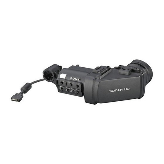
Overview Usage Notes The CBK-VF01 HD Electronic Viewfinder is a Place of use 3.5-inch LCD color viewfinder. When using the viewfinder in low temperature This viewfinder has the following features: environments, dynamic resolution levels may High resolution and wide visual angle... -
Page 17: Names And Functions Of Parts
Viewfinder lens Names and Functions of Do not leave the viewfinder lens facing toward a Parts strong light source, such as sunlight. Burnout of the LCD panel or fire may occur if the lens focuses the sunlight or other strong light source. -
Page 18: Attaching The Viewfinder To A Camera
g Tally indicator Attaching the Viewfinder Lights up when recording is started by a press of the REC START button on the camera, the VTR to a Camera button on the lens, or the VTR button on the remote control unit. When an abnormality occurs, the tally indicator flashes to indicate a warning. -
Page 19: Adjusting The Position
Couple the viewfinder connector to the Adjusting the Angle VF connector (rectangular) on the camera. You can adjust the angle of the viewfinder. VF connector (rectangular) Reversing the display (image/text indication) vertically The viewfinder can be rotated as much as 180 degrees toward the direction facing the subject. -
Page 20: Adjusting The Focus And Image Display
Adjusting the Focus and Raising the Viewfinder Image Display Barrel and Eyepiece You can view the LCD screen inside the Adjusting the focus viewfinder or its mirrored image by raising up the Turn the diopter adjustment ring until the image viewfinder barrel or the eyepiece. - Page 21 Raising the viewfinder barrel Detaching the viewfinder barrel Push the clip on the bottom to release and flip up the viewfinder barrel. It locks at the 120-degree position. Normally use it in the locked position. Although you can open it farther from the lock position, once return it to the closed position to lock it at the 120-degree position again.
-
Page 22: Cleaning The Lcd Screen And Interior
Cleaning the LCD Screen Specifications and Interior General When cleaning the LCD screen or interior of the viewfinder, detach the viewfinder from the Power supply camera, detach the viewfinder barrel from the 10.5 to 17.0 V DC (supplied by the camera) body, and take care not to damage the Power consumption components. - Page 23 Design and specifications are subject to change without notice. Note Always verify that the unit is operating properly before use. SONY WILL NOT BE LIABLE FOR DAMAGES OF ANY KIND INCLUDING, BUT NOT LIMITED TO, COMPENSATION OR REIMBURSEMENT ON ACCOUNT OF THE LOSS OF PRESENT...
- Page 24 E3 (urbain extérieur) et E4 (environnement EMC contrôlé, ex. studio de télévision). Pour les clients en Europe Le fabricant de ce produit est Sony Corporation, 1-7-1 Konan, Minato-ku, Tokyo, Japon. Le représentant autorisé pour EMC et la sécurité des produits est Sony Deutschland GmbH, Hedelfinger Strasse 61, 70327 Stuttgart, Allemagne.
- Page 25 Table des matières Présentation....................26 Remarques d’utilisation ................26 Nomenclature et fonctions des éléments ..........27 Fixation du viseur sur une caméra............29 Ajustement de la position..............29 Ajustement de l’angle ..............30 Ajustement de la mise au point et de l’affichage de l’image....30 Relèvement de l’oculaire et du barillet du viseur ........
-
Page 26: Présentation
Présentation Remarques d’utilisation Le viseur électronique HD CBK-VF01 est un Lieu d’utilisation viseur couleur LCD de 3,5 pouces. Lorsque vous utilisez le viseur dans des Ce viseur présente les caractéristiques suivantes : environnements à basse température, les niveaux Haute résolution et grand angle visuel de résolution dynamique peuvent diminuer... -
Page 27: Nomenclature Et Fonctions Des Éléments
Objectif du viseur Nomenclature et Ne laissez pas l’objectif du viseur face à une fonctions des éléments source puissante de lumière, comme la lumière solaire. Il se peut que l’écran LCD grille ou qu’un incendie se produise si l’objectif concentre la lumière du soleil ou d’une autre source puissante de lumière. - Page 28 f Barillet du viseur n Interrupteur MIRROR Relevez-le ou retirez-le lorsque la situation le L’affichage de l’image sur l’écran est inversé nécessite. horizontalement ou verticalement lorsque vous relevez ou tournez le barillet du viseur. Utilisez g Indicateur de signalisation cet interrupteur pour commander l’affichage de Cet indicateur s’allume lorsque l’enregistrement l’image dans de telles situations.
-
Page 29: Fixation Du Viseur Sur Une Caméra
Branchez la fiche du viseur dans le Fixation du viseur sur connecteur VF (rectangulaire) de la caméra. une caméra Connecteur VF (rectangulaire) ATTENTION Lorsque le viseur est fixé, ne laissez pas l’objectif du viseur en face du soleil. Les rayons du soleil directs peuvent entrer par l’objectif, se concentrer dans le viseur et provoquer un incendie. -
Page 30: Ajustement De L'angle
Ajustement de l’angle Ajustement de la mise au point et de l’affichage Vous pouvez ajuster l’angle du viseur. de l’image Ajustement de la mise au point Tournez la bague d’ajustement de la dioptrie jusqu’à ce que l’image soit nette. Inversement vertical de l’affichage (image/indications textuelles) Vous pouvez tourner le viseur au maximum de 180 degrés dans la direction du sujet. -
Page 31: Relèvement De L'oculaire Et Du Barillet Du Viseur
Relèvement du barillet du viseur Relèvement de Poussez la languette à la base pour déverrouiller l’oculaire et du barillet et sortir le barillet du viseur. Il se verrouille à la position 120 degrés. du viseur Vous pouvez voir l’écran LCD dans le viseur ou son image inversée en relevant l’oculaire ou le barillet du viseur. -
Page 32: Nettoyage De L'écran Lcd Et De L'intérieur
Retrait du barillet du viseur Nettoyage de l’écran LCD et de l’intérieur Lors du nettoyage de l’écran LCD ou de l’intérieur du viseur, retirez le viseur de la caméra, retirez le barillet du viseur du boîtier, et faites attention à ne pas endommager les composants. -
Page 33: Spécifications
255 (10 Remarque Vérifiez toujours que l’appareil fonctionne correctement avant l’utilisation. Sony n’assumera pas de responsabilité pour les dommages de quelque sorte qu’ils soient, incluant mais ne se limitant pas à la compensation ou au remboursement, à cause de Ecran LCD la perte de profits actuels ou futurs suite à... - Page 34 (kommerzieller und in beschränktem Maße industrieller Bereich), E3 (Stadtbereich im Freien) und E4 (kontrollierter EMV-Bereich, z.B. Fernsehstudio). Für Kunden in Europa Der Hersteller dieses Produkts ist Sony Corporation, 1-7-1 Konan, Minato-ku, Tokyo, Japan. Der autorisierte Repräsentant für EMV und Produktsicherheit ist Sony Deutschland GmbH, Hedelfinger Strasse 61, 70327 Stuttgart, Deutschland.
- Page 35 Inhalt Überblick ....................36 Hinweise zur Bedienung................36 Namen und Funktionen der Teile ............37 Anbringen des Suchers an der Kamera........... 39 Justieren der Position ..............39 Einstellen der Neigung..............40 Einstellen des Fokus und der Bildanzeige ..........40 Anheben des Suchertubus und des Suchereinblicks....... 41 Reinigen des LCD-Bildschirms und des Inneren des Suchers....
-
Page 36: Überblick
Überblick Hinweise zur Bedienung Der CBK-VF01 HD Electronic Viewfinder ist ein Einsatzort 3,5-Zoll-Farbsucher mit LCD-Technologie. Wenn der Sucher in Umgebungen mit niedriger Der Sucher weist die folgenden Eigenschaften Temperatur verwendet wird, stehen unter auf: Umständen in der ersten Zeit nach dem Hohe Auflösung und breiter Blickwinkel... -
Page 37: Namen Und Funktionen Der Teile
Sucherobjektiv Namen und Funktionen Lassen Sie das Sucherobjektiv nicht längere Zeit der Teile in Richtung einer starken Lichtquelle zeigen, z. B. in die Sonne. Wenn das Sonnenlicht oder Licht von einer anderen starken Lichtquelle von der Linse gebündelt wird, kann dies zu Beschädigungen der LCD-Anzeige oder Bränden führen. - Page 38 g Kontrolleuchte o Sucherkabel Leuchtet, wenn die Aufzeichnung durch Drücken p Mikrofonhalter der Taste REC START an der Kamera, der Taste VTR am Objektiv oder der Taste VTR auf der Fernbedienung gestartet wurde. Blinkt zur Warnung bei Unregelmäßigkeiten. h Regler PEAKING Drehen Sie diesen Regelung im Uhrzeigersinn, um die Bildschärfe einzustellen und die Fokussierung zu erleichtern.
-
Page 39: Anbringen Des Suchers An Der Kamera
Verbinden Sie den Sucheranschluss mit Anbringen des Suchers dem Anschluss VF (rechteckig) der Kamera. an der Kamera Anschluss VF (rechteckig) VORSICHT Bei angebrachtem Sucher darf das Sucherobjektiv nicht in Richtung der Sonne zeigen. Andernfalls könnte durch das Objektiv eintretendes Sonnenlicht m Sucher gebündelt werden und einen Brand verursachen. -
Page 40: Einstellen Der Neigung
Einstellen der Neigung Einstellen des Fokus und der Bildanzeige Sie können die Neigung des Suchers einstellen. Einstellen des Fokus Stellen Sie durch Drehen des Diopter- Einstellrings die optimale Bildschärfe ein. Vertikales Spiegeln der Anzeige (Text- Bild-Richtung) Der Sucher kann um bis zu 180 Grad in Richtung Motiv gedreht werden. -
Page 41: Anheben Des Suchertubus Und Des Suchereinblicks
Anheben des Suchertubus Anheben des Drücken Sie auf den Clip an der Unterseite des Suchertubus und des Gerätes, um den Suchertubus zu lösen und hochzuklappen. Suchereinblicks Er wird in einer 120-Grad-Position arretiert. Sie können den LCD-Bildschirm im Sucher oder dessen Spiegelbild betrachten, indem Sie den Suchertubus oder den Suchereinblick anheben. - Page 42 Abnehmen des Suchertubus Horizontales Spiegeln der Anzeige (Text- Bild-Richtung) Indem Sie den Schalter MIRROR auf L/R stellen, können Sie das Bild und weitere auf dem Bildschirm angezeigte Informationen horizontal spiegeln. Drücken Sie zum Lösen des Suchertubus auf den Clip an der Unterseite des Gerätes.
-
Page 43: Reinigen Des Lcd-Bildschirms Und Des Inneren Des Suchers
Reinigen des LCD- Technische Daten Bildschirms und des Inneren des Suchers Allgemein Nehmen Sie zum Reinigen des LCD-Bildschirms oder des Inneren des Suchers den Sucher von der Stromversorgung Kamera ab und lösen Sie den Suchertubus vom 10,5 bis 17,0 V - (durch die Kamera) Sucher. - Page 44 Version 1.10 erforderlich. Änderungen, die dem technischen Fortschritt dienen, bleiben vorbehalten. Hinweis Bestätigen Sie vor dem Gebrauch immer, dass das Gerät richtig arbeitet. SONY KANN KEINE HAFTUNG FÜR SCHÄDEN JEDER ART, EINSCHLIESSLICH ABER NICHT BEGRENZT AUF KOMPENSATION ODER ERSTATTUNG, AUFGRUND VON...
- Page 45 (residenziali), E2 (commerciali e industriali leggeri), E3 (esterni urbani) e E4 (ambienti EMC controllati, ad esempio studi televisivi). Per i clienti in Europa Il fabbricante di questo prodotto è la Sony Corporation, 1-7-1 Konan, Minato-ku, Tokyo, Giappone. La rappresentanza autorizzata per EMC e la sicurezza dei prodotti è...
- Page 46 Indice Descrizione generale .................. 47 Note per l’uso ..................... 47 Denominazione e funzioni dei componenti ..........48 Collegamento del mirino a una telecamera ..........50 Regolazione della posizione............50 Regolazione dell’angolo..............51 Regolazione della messa a fuoco e del display immagini......51 Sollevamento del cilindro del mirino e dell’oculare .......
-
Page 47: Descrizione Generale
Descrizione generale Note per l’uso Il mirino elettronico HD CBK-VF01 è un mirino Luogo d’impiego 3,5 pollici a colori LCD. Quando si utilizza il mirino in ambienti a bassa Questo mirino offre le seguenti caratteristiche: temperatura, i livelli di risoluzione dinamica... -
Page 48: Denominazione E Funzioni Dei Componenti
Ottica del mirino Denominazione e Non lasciare l’ottica del mirino rivolta verso una funzioni dei componenti sorgente luminosa di elevata intensità, ad esempio la luce solare diretta. Se l’ottica mette a fuoco tale sorgente luminosa di elevata intensità, potrebbero verificarsi guasti e fenomeni di “burnout”... - Page 49 g Indicatore TALLY L/R: Inverte l’immagine orizzontalmente. OFF: Non inverte l’immagine orizzontalmente. Si accende quando la registrazione viene avviata B/T: Inverte l’immagine verticalmente. premendo il tasto REC START sulla telecamera o il tasto VTR sull’obiettivo o il tasto VTR sul o Cavo del mirino telecomando.
-
Page 50: Collegamento Del Mirino A Una Telecamera
Accoppiare il connettore del mirino al Collegamento del mirino connettore VF (rettangolare) della telecamera. a una telecamera Connettore VF (rettangolare) ATTENZIONE Quando il mirino è collegato, non lasciare l’obiettivo del mirino rivolto verso il sole. La luce diretta del sole potrebbe entrare attraverso l’obiettivo, venire messa a fuoco nel mirino e provocare un incendio. -
Page 51: Regolazione Dell'angolo
Regolazione dell’angolo Regolazione della messa a fuoco e del È possibile regolare l’angolo del mirino. display immagini Regolazione della messa a fuoco Ruotare il regolatore delle diottrie fino a quando l’immagine visualizzata non diventa nitida. Inversione dello schermo (visualizzazione immagini/testo) in senso verticale Il mirino può... -
Page 52: Sollevamento Del Cilindro Del Mirino E Dell'oculare
Sollevamento del cilindro del mirino Sollevamento del Premere il clip sulla base per sganciare e ribaltare cilindro del mirino e il cilindro del mirino. Si blocca in posizione 120 gradi. dell’oculare È possibile guardare lo schermo LCD all’interno del mirino o la sua immagine rispecchiata, sollevando il cilindro del mirino o l’oculare. -
Page 53: Pulizia Dello Schermo Lcd E Della Parte Interna
Rimozione del cilindro del mirino Pulizia dello schermo LCD e della parte interna Quando si pulisce lo schermo LCD o l’interno del mirino, rimuovere il mirino dalla telecamera, staccare il cilindro del mirino dal corpo e fare attenzione a non danneggiare i componenti. Per maggiori dettagli sulla rimozione del cilindro del mirino, consultare “Collegamento del mirino a una telecamera”... -
Page 54: Caratteristiche Tecniche
Nota Verificare sempre che l’apparecchio stia funzionando correttamente prima di usarlo. LA SONY NON SARÀ RESPONSABILE DI DANNI DI QUALSIASI TIPO, COMPRESI, MA SENZA LIMITAZIONE A, RISARCIMENTI O RIMBORSI A CAUSA DELLA PERDITA DI PROFITTI ATTUALI O... - Page 55 (exteriores urbanos), y E4 (entorno con EMC controlada, p. ej., estudio de televisión). Para los clientes de Europa El fabricante de este producto es Sony Corporation, con dirección en 1-7-1 Konan, Minato-ku, Tokio, Japón. El Representante autorizado para EMC y...
- Page 56 Contenido Descripción general ................... 57 Notas de uso....................57 Nombres y funciones de los componentes..........58 Acople del visor a una cámara..............60 Ajuste de la posición ............... 60 Ajuste del ángulo................61 Ajuste del enfoque y la visualización de la imagen......... 61 Cómo se levantan el cilindro del visor y el ocular........
-
Page 57: Descripción General
Descripción general Notas de uso El Visor electrónico HD CBK-VF01 es un visor Lugar de utilización en color con pantalla LCD de 3,5 pulgadas. Cuando utilice el visor en entornos de baja Este visor incluye las siguientes funciones: temperatura, es posible que los niveles de Alta resolución y ángulo de visión panorámico... -
Page 58: Nombres Y Funciones De Los Componentes
Objetivo del visor Nombres y funciones de No deje el objetivo del visor orientado hacia una los componentes fuente de luz intensa, como la luz solar. Si el objetivo enfocara la luz del sol o cualquier otra fuente de luz intensa, el panel LCD podría quemarse o podría originarse un incendio. - Page 59 g Indicador de posición OFF: la imagen no se invierte. B/T: permite invertir la imagen verticalmente. Se ilumina cuando se inicia la grabación mediante la pulsación del botón REC START de la cámara, o Cable del visor el botón VTR del objetivo o el botón VTR de la unidad de control remoto.
-
Page 60: Acople Del Visor A Una Cámara
Acople el conector del visor al conector Acople del visor a una VF (rectangular) de la cámara. cámara Conector VF (rectangular) PRECAUCIÓN Cuando el visor esté acoplado, no deje el objetivo del visor orientado hacia el sol. La luz solar directa podría entrar a través del objetivo, quedar enfocada en el visor y provocar un incendio. -
Page 61: Ajuste Del Ángulo
Ajuste del ángulo Ajuste del enfoque y la visualización de la Permite ajustar el ángulo del visor. imagen Ajuste del enfoque Gire el anillo de ajuste de dioptrías hasta que la imagen esté lo más definida posible. Inversión de la visualización (imagen/ indicación de texto) de manera vertical Es posible girar el visor como máximo 180 grados hacia la dirección que queda mirando al sujeto. -
Page 62: Cómo Se Levantan El Cilindro Del Visor Y El Ocular
Cómo se levanta el cilindro del visor Cómo se levantan el Presione el clip de la parte inferior para liberarlo cilindro del visor y el y tire hacia arriba del cilindro del visor. Se bloquea en la posición de los 120 grados. ocular Es posible visualizar la pantalla LCD dentro del visor o su imagen invertida al levantar el cilindro... -
Page 63: Limpieza De La Pantalla Lcd Y Del Interior
Desmontaje del cilindro del visor Limpieza de la pantalla LCD y del interior Cuando limpie la pantalla LCD o el interior del visor, extraiga el visor de la cámara, desmonte el cilindro del visor del cuerpo de la cámara y asegúrese de no dañar ninguno de los componentes. -
Page 64: Especificaciones
El diseño y las especificaciones están sujetos a cambios sin previo aviso. Nota Verifique siempre que esta unidad funciona correctamente antes de utilizarlo. SONY NO SE HACE RESPONSIBLE POR DAÑOS DE NINGÚN TIPO, INCLUYENDO PERO NO LIMITADO A LA COMPENSACIÓN O PAGO POR LA PÉRDIDA DE GANANCIAS... - Page 65 中文 机型名称:高清电子寻像器 使用产品前请仔细阅读本书,并请妥善 保管。 重要 设备铭牌位于底部。...
- Page 66 目录 概述....................67 使用注意事项 ................... 67 部件名称及功能................68 将取景器连接到摄像机上 ..............70 调整位置..................70 调整角度..................71 调整焦距和图像显示 ................ 71 抬起取景器镜头筒和接目镜.............. 72 清洁 LCD 屏幕及内部 ..............73 规格....................74 目录...
-
Page 67: 使用注意事项
概述 使用注意事项 CBK-VF01 HD 电子取景器是 3.5 英寸的 使用地点 LCD 彩色取景器。 在低温环境下使用取景器时,在开启电 此取景器有以下特点: 源后的片刻,动态分辨率水平可能会下 降。 高分辨率及宽可视角 取景器配有一块高分辨率的 LCD,水平 LCD 面板上的亮点或闪烁像素 分辨率达到 500 TV 线或更高。 此监视器所用 LCD 面板是采用高精密技 即使取下接目镜,也可通过取景器的大 术生产的,有效像素率达至少达到 LCD 屏幕轻松拍摄。 99.99%。因此有很少一部分像素可能会 稳定的图像 表现为 “亮点” ,或者始终是暗点 (黑 无论什么屏幕亮度, LCD 屏幕都能提供 色) 、变亮 (红色、绿色或蓝色)或者... -
Page 68: 部件名称及功能
取景器镜头 部件名称及功能 请勿让取景器镜头直面强光源,例如日 光。 如果镜头将阳光或其他强光源光线聚 焦,可能会烧毁 LCD 面板或起火。 维护 • 使用吹灰器清除屏幕上的灰尘。 • 请勿使用稀释剂之类的溶剂清洁屏幕。 a 插头 连接至摄像机上的 VF 接口 (矩形) 。 b 制动器 左右滑动时,防止取景器从摄像机上掉 落。 c 取景接目罩 d 屈光度调节环 可实现最佳焦距调整。 e 接目镜 根据情况将接目镜抬起或拆下。 f 取景器镜头筒 根据情况将取景器镜头筒抬起或拆下。 部件名称及功能... - Page 69 B/T:垂直翻转图像。 g 讯号指示灯 在按下摄像机上的 REC START 按钮、 o 取景器电缆 镜头上的 VTR 按钮或遥控器上的 VTR 按钮开始拍摄时亮起。 p 麦克风支架 如果发生异常,讯号指示灯会闪烁示 警。 h PEAKING 控制 顺时针转动此控件可调整图像锐度,使 调焦更轻松。它对摄像机的输出信号没 有影响。 i CONTRAST 控制 调整屏幕的对比度。它对摄像机的输出 信号没有影响。 j BRIGHT 控制 调整屏幕的亮度。它对摄像机的输出信 号没有影响。 k TALLY 开关 控制讯号指示灯。 HIGH:讯号指示灯亮度设置为高。 OFF:禁用讯号指示灯。 LOW:讯号指示灯亮度设置为低。...
-
Page 70: 将取景器连接到摄像机上
将取景器接口连接到摄像机的 VF 接 将取景器连接到摄像机 口 (矩形)上。 上 VF 接口 (矩形) 注意 连接取景器后,请勿让取景器镜头朝向 太阳。直射阳光会透过透镜而在取景器 上聚焦,从而导致起火。 注意 在连接取景器时,请注意以下几点。 • 在将取景器接口与摄像机的 VF 接口 (矩形)连接之前,务必先关闭摄像机 电源。如果在摄像机电源打开时进行 拆下取景器 连接,取景器可能无法正常工作。 您可以倒过来执行连接步骤来拆下取景 • 将取景器接口牢固地连接到摄像机的 器,但是还有一个额外操作:从定位靴 VF 接口 (矩形)上。如果连接得不牢 上拆下取景器时,先拉起制动器。 (请 固,视频上可能会出现干扰,或者讯 参见步骤 1 中的图。 ) 号指示灯可能无法正常工作。 调整位置 1 在摄像机上旋松取景器左右定位... -
Page 71: 调整角度
调整角度 调整焦距和图像显示 可调整取景器的角度。 调整焦距 转动屈光度调节环,直到图像最清晰。 垂直翻转显示 (图像 / 文字显示) 可将取景器朝着拍摄对象的方向最多旋 转 180 度。 旋转后,屏幕中显示的图像及其他信息 会上下颠倒显示。要恢复正常显示,可 将 MIRROR 开关设置到 B/T 位置。 屈光度调节环 调整图像显示 通过如下控件调整显示亮度、对比度以 及峰值。 1 PEAKING 控制 2 CONTRAST 控制 3 BRIGHT 控制 调整焦距和图像显示... -
Page 72: 抬起取景器镜头筒和接目镜
抬起取景器镜头筒 抬起取景器镜头筒和接 按下底部的卡扣松开取景器镜头筒,然 目镜 后将其向上掀起。 取景器镜头筒会在 120 度位置处锁定。 通过抬起取景器镜头筒或接目镜,可以 查看取景器内部的 LCD 屏幕或者其镜 像图像。 本节说明如何抬起及拆下取景器镜头 筒。也可以采用相同的方式抬起和拆下 接目镜。 通常在锁定位置进行使用。 LCD 屏幕 尽管可以在距锁定位置更远的距离打开 取景器镜头筒,但是一旦使其回到闭合 位置,便会再次在 120 度位置处锁定。 抬起取景器镜头筒和接目镜... -
Page 73: 清洁 Lcd 屏幕及内部
拆下取景器镜头筒 清洁 LCD 屏幕及内部 如需清洁 LCD 屏幕及取景器内部,请 从摄像机上拆下取景器,然后拆下取景 器镜头筒,请小心不要损坏组件。 有关如何拆下取景器的详细信息,请参 阅 “将取景器连接到摄像机上” (第 页) 。 有关如何拆下取景器镜头筒的详细信 息,请参阅 “拆下取景器镜头筒” (第 页) 。 清除屏幕灰尘 使用吹灰器。 注意 请勿使用稀释剂等溶剂。 在恶劣的环境中使用取景器后 在恶劣的环境中 (例如沙滩、多尘区域 或温泉度假村)使用取景器后,请检查 以下各点。 • 使用气刷小心地去除取景器内部的所 有沙尘。 • 清洁接口的触点。 • 检查取景器是否正常工作。 按下底部的卡扣将取景器镜头筒松 开。 向上掀起取景器镜头筒。 滑动取景器镜头筒相对侧顶部的旋... - Page 74 操作手册 (1) 20 ℃至+60 ℃ – 重量 选配附件 约680 g 取景器旋转组件 外部尺寸 BKW-401 单位:mm 相关附件 固态存储卡摄录一体机 PMW-500 1) 要将取景器连接至PMW-500,摄录 一体机上的固件版本必须为1.10或更 高。 设计与规格如有变更,恕不另行通知。 注意 在使用前请始终确认本机运行正常。 无论保修期内外或基于任何理由, SONY 对任何损坏概不负责。由于 本机故障造成的现有损失或预期利 3.5英寸彩色TFT透反式LCD 图像显示区尺寸 润损失,不作 (包括但不限于)退 76.8 × 43.2 mm (H/V, 16:9宽高比) 货或赔偿。 规格...
- Page 75 The material contained in this manual consists of information that is the property manutenzione dell’apparecchio ivi of Sony Corporation and is intended solely descritto, senza previo permesso scritto di Sony Corporation. for use by the purchasers of the equipment described in this manual.