Table of Contents
HYDROBOX
SERVICE MANUAL
[Model name]
EHSD-MEC
EHSD-VM2C
EHSC-MEC
EHSC-VM2C
EHSC-VM2EC
EHSC-VM6C
EHSC-VM6EC
EHSC-YM9C
EHSC-YM9EC
EHSC-TM9C
ERSD-VM2C
ERSC-MEC
ERSC-VM2C
EHPX-VM2C
EHPX-YM9C
HYDROBOX
[Service Ref.]
EHSD-MEC.UK
EHSD-VM2C.UK
EHSC-MEC.UK
EHSC-VM2C.UK
EHSC-VM2EC.UK
EHSC-VM6C.UK
EHSC-VM6EC.UK
EHSC-YM9C.UK
EHSC-YM9EC.UK
EHSC-TM9C.UK
ERSD-VM2C.UK
ERSC-MEC.UK
ERSC-VM2C.UK
EHPX-VM2C.UK
EHPX-YM9C.UK
MAIN REMOTE
CONTROLLER
R410A
CONTENTS
1. REFERENCE MANUAL ................................... 2
2. SAFETY PRECAUTION ................................... 3
3. SPECIFICATIONS ............................................ 6
4. PART NAMES AND FUNCTIONS .................. 7
5. OUTLINES AND DIMENSIONS ....................... 8
6. WIRING DIAGRAM ........................................ 10
7. FIELD WIRING ............................................... 16
8. WATER SYSTEM DIAGRAM ......................... 18
9. CONTROLS ................................................... 21
10. TROUBLESHOOTING ................................... 41
11. DISASSEMBLY PROCEDURE ...................... 58
12. SUPPLEMENTARY INFORMATION ............. 79
13. SERVICE AND MAINTENANCE ................... 80
PARTS CATALOG (OCB571)
October 2014
No. OCH571
Note:
• This manual describes
only service data of
Hydrobox.
• RoHS compliant products
have mark on the
spec name plate.
Table of Contents
Troubleshooting

Related Manuals for Mitsubishi Electric EHSD-MEC.UK


Summary of Contents for Mitsubishi Electric EHSD-MEC.UK
-
Page 1
HYDROBOX October 2014 No. OCH571 SERVICE MANUAL R410A [Model name] [Service Ref.] Note: EHSD-MEC.UK EHSD-MEC • This manual describes only service data of EHSD-VM2C.UK EHSD-VM2C Hydrobox. • RoHS compliant products EHSC-MEC.UK EHSC-MEC have
mark on the EHSC-VM2C.UK spec name plate. -
Page 2: Reference Manual
REFERENCE MANUAL OUTDOOR UNIT'S SERVICE MANUAL Service Ref. Service Manual No. PUHZ-W50/85VHA(-BS) PUHZ-W50/85VHAR1(-BS) OCH439 PUHZ-W50VHAR2(-BS) PUHZ-W50VHAR3(-BS) PUHZ-W85VHA2-BS.UK OCH465 PUHZ-W85VHA2(R1)-BS.UK PUHZ-W112VHA(-BS) OCH562 PUHZ-HW112/140YHA(-BS) PUHZ-HW112/140YHA2(-BS) PUHZ-HW112/140YHA2R1(-BS) PUHZ-HW112/140YHA2R3(-BS) PUHZ-HW112/140YHA2R4(-BS) PUHZ-HW140VHA(-BS) OCH439 PUHZ-HW140VHA2(-BS) PUHZ-HW140VHA2R1(-BS) PUHZ-HW140VHA2R2-BS PUHZ-HW140VHA2R3(-BS) PUHZ-HW140VHA2R4(-BS) PUHZ-SW40/50VHA(-BS) OCH525 PUHZ-SW40/50VHAR1(-BS) PUHZ-SW75/100/120VHA(-BS) PUHZ-SW100/125YHA(-BS) OCH533 PUHZ-SW100/125YHAR1(-BS) PUHZ-SHW80/112VHA PUHZ-SHW80/112VHAR2(-BS).UK OCH526... -
Page 3: Safety Precaution
Do not position furniture or electrical appliances below the outdoor unit or hydrobox. The discharge pipework from the emergency/safety devices of the hydrobox should be installed according to local law. Only use accessories and replacement parts authorised by Mitsubishi Electric ask a qualified technician to fit the parts. Electrical All electrical work should be performed by a qualified technician according to local regulations and the instructions given in this manual. - Page 4 WARNING (SPLIT MODELS ONLY) Do not discharge refrigerant into the atmosphere if refrigerant leaks during installation, ventilate the room. Use appropriate tools for high pressure refrigerant. When pumping down refrigerant , stop the compressor before disconnecting the refrigerant pipes. During installation securely fasten the refrigerant pipes before starting the compressor. Check that refrigerant gas does not leak after the completion of installation.
- Page 5 [1] Cautions for service (1) Perform service after recovering the refrigerant left in unit completely. (2) Do not release refrigerant in the air. (3) After completing service, charge the cycle with specified amount of refrigerant. (4) When performing service, install a filter drier simultaneously. Be sure to use a filter drier for new refrigerant.
-
Page 6: Specifications
SPECIFICATIONS OCH571... -
Page 7: Part Names And Functions
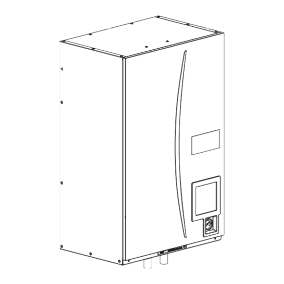
PART NAMES AND FUNCTIONS -
Page 8: Outlines And Dimensions
OUTLINES AND DIMENSIONS 5-1. Technical Drawings Unit: mm Hook Automatic air vent Front panel Earth leakage circuit breaker Back panel Terminal block support Main Controller Pressure relief valve G1/2 (242) - Page 9 5-2. Service access diagrams Service access Parameter Dimension (mm) Sufficient space MUST be left for the provision of discharge pipework as detailed in National and Local building regulations. The hydrobox must be located indoors and in a frost-free environment, for example in a utility room.
-
Page 10: Wiring Diagram
WIRING DIAGRAM 6-1. EHSC-MEC, EHSD-MEC, ERSC-MEC Indoor unit powered Indoor unit powered by independent source via outdoor unit To outdoor To outdoor Power supply unit ~/N 230V 50Hz unitConnect them using either way as shown below. Tool Tool CNPWM... -
Page 11
6-2. EHSC-VM2C, EHSC-VM2EC, EHSD-VM2C, ERSC-VM2C, ERSD-VM2C, EHPX-VM2C Indoor unit powered Indoor unit powered by independent source via outdoor unit To outdoor To outdoor Power supply Power supply unit unit
~/N 230V 50Hz to Booster heater Connect them using either way as shown below. -
Page 12
6-3. EHSC-VM6C, EHSC-VM6EC Indoor unit powered Indoor unit powered by independent source via outdoor unit To outdoor To outdoor Power supply Power supply unit unit
~/N 230V 50Hz to Booster heater Connect them using either way as shown below. ~/N 230V 50Hz Tool CNPWM... -
Page 13
6-4. EHSC-YM9C, EHSC-YM9EC, EHPX-YM9C Indoor unit powered Indoor unit powered by independent source via outdoor unit To outdoor To outdoor Power supply unit unit
~/N 230V 50Hz Power supply to Booster heater Connect them using either way as shown below. 3~ 400V 50Hz Tool Tool... -
Page 14
6-5. EHSC-TM9C Indoor unit powered Indoor unit powered by independent source via outdoor unit To outdoor Power supply To outdoor Power supply
unit ~/N 230V 50Hz unit to Booster heater Connect them using either way as shown below. 3~ 230V 50Hz Tool Tool... -
Page 15: Dip Switch Setting
6-6. DIP switch setting Located on the FTC printed circuit board are 5 sets of small white switches known as DIP switches. The DIP switch number is printed on the circuit board next to the relevant switches. The word ON is printed on the circuit board and on the DIP switch block itself. -
Page 16: Field Wiring
FIELD WIRING Breaker abbreviation Meaning ECB1 Earth leakage circuit breaker for booster heater Terminal block 1 Option 1: Hydrobox powered via outdoor unit <1 phase> Affix label A that is included with the manuals near each wiring diagram for hydrobox and outdoor units. Hydrobox Outdoor unit To control... - Page 17 Option2: Hydrobox powered by independent source If the hydrobox and outdoor units have separate power supplies, the following requirements MUST be carried out: • Change connector connections in hydrobox control and electrical box (see Figure 7-3). White Initial settings CN01 • Turn the outdoor unit DIP switch SW8-3 to ON. (Power supplied Hydrobox • Turn on the outdoor unit BEFORE the hydrobox. by outdoor unit) control board • Power by independent source is not available for particular models of outdoor unit model.
-
Page 18: Water System Diagram
WATER SYSTEM DIAGRAM *1 Refer to the following section [Local system]. EHS*- EHS*- EHSC- ERS*- ERSC- EHPX- Part name *M*C *M*EC VM2C *M*C - Page 19 Local system 1-zone temperature control Zone1 Zone1 2-zone temperature control 1-zone temperature control with boiler Zone1 Zone1 Zone2 2-zone temperature control with boiler 1-zone temperature control (2-zone valve ON/OFF control) Zone1 Zone1 Zone2 Zone2 1. Zone1 heat emitters (e.g. radiator, fan coil unit) (local supply) 10.
- Page 20 Filling the System (Primary Circuit) 1. Check all connections including factory fitted ones are tight. 2. Insulate pipe work between hydrobox and outdoor unit. 3. Thoroughly clean and flush, system of all debris. (Refer to 4.2 in the installation manual.) 4.
-
Page 21: Controls
CONTROLS 9-1. Main ControllerLetter Name Function Screen Screen in which all information is displayed Menu Access to system settings for initial set up and modifications. Back Return to previous menu. Confirm Used to select or save. (Enter key) Power/Holiday If system is switched off pressing once will turn system on. -
Page 22: General Operation
9-2. Setting the Main Controller After the power has been connected to the outdoor and hydrobox (See section 7) the initial system settings can be entered via the main controller. 1. Check all breakers and other safety devices are correctly installed and turn on power to the system. 2. -
Page 23
Initial Unrestricted access Main screen * Short press for 1 Zone system. Installer only Shaded items relate Information to DHW functions. These are only avail- Option Forced DHW ON ( )/OFF able if the system in- ON ( )/Prohibited ( )/Timer ( ) cludes a DHW tank. -
Page 24
Initial Unrestricted access Installer only Main screen Main Shaded items relate Menu menu to DHW functions. Manual operation These are only avail- Long Press Function settings able if the system in- Service cludes a DHW tank. Thermistor adjustment Password ON/OFF... -
Page 25: Service Menu
9-4. Service Menu The service menu provides functions for use by installer or service engineer. It is NOT intended the home owner alters settings within this menu. It is for this reason password protection is required to prevent unauthorised access to the service settings. The factory default password is "0000". -
Page 26
This function allows adjustments to be made to the thermistor readings from -10 – 10 °C in 0.5 °C intervals. THW1: Thermistor (Flow water temp.) THW2: Thermistor (Return water temp.) THW5: Thermistor (DHW tank water temp.)(Option) THW6: Thermistor (Zone1 flow temp.)(Option) THW7: Thermistor (Zone1 return temp.)(Option) THW8: Thermistor (Zone2 flow temp.)(Option) THW9: Thermistor (Zone2 return temp.)(Option) - Page 27 Mixing valve control 1. From the Auxiliary settings menu highlight Mixing valve control. 2. Press CONFIRM. 3. The Mixing valve control screen is displayed. 4. Use F1 and F2 buttons to set Running time between 10 to 240 seconds. The Running time equals to a period from full open of the valve (at a hot water mixing ratio of 100%) to full close (at a cold water mixing ratio of 100%).
-
Page 28
Heating operation This function allows operational setting of flow temperature range from the Ecodan and also the time interval at which the FTC collects and processes data for the auto adaptation mode. Menu subtitle Function Range Unit Default Flow temp. -
Page 29
1. General description End user can monitor accumulated*1 ‘Consumed electrical energy’ and ‘Delivered heat energy’ in each operation mode*2 on the main controller. *1 Monthly and Year to date *2 - DHW operation - Space heating - Space cooling Refer to the menu tree in “9-3. -
Page 30
Demand control(IN4) The selection of “OFF”, whilst a signal is being sent to IN4, forcefully stops all the heat source operations and the selection of “Boiler” stops operations of heat pump and electric heater and performs boiler operation. Outdoor thermostat (IN5) External input settings menu screen The selection of “Heater”, whilst a signal is being sent to IN5, performs... -
Page 31
This function shows the current installer/user entered settings. Abbreviation Explanation Abbreviation Explanation HWtemp DHW max temperature Z2 mode Operation mode HWdrop DHW temperature drop - HER (Heating room temperature) HWtime DHW max operation time - HE (Heating flow temperature) NO HW DHW mode restriction - HCC (Heating compensation curve) - Page 32 Resetting the password If you forget the password you entered, or have to service a unit somebody else installed, you can reset the password to the factory default of 0000. 1. From the main settings menu scroll down the functions until Service Menu is highlighted.
-
Page 33
Request Request content Range Unit code Error history 1 (latest) Displays error history. ("– –" is displays if no history is present.) Code Error history 2 (second to last) Displays error history. ("– –" is displays if no history is present.) —...
- Page 34 Indoor unit switch setting display (Request code: 162 to 166) 0: OFF 1: ON 0: OFF 1: ON SW1, SW2, SW3, SW4, SW5 SW1, SW2, SW3, SW4, SW5 Display Display 00 00 00 40 00 01 00 41 00 02 00 42 00 03 00 43...
- Page 35 Indoor unit switch setting display (Request code: 162 to 166) 0: OFF 1: ON 0: OFF 1: ON SW1, SW2, SW3, SW4, SW5 SW1, SW2, SW3, SW4, SW5 Display Display 00 80 00 C0 00 81 00 C1 00 82 00 C2 00 83 00 C3...
- Page 36 Output signal display (Request code: 175/553) Please refer to Table 2 on relevant wiring diagram whilst using the following. 0: OFF 1: ON 0: OFF 1: ON Display Display xx 40 xx 00 xx 41 xx 01 xx 42 xx 02 xx 43 xx 03 xx 44...
- Page 37 Output signal display (Request code: 175/553) Please refer to Table 2 on relevant wiring diagram whilst using the following. 0: OFF 1: ON 0: OFF 1: ON Display Display xx C0 xx 80 xx C1 xx 81 xx C2 xx 82 xx C3 xx 83 xx C4...
- Page 38 Display Output signal display (Request code: 175/553) 40 xx Please refer to Table 2 on relevant wiring diagram whilst using the following. 41 xx 42 xx 0: OFF 1: ON 43 xx Display 44 xx 45 xx 00 xx 46 xx 01 xx 47 xx 02 xx...
- Page 39 Input signal display (Request code: 176/554) Please refer to Table 1 on relevant wiring diagram whilst using the following. 0: OFF (open) 1: ON (short) 0: OFF (open) 1: ON (short) Display Display 00 00 00 40 00 01 00 41 00 02 00 42 00 03...
- Page 40 Indoor unit only operation Indoor unit only operation In indoor unit only operation, an operation without connecting outdoor unit is possible. When in Indoor unit only operation the main control has control functions. Indoor unit Necessary Heat pump Not necessary
... Page 41: Troubleshooting
TROUBLESHOOTING 10-1. TroubleshootingPresent and past Error codes are logged and displayed on the main controller or control board of the outdoor unit. Please refer to the table below and subsequent explanations to diagnose and remedy typical problems that may occur in the field. Unit Condition Error Code Action... - Page 42 10-4. Self diagnosis and action Check if DIP SW is set correctly. (Refer to Section 6-6.) Error code Title and display conditions Possible Cause Diagnosis and action Circulation water temperature overheat Insufficient system head Refer to table in section 10-6. to determine if protection system pump meets requirements.
- Page 43 Error code Title and display conditions Possible Cause Diagnosis and action P1/P2/L5/LD Indoor unit temperature thermistor failure Connector/terminal wire has become Visually check the terminals and connec- * The thermistors subject to failure can be detached or loose wiring. tions and reattachas appropriate. checked in “Request code: 567”...
- Page 44 Error code Title and display conditions Possible Cause Diagnosis and action Heating operation error THW1 has become detached from its Visually inspect location and reattach as * “3” is displayed in “Request code: 567” in “Run- holder. necessary. ning information”.
... - Page 45 Error code Title and display conditions Possible Cause Diagnosis and action Low primary circuit (Zone2 side) flow rate Insufficient system head If more head required either add an pump of the same size or replace existing pump. detected by flow switch * “3” is displayed in “Request code: 569” in “Run- Reduced flow in primary water circuit Check circulation pump (See 10-6.
- Page 46 Error code Title and display conditions Possible Cause Diagnosis and action
THW2 detects a temperature ≤15ºC and TH2 1. Reduced water flow 1., 2. Check water piping. detects a temperature ≤−16ºC for consecutive 10 • Clogged filter seconds. •... - Page 47 Error code Title and display conditions Possible Cause Diagnosis and action E1/E2 Main controller control board failure 1. Fault with the main controller circuit 1. Replace main controller circuit board. board Error code E1 displayed if main controller can not access it's non volatile (non power dependent) memory.
- Page 48 10-5. Troubleshooting by inferior phenomena Fault symptom Possible cause Explanation - Solution Main controller display 1. There is no power supply to main 1. Check LED2 on FTC. (See 6. WIRING DIAGRAM) is blank. controller. (i) When LED2 is lit. Check for damage or contact failure of the main controller wiring.
- Page 49 Contact your Mitsubishi Electric dealer. 7. Immersion heater cut-out tripped. 7. Check immersion heater thermostat and press reset button, located on im- mersion heater boss, if safe.
- Page 50 Contact your Mitsubishi Electric dealer. 5. Immersion heater cut-out has been triggered. 5. Check immersion heater thermostat and press reset button if safe. If the heater kept running with no water inside, this may have resulted in failure, so replace it with a new one.
- Page 51 Fault symptom Possible cause Explanation - Solution In 2-zone tempera- When Zone1 and Zone2 are both in heating Normal action no action necessary. ture control, only mode, the hot water temperature in Zone2 Zone2 does not does not exceed that in Zone1. reach the set tem- Faulty wiring of motorized mixing valve Refer to "5.3 Wiring for 2-zone temperature control"...
Page 52: Annual Maintenance
Annual Maintenance It is essential that the hydrobox is serviced at least once a year by a qualified individual any spare parts required MUST be purchased from Mitsubishi Electric (safety matter). NEVER bypass safety devices or operate the unit without them being fully operational.- Page 53 10-6. Checking Component Parts' Function Part Name Check Points
EHSC series 80.0 Speed 5 (Default) 70.0 BROWN Speed 4 PWM input signal Signal cable Speed 3 BLUE 60.0 Signal ref. Speed 2 BLACK 50.0 Speed 1 Feedback signal 40.0 BROWN... - Page 54 Part Name Check Points Earth leakage circuit breaker for heater If a short circuit occurs on the booster heater, immersion heater, or each power line, a short-circuit breaker will trip and power source will be blocked. Eliminate the causes of short circuit and then turn on the breaker again. Relay for heater When the applied voltage is not 230V AC across the terminals A1-A2, check the terminals A1 A2...
- Page 55 Part Name Check Points Thermistors Disconnect the connector then measure the resistance with a tester. (At ambient temperatures of 10 - 30°C.) Thermistor Normal Abnormal THW1 THW2 THW5 4.3 - 9.5 kΩ Open or short THW6 THW7 THW8 THW9 THWB1 40 - 100 kΩ...
- Page 56
• Room temperature thermistor (TH1) • Liquid refrigerant temperature thermistor (TH2) • Flow water temperature thermistor (THW1) • Return water temperature thermistor (THW2) • DHW tank temperature thermistor (THW5) • Zone 1 flow water temperature thermistor (THW6) •... - Page 57 10-7. Test point diagram FTC (Controller board) CNP1/OUT1 (TBO.1 1-2) Water circulation pump1 (230V AC) OUT2 (TBO.1 3-4) Water circulation pump2 (Local supply) (230V AC) CN01 OUT3 (TBO.1 5-6) Power supply Water circulation pump3 (230V AC) (Local supply) (230V AC) CNP4/OUT14 Water circulation pump4 (230V AC)
Page 58: Disassembly Procedure
DISASSEMBLY PROCEDURE● Prepare the proper tools. ● Prepare the proper protectors. ● Provide adequate ventilation. ● After stopping the operation of the hydrobox and outdoor unit, turn off the power-supply breaker and remove the power plug. - Page 59 PHOTOS DISASSEMBLY PROCEDURE 3. How to remove the electrical parts Photo 3-1 Control box fixing screws (Steps (1) through (3) are applied to all the following parts.) (1) Remove the front panel. (Refer to Procedure 1). (2) Remove the 3 screws holding the control box. (Photo 3-1) (3) Slightly lift and pull out the control box.
- Page 60 PHOTOS DISASSEMBLY PROCEDURE 4. How to swing the control box to the front Photo 4-1 (1) Remove the front panel. (Refer to Procedure 1.) Earth cable Side panel (2) Remove the screw from the control box bracket (R) and 2 screws from the control box bracket (L).
- Page 61 DISASSEMBLY PROCEDURE PHOTOS 5. How to remove water pump/ pump valve Photo 5-1 Water pump E*S* series Cable connector (CNP1) CNPWM clamp
Earth cable connector Close the pump valve (OFF) before removing the water pump, Lead and open the valves (ON) after reinstalling the water pump. wire (1) Remove the front panel. - Page 62 DISASSEMBLY PROCEDURE PHOTOS 5. How to remove water pump/ pump valve(continued) Photo 5-5(EHPX series) EHPX series
Gasket Terminal Gasket Close the pump valve and strainer valve (OFF) before (G1") (G1") (G1") (G1") removing the water pump, and open the valves (ON) after reinstalling the water pump. - Page 63 DISASSEMBLY PROCEDURE PHOTOS 6. How to remove the flow sensor Photo 6-1 (1) Remove the front panel. (Refer to Procedure 1.) (2) Disconnect the CN1A connector on the controller board. (Photo 6-1) (3) Release the flow sensor lead wire from the cable clamp, the 2 cable straps, the coated clamp and feed the lead wire out the control box without putting strain on the CN1A...
- Page 64 DISASSEMBLY PROCEDURE PHOTOS Photo 7-1 7. How to remove the booster heater (1) Remove the front panel. (Refer to Procedure 1.) Booster heater Control box (2) Disconnect the booster heater lead wires from the CNBHT connector (CNBHT) connector on the controller board and from the BHC1 (Lead wire No.1, No.2 and No.3) and BHC2 (Lead wire No.4, No.
- Page 65 DISASSEMBLY PROCEDURE PHOTOS 7. How to remove the booster heater (continued) EHPX series> < (4) Detach the quick connection 1 and 2. (Photo 7-4) • When reinstalling the quick connections, use new O-rings. • Refer to page 77 for how to attach and detach the quick connection.
- Page 66 DISASSEMBLY PROCEDURE PHOTOS 8. How to remove the plate heat exchanger Photo 8-1 CNPWM Water pump (1) Pump down the refrigerant circuit and close the stop connector connector (CNP1) valve on the outdoor unit. (Refer to "12. Supplementary Earth cable information".) (2) Remove the front panel.
- Page 67 DISASSEMBLY PROCEDURE PHOTOS 8. How to remove the plate heat exchanger(continued) Photo 8-3(ERSC series)
(7) Close the strainer valve and remove the G1" nut on the water outlet side of the strainer valve using two spanners: one to hold the strainer valve and the other to turn the G1"... - Page 68 DISASSEMBLY PROCEDURE PHOTOS
Photo 8-6(EHSC series) Procedure (1) to (6) is the same as . (7) Remove the G1" nut on the water inlet side of the strainer valve using two spanners: one to hold the strainer valve and the other to turn the G1" nut. (Photo 8-5) •... - Page 69 DISASSEMBLY PROCEDURE PHOTOS 8. How to remove the plate heat exchanger(continued) Refer to the previous page for step (1) to (5). (Skip (4).)
- Page 70 DISASSEMBLY PROCEDURE PHOTOS 8. How to remove the plate heat exchanger(continued) Photo 8-8(E*SD series)
- Page 71 DISASSEMBLY PROCEDURE PHOTOS 9. How to remove the strainer Photo 9-1(ERS* series)
- Page 72 DISASSEMBLY PROCEDURE PHOTOS 9. How to remove the strainer(continued) Photo 9-6(EHPX series)
(1) Remove the front panel. (Refer to Procedure 1.) Strainer Strainer Nut (G1") valve L joint valve stay (2) Swing the control box to the front. (Refer to Procedure 4.) (3) Close the strainer valve (OFF). - Page 73 DISASSEMBLY PROCEDURE PHOTOS 10. How to remove the manometer / pressure relief valve / air Photo 10-1 vent (automatic) Claw Screw (1) Remove the front panel. (Refer to Procedure 1.) (2) Swing the control box to the front. (Refer to Procedure 4.)
... - Page 74 DISASSEMBLY PROCEDURE PHOTOS 10. How to remove the manometer / pressure relief valve / air Photo 10-5 vent (automatic) (Continued) Expansion vessel Air vent
(1) Remove the air vent with a flare joint using two spanners: one to hold the flare joint and the other to turn the flare nut. - Page 75 DISASSEMBLY PROCEDURE PHOTOS Photo 13-1 13. How to remove the thermistor
(TH2) / thermistor Earth leakage breakers (ECB1) (THW1, THW2) (1) Remove the front panel. (Refer to Procedure 1.) (2) Remove the control box cover. (Refer to Procedure 3.) (3) Disconnect the following connectors on the control board. - Page 76 DISASSEMBLY PROCEDURE PHOTOS Photo 14-1 14. How to remove the drain pan (ERS*series) (1) Remove the front panel. Strainer valve stay Strainer valve (2) Disconnect all the field piping. (3) Remove the saddle band and the rubber tube by removing the 2 screws. Then remove the 2 screws fixing the strainer valve stay.
- Page 77 PHOTOS & ILLUSTRATION DISASSEMBLY PROCEDURE Photo 15-1 15. How to detach and attach the quick joint Refer to the following steps when detaching and attaching the quick connection. (1) Remove the clip. (Photos 15-1 and 15-2) (2) Separate the connected parts to remove the O-ring. (Photo 15-3) •...
- Page 78 Notes on replacing the parts Replacement of the parts listed below requires the following procedure. After the parts are removed, eliminate loctite on threads by applying loctite remover, apply new loctite, and then install and tighten the parts to the specified tightening torques below.
Page 79: Supplementary Information
SUPPLEMENTARY INFORMATION 12-1. Refrigerant collecting (pumpdown) for split model systems only Refer to “Refrigerant collection” in the outdoor unit installation manual or service manual. 12-2. Back-up operation of boiler Heating operation is backed up by boiler. For more details, refer to the installation manual of PAC-TH011HT-E.Page 80: Service And Maintenance
SERVICE AND MAINTENANCE The main controller settings changed from the default settings are reset by replacing the controller board. To facilitate reselecting settings on the main controller, it is recommended to write down the changes in the sheet below before replacement. 13-1.- Page 81 Engineers Forms (2/2) Commissioning/Field settings record sheet (continued from the previous page) Default Field Main controller screen Parameters Notes setting setting Service menu Pump speed Pump speed(1 - 5) Heat source setting Standard/Heater/Boiler/Hybrid *7 Standard Operation Heating operation Flow temp.range Min.temp.(25 - 45°C) 30°C settings...
- Page 82 13-2. Annual Maintenance Log Book Contractor name Engineer name Site name Site number Hydrobox maintenance record sheet Warranty number Model number Serial number Mechanical Frequency Notes Isolate and drain hydrobox, remove mesh from internal strainer clean and replace. Open the pressure relief valve, check for unrestricted discharge to the tundish and that the valve reseats correctly.
- Page 83 OCH571...
- Page 84 HEAD OFFICE : TOKYO BLDG., 2-7-3, MARUNOUCHI, CHIYODA-KU, TOKYO 100-8310, JAPAN Copyright 2014 MITSUBISHI ELECTRIC CORPORATION Distributed in Oct. 2014 No. OCH571 New publication, effective Oct. 2014 Made in Japan Specifications are subject to change without notice.
Table of Contents