Honeywell T775A User Manual
Remote temperature controller
Hide thumbs
Also See for T775A:
- Installation instructions manual (37 pages) ,
- Product data (16 pages) ,
- Instruction instructions (36 pages)
Table of Contents
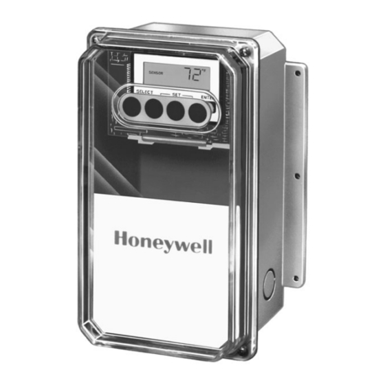
Remote Temperature Controller
The T775 family of Electronic Remote Tem-
perature Controllers provide on-off temperature
control for ducts, tanks, chillers, heating and re-
frigeration units, and other applications where
electronic accuracy in addition to remote sensing
is desired.
In addition, certain models of the T775 family
of controllers provide on-off temperature control
of heating, cooling, and ventilating systems in agri-
cultural confinement buildings, storage areas and
heavy industrial applications.
T775A models provide staged on-off control with
one temperature input and one to four relay output
stages.
T775B models provide staged on-off control with
two temperature inputs and two to four relay output
stages.
T775C models provide staged on-off control with
one temperature input and four relay output stages.
T775D models provide staged on-off control with
two temperature inputs and four relay output stages.
T775C,D models meet National Electrical Code
(Article 547) requirements for animal confinement
buildings.
Setpoint temperature range is -40° to +220° F (-40°
to +104°C).
Ambient temperature range is -30° to +140°F for
one and two stage models and -30° to +125°F for
three and four stage models.
Linear platinum temperature sensor with T775A,B.
Water-tight linear platinum temperature sensor with
T775C,D.
G.R. • 12-94 • ©Honeywell Inc. 1994
T775A,B,C,D
T775A,B
Adjustable temperature range and differential.
LCD indication for mode and output status.
Keypad provides ease of programming and operation.
Accuracy is within +/- 1°F (at nominal operating
ambient temperature of 77°F and voltage input).
Stage(s) independently programmed for heating or
cooling.
24/120/240 Vac input voltage.
Spdt relay outputs.
IMPORTANT: The T775 is an operating control, not a
limit or safety control. If used in applications requir-
ing safety or limit controls, a separate safety or limit
control device should be used in conjunction with the
T775.
CONTENTS
Specifications ................................................. 2
Ordering Information ..................................... 2
Installation ..................................................... 5
Description/Operation ................................... 8
Checkout ....................................................... 11
1
T775C,D
63-2489
63-2489
Table of Contents

Related Manuals for Honeywell T775A


Summary of Contents for Honeywell T775A
- Page 1 T775A,B T775C,D T775A models provide staged on-off control with Adjustable temperature range and differential. one temperature input and one to four relay output LCD indication for mode and output status. stages.
-
Page 2: Specifications
If you have additional questions, need further information, or would like to comment on our products or services, please write or phone: 1. Your local Honeywell Home and Building Control Sales Office (check the white pages of your phone directory. - Page 3 125 VA pilot duty at 120/240 Vac. 10A at 24 Vac (resistive). SENSOR: Positive coefficient platinum type, 4.8 ohms/ °F, Fig. 1—Approximate dimensions of T775A,B in in. (mm). 1000 ft maximum distance between sensor and solid state controller (requires calibration over 400 ft). To maintain NEMA 4X rating, use environmental proof cable and sensor.
- Page 4 240V KNOCKOUT B KNOCKOUT C OUTPUT 3 OUTPUT 4 RELAY OUTPUT STAGES NOTE: T775A TERMINAL BLOCK CONTAINS ONLY (MAXIMUM OF FOUR STAGES) TERMINALS 1-6 AND HAS NO DIP SWITCHES FOR SENSOR SELECTION M7423 Fig. 4—Feature locations for T775C,D. LCD TEMPERATURE C \ F °F/°C SELECTION...
- Page 5 Use controller dimensions in OUTPUT 2 OUTPUT 1 120V Fig. 1 (T775A,B) or Fig. 2 (T775C,D) as a guide. 240V SENSOR LOCATION The 193987GA Sensor can be located up to 1000 feet (304 meters) from the T775 using standard AWG 18/2...
- Page 6 T775A,B,C,D INSTALLATION Fig. 6—Sensor mounted on wall. Fig. 7—Parallel-series wiring of sensors. T7047C1090 BLACK LEAD WALLMOUNT SENSOR CASE (OPTIONAL) 193987GA SENSOR SENSORS LEADWIRES TO T775 SCREW TERMINAL SCREW TERMINAL WHITE LEAD TO T775 CONNECTIONS 1 AND 2 (SENSOR A) OR 7 AND 8 (SENSOR B)
- Page 7 T775A,B,C,D INSTALLATION When wiring the input power, only one source of power cooling operating modes. When in cooling mode, the load can be applied to the T775 (for example, 24 Vac or 120 Vac will be turned off at setpoint plus the differential. When in or 240 Vac).
- Page 8 Each stage of the T775A,B,C, and D has its EXAMPLE: Using a device with one input and one relay own independent setpoint that can be configured to operate output, the corresponding load would be energized at the in either the heating or cooling mode.
- Page 9 T775A,B,C,D DESCRIPTION/OPERATION Cooling Mode: KEYPAD PROGRAMMING AND DISPLAY • Stage One: Energized at 70°F. The T775 utilizes a Liquid Crystal Display (LCD) for interactive prompting during programming and display of The T775B,D have dual sensor inputs and allow two sensed and assigned setpoint and differential values. User separate controllers to exist within one enclosure.
- Page 10 Make sure that the sensors are To maintain temperature accuracy, sensor wires should connected properly. For T775A,C all loads will be de- be 18 AWG two-conductor. If the length of the sensor wire energized when this error message is flashing.
- Page 11 T775A,B,C,D CHECKOUT Checkout After the controller is installed and wired, apply power. 7. Verify which loads are energized by using the Check- Make initial adjustments and desired settings. out Table. As shown in the example, the display will indi- 1. As shown in Fig. 8, record the sensed temperatures for cate, in the lower right corner, which stages are energized.
- Page 12 T775A,B,C,D CHECKOUT Fig. 10—Checkout Table and checkout example with Sensor A = 68°F and Sensor B = 73°F. CHECKOUT EXAMPLE WITH SENSOR A = 68° AND SENSOR B = 73° LOAD 1 LOAD 2 LOAD 3 LOAD 4 HEAT OR COOL...
- Page 13 T775A,B,C,D CHECKOUT Fig. 11—Two-stage control, 24 Vac input, 24 Vac load. COOL MODE TEMPERATURE C \ F FALL DIP SWITCHES RELAY 1 AND 2 FOR SENSOR ENERGIZED SELECTION. PRESENT ON T775B, D ONLY DIFFERENTIAL SELECT ENTER SENSOR B to pins 7 AND 8...
- Page 14 T775A,B,C,D CHECKOUT Fig. 12—Two-stage control, 120 or 240 Vac input; 120 or 240 Vac load. 120 VAC INPUT; 120 VAC LOADS C \ F DIP SWITCHES FOR SENSOR SELECTION. PRESENT ON T775B, D ONLY SENSOR B SELECT ENTER to pins 7 AND 8...
- Page 15 T775A,B,C,D CHECKOUT Fig. 13—Four-stage control, 24 Vac input; 24 Vac load. C \ F DIP SWITCHES FOR SENSOR SELECTION. PRESENT ON SENSOR B SELECT ENTER T775B,D ONLY to pins 7 AND 8 SA SB for T775B,D SENSOR A SENSOR SENSOR...
- Page 16 LOAD 2 LOAD 1 M7424 Home and Building Control Home and Building Control Helping You Control Your World Honeywell Inc. Honeywell Limited—Honeywell Limitée 1985 Douglas Drive North 740 Ellesmere Road Golden Valley, MN 55422 Scarborough, Ontario M1P 2V9 63-2489 Printed in U.S.A.