Honeywell T775B Series Instruction Instructions
Hide thumbs
Also See for T775B Series:
- Installation instructions manual (37 pages) ,
- User manual (17 pages) ,
- Product data (16 pages)
Quick Links
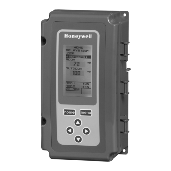
T775A/B/M Series 2000 Electronic
Stand-Alone Controllers
Controller
a
Model
Description
T775A2009 Standard
T775B2016 Standard
T775B2024 Standard
T775B2032 Standard
T775B2040 Standard
T775M2006 Modulating
T775M2014 Modulating
T775M2022 Modulating
T775M2030 Modulating
T775M2048 Modulating
a
All models include a digital input for use with the disable or setback option.
b
The modulating (analog) outputs are 4-20 mA, 0-10 Vdc, 2-10 Vdc, or Series 90 selectable.
c
Each floating output eliminates two SPDT relays.
d
These models can support a high/low modulating limit at Sensor B for temperature control at Sensor A.
Table 1. T775A/B/M Controller Configurations.
Replaces
T775A1001
N/A
T775C1009 T775D1008
T775A1019 T775B1000
T775A1027 T775A1035
T775B1018 T775B1026
T775B1042
N/A
T775G1005 T775G1013
T775G1021 T775G1039
N/A
T775E1114 T775F1022
T775F1055 T775F1089
T775E1015 T775E1023
T775E1056 T775E1064
T775E1098
E4436
PRODUCT DESCRIPTION
The T775 electronic stand-alone controllers are the next
generation of commercial and agricultural controls
capable of remote sensing of temperature and providing
switched and/or proportional outputs to various types of
loads.
Five models have analog (modulating) outputs for
actuator and motor control, and NEMA-4 weatherproof
enclosures are available for wet environments.
IMPORTANT
Each T775A/B/M controller is an operating
control, not a limit or safety control. If used in
applications requiring safety or limit controls, a
separate safety or limit control device is
required.
Analog
SPDT
(Mod)
Floating
Relay
b
Outputs
Outputs
Outputs
1
None
2
None
4
None
2
None
4
None
None
2
4
2
2
2
4
2
2
2
INSTALLATION INSTRUCTIONS
Nbr of
Sensor
Sensors
c
Inputs
Included Enclosure
None
1
1
1
2
1
2
2
1
1
2
1
2
2
1
N/A
2
1
N/A
1
d
2
N/A
1
d
2
N/A
1
d
2
N/A
1
d
2
NEMA 1
NEMA 4X
NEMA 4X
NEMA 1
NEMA 1
NEMA 1
NEMA 4X
NEMA 4X
NEMA 1
NEMA 1
62-0254-03

Related Manuals for Honeywell T775B Series


Summary of Contents for Honeywell T775B Series
- Page 1 T775A/B/M Series 2000 Electronic Stand-Alone Controllers INSTALLATION INSTRUCTIONS PRODUCT DESCRIPTION The T775 electronic stand-alone controllers are the next generation of commercial and agricultural controls capable of remote sensing of temperature and providing switched and/or proportional outputs to various types of loads.
- Page 2 T775A/B/M SERIES 2000 CONTROLLER PRODUCT DESCRIPTION Temperature Sensors Accessories The controller accepts 1,097 Ohms PTC at 77°F (25°C): • 107324A – Bulb Holder, duct insertion • 50021579-001 – Standard sensor (included with all • 107408 – Heat Conductive Compound, 4 ounce models except NEMA 4X models) •...
- Page 3 BEFORE INSTALLATION T775A/B/M SERIES 2000 CONTROLLER BEFORE INSTALLATION The controller may be mounted in any orientation. However, mounting in the orientation shown in Fig. 1 permits proper viewing of the LCD display and use of the Review the “Specifications” on page 35 before keypad.
- Page 4 T775A/B/M SERIES 2000 CONTROLLER WIRING Wiring Connections Access NOTE: Each T775 controller must be wired to its own sensor(s). However, a benefit of the T775 To access the wiring connections, remove the two screws controller’s accuracy is that there is no more on the left side of the enclosure and gently swing open the than a 2°F differential between any two T775 top.
- Page 5 WIRING T775A/B/M SERIES 2000 CONTROLLER Controller Wiring See Fig. 7 on page 6 for locating the appropriate power input, remote sensors input, low voltage, contact closure, and load output terminals. WARNING Access to the terminals can be gained through standard conduit knockouts (A through E in Fig.
- Page 6 T775A/B/M SERIES 2000 CONTROLLER WIRING APPLICATIONS (EXAMPLES) Controller Wiring Details Table 2. Description of Wiring Terminal Connections. (Continued) The wiring connection terminals are shown in Fig. 7 and are described in Table 2. Connection Terminal Label Description Input See Fig. 8 – Fig. 20 beginning on page 6 for typical Digital Input (dry T775A/B/M wiring applications.
- Page 7 WIRING APPLICATIONS (EXAMPLES) T775A/B/M SERIES 2000 CONTROLLER SENSOR A SENSOR A (HOT) 24 VAC 120V LOAD LOAD LOAD LOAD LOAD LOAD 1 LOAD 4 LOAD M24476A 1 FOR 240 VAC LOAD, CONNECT TO 240 TERMINAL. M24478A Fig. 9. Wiring for four-stage control – 24 Vac input Fig.
- Page 8 POTENTIOMETER (H205 OR H705) M24482 MODUTROL MOTOR (Q209) Fig. 14. Wiring for Digital Input (dry contact). W R B T1 T2 B HONEYWELL MODUTROL MOTOR WITH 4-20 mA MODULATING INPUT POWER – + T1 T2 OUTPUT – MODULATING OUTPUT POWER –...
- Page 9 WIRING APPLICATIONS (EXAMPLES) T775A/B/M SERIES 2000 CONTROLLER M9184 OR M9185 (HOT) MODUTROL MOTOR – M9184 OR M9185 MODUTROL MOTOR – M9184 OR M9185 MODUTROL MOTOR MODULATING OUTPUT TERMINAL (MOD 1) POWER SUPPLY. PROVIDE DISCONNECT MEANS AND OVERLOAD PROTECTION AS REQUIRED. USE A 1300 OHM RESISTOR FOR TWO MOTORS, 910 OHM RESISTOR FOR THREE MOTORS.
- Page 10 T775A/B/M SERIES 2000 CONTROLLER CHECKOUT CHECKOUT Table 3. Temperature Sensor Calibration for Resistance Loss due to Wire Length. Inspect all wiring connections at the controller terminals, Temperature Offset in and verify compliance with the installation wiring °F (Foot) diagrams. Rating mΩ/ft 200 ft 500 ft...
- Page 11 INTERFACE OVERVIEW T775A/B/M SERIES 2000 CONTROLLER INTERFACE OVERVIEW Menu Button • Pressing the MENU button always displays the Program menu. If you are in Setup mode, you exit The T775A/B/M controllers use an LCD panel and setup and return to the Program menu. 6-button keypad to provide status information and permit •...
- Page 12 T775A/B/M SERIES 2000 CONTROLLER INTERFACE OVERVIEW Accessing the Menus HOME Menus are used for programming, scheduling, viewing the RELAYS 1 2 3 4 summary settings, and setup of advanced options. SETUP SENSORS SENSORS SENSOR A Programming, Scheduling, and Summary Menus OUTPUTS EXIT To access these menus from the home screen, press the...
- Page 13 1. PROGRAMMING T775A/B/M SERIES 2000 CONTROLLER 1. PROGRAMMING Setpoint High Limit You can set a single irreversible setpoint high limit maximum value, which is applied to all outputs. The controller must be programmed before being placed into service. Adjust the setpoint (at any output) to the desired maximum setpoint.
- Page 14 T775A/B/M SERIES 2000 CONTROLLER 1. PROGRAMMING Programming the T775A/B/M Controller When programming is complete, you may continue with “3. Scheduling” on page 30 or, for advanced options, continue with “2. Setup (Advanced Options)” on page 17. To program the controller, perform the following procedures in the order listed: 1.
- Page 15 1. PROGRAMMING T775A/B/M SERIES 2000 CONTROLLER MENU 1.2.2. DIFFERENTIAL or THROTTLING RANGE PROGRAM PROGRAM RELAY 1 RELAY 1 Differential is used for Relay outputs and Throttling Range DIFFRNTL DIFFRNTL is used for Modulating outputs. 1. From the menu, use the buttons to high- light THROT RNG or DIFFERNTL.
- Page 16 T775A/B/M SERIES 2000 CONTROLLER 1. PROGRAMMING MENU 1.2.5. SETBACK PROGRAM PROGRAM RELAY 1 RELAY 1 The Setback temperature option displays if scheduling is SETBACK SETBACK enabled (see Fig. 55 on page 24) or the DI Option is set to Setback. (see Fig. 57 on page 25). This is the desired setpoint temperature that you want to use during setback mode for this output.
- Page 17 2. SETUP (ADVANCED OPTIONS) T775A/B/M SERIES 2000 CONTROLLER 2. SETUP (ADVANCED OPTIONS) Setup provides the ability to change the factory default Once in Setup mode, you use the — settings for the temperature sensors and outputs, to • Left arrow button( ) to scroll backward through the enable/disable reset control, and to enable/disable Setup menus scheduling.
- Page 18 T775A/B/M SERIES 2000 CONTROLLER 2. SETUP (ADVANCED OPTIONS) 2.2.2. SENSOR A SETUP SETUP SENSORS SENSORS SENSOR A 1. From the Sensors menu, highlight SENSOR A. SENSOR A 2. Press the button to display the Sensor A selec- UNITS tions. CALIBRATE LABEL EXIT M24502...
- Page 19 2. SETUP (ADVANCED OPTIONS) T775A/B/M SERIES 2000 CONTROLLER 2.2.2.4. Exit Sensor A Setup SETUP SENSORS Press the button to exit Sensor A selections and return SENSOR A to the Sensors menu. UNITS CALIBRATE Use the buttons to highlight EXIT and press the LABEL EXIT button.
- Page 20 T775A/B/M SERIES 2000 CONTROLLER 2. SETUP (ADVANCED OPTIONS) SETUP SETUP 2.2.4. LIMIT (Sensor B only) SENSORS SENSORS SENSOR B SENSOR B For the T775M2030 and T775M2048 models only, the LIMIT LIMIT LIMIT item displays on the Sensor B menu. DISABLE HI LIMIT NOTE: The LIMIT option acts only on Modulating LOW LIMIT...
- Page 21 2. SETUP (ADVANCED OPTIONS) T775A/B/M SERIES 2000 CONTROLLER 2.2.4.2. THROTTLING RANGE (Sensor B only) SETUP SETUP SENSORS SENSORS The throttling range for the modulating high or low limit SENSOR B SENSOR B positions the setpoint at the end of the throttling range. UNITS For example, with a high (Heat) limit at Sensor B of 200°F CALIBRATE...
- Page 22 T775A/B/M SERIES 2000 CONTROLLER 2. SETUP (ADVANCED OPTIONS) SETUP SETUP 2.3.1.1. TYPE (of output signal) OUTPUTS OUTPUTS MOD 1 MOD 1 TYPE 1. From the Mod menu, use the buttons to TYPE highlight TYPE. 4 - 20 mA 0-10 V 2.
- Page 23 2. SETUP (ADVANCED OPTIONS) T775A/B/M SERIES 2000 CONTROLLER SETUP SETUP 2.3.1.4. DERIVATIVE OUTPUTS OUTPUTS MOD 1 MOD 1 The Derivative default value is factory set to zero (no DERIVATIV DERIVATIV derivative control). It is strongly recommended that the derivative remain at zero (0) unless you have a very good reason to adjust it.
- Page 24 T775A/B/M SERIES 2000 CONTROLLER 2. SETUP (ADVANCED OPTIONS) 2.3.2. NBR OF RELAYS SETUP SETUP OUTPUTS OUTPUTS # RELAYS # RELAYS 1. From the Outputs menu, use the buttons to highlight # RELAYS. 2. Press the button to display the number of relays. 3.
- Page 25 2. SETUP (ADVANCED OPTIONS) T775A/B/M SERIES 2000 CONTROLLER SETUP SETUP 2.3.3.2. MIN OFF (minimum off time for all relays) OUTPUTS OUTPUTS OPTIONS OPTIONS This is the minimum number of seconds of “off time” for MIN OFF MIN OFF all relays. 1.
- Page 26 T775A/B/M SERIES 2000 CONTROLLER 2. SETUP (ADVANCED OPTIONS) 2.3.3.5. Exit Options Setup SETUP OUTPUTS Press the button (or highlight EXIT and press the OPTIONS button) to exit and return to the Outputs menu. USE SCHED MIN OFF Continue with “2.3.4. Setting up the Relays” DI OPTION SHOW RT EXIT...
- Page 27 2. SETUP (ADVANCED OPTIONS) T775A/B/M SERIES 2000 CONTROLLER 2.3.4.1.1. Floating Relay Menu SETUP SETUP OUTPUTS OUTPUTS The Floating option is only available on the T775B2016, FLOAT 1 FLOAT 1 T775B2024, T775B2032, and T775B2040 models. TYPE ACTUATOR When Relay 1 or Relay 3 is setup as floating, relays are INTEGRAL DERIVATIV paired and the Float 1 or Float 2 menu displays with the...
- Page 28 T775A/B/M SERIES 2000 CONTROLLER 2. SETUP (ADVANCED OPTIONS) SETUP SETUP 2.3.4.1.1.3. DERIVATIVE (modulating/floating relay only) OUTPUTS OUTPUTS FLOAT 1 FLOAT 1 The Derivative option displays only on the T775B2016, DERIVATIV DERIVATIV T775B2024, T775B2032, and T775B2040 models when the Type option = Floating. 1.
- Page 29 2. SETUP (ADVANCED OPTIONS) T775A/B/M SERIES 2000 CONTROLLER 2.4. EXIT Setup Mode SETUP OUTPUTS Press the button to exit the selected relay set up and RELAY 1 return to the Outputs menu. RESET SCHEDULE To setup the next relay output go to “2.3.4. Setting up the RESET RT EXIT Relays”...
- Page 30 T775A/B/M SERIES 2000 CONTROLLER 3. SCHEDULING 3. SCHEDULING Scheduling provides the ability to set daily temperature NOTES: settings for up to two events per day. Typically, these are If you press the HOME button or there is no the daytime (setpoint) and the nighttime (setback) keypad activity for four minutes, you exit settings.
- Page 31 3. SCHEDULING T775A/B/M SERIES 2000 CONTROLLER MAIN MAIN 3.2.1. SET TIME SCHEDULE SCHEDULE OPTIONS OPTIONS Setting the system time is required to enable the SET TIME SET TIME controller to follow daylight saving time. IMPORTANT Set the Date before setting the Time. See “3.2.2.
- Page 32 T775A/B/M SERIES 2000 CONTROLLER 3. SCHEDULING 3.3. Setting Individual Schedules MENU MENU SCHEDULE SCHEDULE As shown in the Schedule menu (Fig. 69 on page 30), MON-FRI MON-FRI schedules can be set for the following time periods: E1 SETPT • Monday through Friday E1 TIME •...
- Page 33 3. SCHEDULING T775A/B/M SERIES 2000 CONTROLLER MAIN MAIN 3.3.2. E1 TIME (time for event 1) SCHEDULE SCHEDULE MON-FRI MON-FRI E1 TIME 1. From the selected time period menu, use the E1 TIME buttons to highlight E1 TIME. 2. Press the button to display the current time set- ting for event 1.
- Page 34 T775A/B/M SERIES 2000 CONTROLLER SUMMARY MENU SUMMARY MENU TROUBLESHOOTING The Summary menu provides the ability to view the Power Loss schedule (E1 and E2 times) for each relay for each day of the week. The date and time settings are retained for 24 hours after a power outage.
- Page 35 SPECIFICATIONS T775A/B/M SERIES 2000 CONTROLLER SPECIFICATIONS Power: 24, 120, or 240 Vac; 50/60 Hz; Emissions Compliance A separate earth ground is required for any power source. EN 55022: 2006 CISPR 22: 2006 Power Consumption: VCCI V-3/2006.04 • 8 VA maximum at 60 Hz ICES-003, Issue 4: 2004 •...
- Page 36 T775A/B/M SERIES 2000 CONTROLLER Automation and Control Solutions Honeywell International Inc. Honeywell Limited-Honeywell Limitée 1985 Douglas Drive North 35 Dynamic Drive Golden Valley, MN 55422 Toronto, Ontario M1V 4Z9 customer.honeywell.com ® U.S. Registered Trademark © 2007 Honeywell International Inc. 62-0254–03 M.S. Rev. 09-07...