Table of Contents
Quick Links
Table of Contents

Related Manuals for Philips ErgoLine D330


Summary of Contents for Philips ErgoLine D330
- Page 1 ErgoLine D330/D340/D310/D320 Customer Engineer Manual...
- Page 2 3513 302 60092 February 1999...
-
Page 3: Table Of Contents
ErgoLine D330/D340 Customer Engineer Manual ONTENTS .................... 1-1 NTRODUCTION Features ....................1-1 ErgoLine D330..................1-1 User Features ..................1-1 Keys......................1-2 Interfaces....................1-2 Variants....................1-2 ErgoLine D340..................1-3 User Features ..................1-3 Keys......................1-3 Interfaces....................1-4 Options ....................1-4 Variants....................1-4 Quick Scan Card of ErgoLine Models........... - Page 4 International Character Selection............2-43 Function Key Numbering............... 2-44 ............3-1 ROGRAMMING ELEPHONE ARAMETERS ErgoLine D330 Programming Map............3-1 ErgoLine D340 Programming Map............3-2 Terminal Locking and Unlocking of the D330/D340......3-3 ................4-1 AINTENANCE AND ESTING Selecting a Test ..................4-1 Show Software Version ................
- Page 5 ErgoLine D310/D320 Customer Engineer Manual ONTENTS .................... 5-1 NTRODUCTION Features ....................5-1 ErgoLine D310..................5-1 User Features ..................5-1 Keys......................5-1 Interfaces....................5-1 Accessories..................... 5-1 ErgoLine D320..................5-2 User Features ..................5-2 Keys......................5-2 Interfaces....................5-2 Accessories..................... 5-2 Maintenance ..................5-2 Quick Scan Card of ErgoLine Models D310 and D320 ......
- Page 6 ErgoLine D310/D320 Customer Engineer Manual...
-
Page 7: Introduction
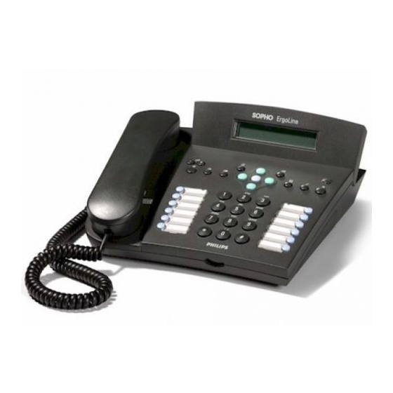
Customer Engineer Manual NTRODUCTION The SOPHO ErgoLine D330 and ErgoLine D340 are the first of a new range of digital terminals for use on the Philips iS3000 PABXs. The D330 and D340 are designed to replace the S370, S375, S375D, P370, P370D, P375 and P375D. -
Page 8: Keys
• Interchangeable line interfaces: • 4-wire S interface • 2-wire U interface • PC interface for use with TAPI compliant applications Variants • The ErgoLine D330 can hold up to 4 languages • A choice of two colours is available Page 1-2... -
Page 9: Ergoline D340
ErgoLine D330/D340 Customer Engineer Manual ErgoLine D340 User Features • Tiltable 4x40 alphanumeric display • Handset volume control • 12 key numeric keypad, all of which can also be used as speed-dial keys • Last number redial (10 numbers) • Last unanswered calls (15 numbers) •... -
Page 10: Interfaces
ErgoLine D330/D340 Customer Engineer Manual • Context sensitive Softkeys Interfaces • Static interface - an RJ11 socket on the terminal base which supplies input/output control. This can be used with a second bell, door opener or door lamp as output, or with a footpedal as input. -
Page 11: Quick Scan Card Of Ergoline Models
ErgoLine D330/D340 Customer Engineer Manual UICK ARD OF ODELS Description ErgoLine D330 ErgoLine D340 Screen size 2 x 24 4 x 40 Adjustable screen Soft keys none Programmable keys (attached label) 12 with LED 12 with LED Functions down-loadable (under keys) - Page 12 ErgoLine D330/D340 Customer Engineer Manual Note 1: The Infra-Red, Static, Audio Power and V.24 interfaces are not Supply available on the D330 Interchangeable Line Interface: - 2-wire U data V.24 - 4-wire S (B1) Line Interface Terminal Circuit Adapter Static...
-
Page 13: Physical Layout
ErgoLine D330/D340 Customer Engineer Manual HYSICAL AYOUT The physical parts of the ErgoLine D330 and D340 are illustrated in the following diagrams. 2x24 Display Loudspeaker Microphone Fixed Function Keys Volume Control Cursor Keys Programmable Keys Alpha-numeric Keys 1- 2 T E D330. - Page 14 ErgoLine D330/D340 Customer Engineer Manual 4x40 Display Soft Keys Loudspeaker Microphone Volume Control Fixed Function Keys Cursor Keys Programmable Keys Alpha-numeric Keys ASCII Keypad Infra-red Port 1-4. T D340 IGURE IEW OF RGOLINE V24 Data option PC Interface 2-wire/4-wire Line I/F...
- Page 15 ErgoLine D330/D340 Customer Engineer Manual 1-6. E IGURE XPLODED VIEW OF INE TERMINAL Page 1-9...
-
Page 16: Description Of Functions
ErgoLine D330/D340 Customer Engineer Manual ESCRIPTION OF UNCTIONS Numeric Keys The Numeric Keys are used when initiating a call, invoking an exchange facility, storing and retrieving numbers or when programming the ErgoLine. Programmable Keys The Programmable Keys can be used to store various PABX commands including speed-dial and group features. -
Page 17: Soft Keys (D340)
The ErgoLine D340 has four Soft Keys. These keys are used in conjunction with related functions displayed on the LCD. 2x24 Display (D330 only) The ErgoLine D330 has an LCD display with 2 lines of 24 alphanumeric characters. The display shows the following information: • Numbers/names dialled from the numeric keypad •... -
Page 18: Loudspeaker
The External Microphone is used during hands-free operation. 2-Wire/4-Wire Line Interface - Refer to page 2-41 for installation The ErgoLine D330 and ErgoLine D340 have modular line interfaces which allow the line interface to be changed from a 4-wire DTX-I S interface to a 2-wire DLX-U interface. -
Page 19: Dss Connector Cover (D340)
ErgoLine D330/D340 Customer Engineer Manual DSS Connector Cover (D340 only) - Refer to page 2-40 for more detail Additional Direct Station Select (DSS) modules can be connected to an ErgoLine D340. Each DSS module offers an additional 14 programmable keys. Up to three DSS modules can be fitted for a total of 42 additional keys. - Page 20 ErgoLine D330/D340 Customer Engineer Manual Page 1-14...
-
Page 21: Installation
The external power supply requires 220-240V AC, 50/60Hz mains power. The ErgoLine D330 and ErgoLine D340 are equipped with an EEPROM so programmed information is not lost if the power is removed. -
Page 22: Cabling
ErgoLine D330/D340 Customer Engineer Manual Cabling Power Cord (D340 only) The connection of the power cord to the transformer is fixed. The other end of the power cord terminates with a phono connector. Pin Outs Signal outside inside Handset Cord The handset is connected to the ErgoLine via a four wire coiled cord which termi- nates with a four way male modular plug at the terminal side. -
Page 23: Pnt1
A maximum two ErgoLine D330 terminals or two ErgoLine D340 terminals can be connected to the PNT1. The default TEI of the ErgoLine D330/D340 is 0. If two sets are connected to a PNT1 in a voice mode only situation, one of the sets requires the TEI to be changed to If the ErgoLine D340 is to be used in a speech and data mode, only one set can be connected to the PNT1. -
Page 24: Cable And Distances
Note 3: When cables are connected together additional attenuation, caused by the joints, will occur. When the ErgoLine D330 or D340 terminal is connected via a PNT1 to a DLC-U or a DLC-C/D the distance can be extended by 1500 m. In this case the attenuation of the cable used between the PNT1 and DLC may not exceed 15dB (at 100kHz, without noise insertion). - Page 25 ErgoLine D330/D340 Customer Engineer Manual TEI 0 ISPBX PNT1 1500 m DLC-C/D Direct connections using the DLC-U standard terminal line cord TEI 1 TEI 0 DLC-C/D 600 m 1500 m DLC-U point to point TEI 0 DLC-C/D 500 m 1500 m...
-
Page 26: Connecting The D330 Ergoline Terminal
ErgoLine D330/D340 Customer Engineer Manual Connecting the D330 ErgoLine Terminal The D330 ErgoLine terminal is connected as follows: 1. Connect the handset cord to the handset port on the underside of the ErgoLine terminal and put the handset on the cradle. -
Page 27: D330 Terminal Endpoint Identification (Tei)
In the specification of the terminal message protocol (TMP) a B channel is identified by a port number. The ErgoLine terminal uses fixed TEIs for B channel allocation. For ErgoLine D330 terminals the TEI can have two different values: 0 = B channel 0 1 = B channel 1 When 0 or 1 is selected only one B channel is used for voice. -
Page 28: Connecting The D340 Ergoline Terminal
ErgoLine D330/D340 Customer Engineer Manual 6. Press Shift, Hold. The following display will appear on the screen: [ Scroll, OK accept] ↓ Clear All Keys? 7. Scroll down until the Set TEI option is displayed and press OK key. The following display will appear on the screen:... -
Page 29: D340 Terminal Endpoint Identification (Tei)
ErgoLine D330/D340 Customer Engineer Manual When the ErgoLine terminal has been successfully connected to the following: • mains supply where necessary • PNT1 or wall socket The following display will appear on the screen: Non-Operational Directory Messages Features Keys The ErgoLine terminal is now ready to receive commands from the Switch. - Page 30 ErgoLine D330/D340 Customer Engineer Manual The following display will appear on the screen: à Set phone Options] Cancel Language Sounds SetMode 2. Press the SetMode (soft) key. The following display will appear on the screen: Set phone [Enter password] Password:_ Cancel 3.
-
Page 31: System Requirements
ErgoLine D330/D340 Customer Engineer Manual 7. Press the Change (soft) key to change the TEI number, then press the OK key to accept the new setting. The following display will appear on the screen: à Terminal endpoint i.d. set! Options] Cancel Downl. -
Page 32: Preparing Download Information
ErgoLine D330/D340 Customer Engineer Manual Preparing Download Information The following can be downloaded from the Switch to the ErgoLine: • V.24 port characteristics • Function key data • Facility codes and local functions V.24 Port Characteristics V.24 data (and function key data) can be downloaded from the Switch using... - Page 33 ErgoLine D330/D340 Customer Engineer Manual Table 2-2 shows whether facility codes need to be downloaded for a specific function. Downloading the facility codes is discussed in the following chapter. 2-2. F ABLE UNCTION ODES FOR UNCTION OWNLOADING FUNCTION FUNCTION TO BE...
-
Page 34: Function Key Layout
ErgoLine D330/D340 Customer Engineer Manual 2-2. F ABLE UNCTION ODES FOR UNCTION OWNLOADING FUNCTION FUNCTION TO BE NUMBER TO BE NUMBER TO BE STORED FACILITY CODE DOWNLOADED STORED ON FIRST ON SECOND LEVEL NUMBER LEVEL (optional) Activate auto answer None... - Page 35 ErgoLine D330/D340 Customer Engineer Manual Key 1 Key 7 Test 1/19 Test 1/23 SOPHO 0 SOPHO 6 Key 2 Key 8 Key 1 Key 2 Key 3 Test 1/13 Test 1/17 Test 1/32 Test 1/33 Test 1/34 SOPHO 1 SOPHO 27...
- Page 36 ErgoLine D330/D340 Customer Engineer Manual Key = Marking on the terminal (numbers in italics are keypad key numbers) Test = Indication on LCD during the keyboard test in the maintenance menu SOPHO = Function key numbering for downloading from SOPHO iS in function key menus.
-
Page 37: Facility Codes And Local Functions
Facility Codes and Local Functions To give the user full access to ISPBX and ErgoLine D330 and D340 facilities, it is necessary to download facility codes. These facility codes are used for translation when a function key has been programmed. Some codes need to be downloaded to allow... - Page 38 ErgoLine D330/D340 Customer Engineer Manual INFORMATION TO BE STORED FACILITY FUNCTION NUMBER DOWNLOADED NUMBER/FACILITY CODE RESULT ID 2 = 1hour Microphone blocked enable 0 = No, 1 = Yes One keystroke set-up 0 = No, 1 = Yes Add-on Activate 3-party call...
-
Page 39: System Preconditions
ErgoLine D330/D340 Customer Engineer Manual System Preconditions Facility class mark 12 must always be assigned to the ErgoLine terminal. Depending on the facilities required, other facility class marks must also be assigned to the ErgoLine terminal. For example, if the extension user wants to use the do-not-disturb facility, the facility class mark Dial Do-not-disturb must also be assigned. - Page 40 ErgoLine D330/D340 Customer Engineer Manual DISTURB FUNCTION CODE Extension is Do-not-disturb entitled: facility class mark 25. Facility codes for activate (facility number 28) and cancel (facility number 29) do-not-disturb have to be downloaded. IGHT BSENCE FUNCTION CODE Extension is either: •...
- Page 41 ErgoLine D330/D340 Customer Engineer Manual ESSAGE AITING FUNCTION CODE Messages are sent by the exchange. A key must be programmed on the set for Message Waiting LED. The LED can be programmed for a type 0, 1, or 2 message, meaning respectively : LED on, winking or flashing.
- Page 42 ErgoLine D330/D340 Customer Engineer Manual ENERAL ACILITY ANCEL FUNCTION CODE Facility code for 'general facility cancel' (facility number 53) has to be downloaded. BSENT RESENT TATUS FUNCTION CODE ISPBX must provide the absent/present status of executives and secretaries. Extension is a member of an executive/secretary combination and a display group.
- Page 43 ErgoLine D330/D340 Customer Engineer Manual 100) RIVATE FUNCTION CODE Facility code for call pick-up (facility number 49) has to be downloaded. Group arrangement has the pick-up property. 101) ERSONAL FUNCTION CODE Facility code for call pick-up (facility number 49) has to be downloaded.
- Page 44 ErgoLine D330/D340 Customer Engineer Manual 111) OOTPEDAL FUNCTION CODE Can only be switched on and off when the terminal is idle. Function can be activated via the toggle list or through a function code. 112) ECOND INGER FUNCTION CODE Can only be switched on and off when the terminal is idle.
- Page 45 ErgoLine D330/D340 Customer Engineer Manual EYSTROKE NO FUNCTION CODE Default setting is one keystroke set-up off (no). Local function code for one keystroke set-up yes/no (facility number 40) may be downloaded: the default setting is then overruled. Extension user can not change the setting any more if downloading was done with priority level 3.
-
Page 46: Downloading Examples
1. In this example we will assume that you wish to download two numbers for speed dialling to an ErgoLine D330/D340 user. Assume that you wish to store the number 0931945880635 under the first level of key 13 and the number 0931867990214 under the second level. - Page 47 1 (as the KEY-DATA or FACILITY-CODE parameter). Assume also that function key menu 2 is allocated to this ErgoLine D330/D340. Preparing the download information of the group ring facility is done by executing the following OM command: CHFKDA: 2,42,0,1,3;...
- Page 48 ErgoLine D330/D340 Customer Engineer Manual Using the download facility, the following example shows a group with a number of group facilities, line position, park position (group and private) and call pickup. DIGRPA:12096; prop group displ superv park ext-pr membe sw-all...
-
Page 49: Optional Interfaces
ErgoLine D330/D340 Customer Engineer Manual Optional Interfaces Audio Interface The ErgoLine D340 has an optional Audio interface which can be used to connect audio accessories such as a voice recorder. The Audio interface is connected via an RJ11 socket on the underside of the terminal. - Page 50 ErgoLine D330/D340 Customer Engineer Manual 2-5. S ABLE TATIC NTERFACE PECIFICATION Connector 6-pin RJ11 ≤ 0.9V Input Level - 0 ≥ 3.7V Input Level - 1 Input Impedance 10 kΩ (pull-up) 1.5 kΩ ± 10% Output Impedance 100 Ω Impedance +5V STAT 2-6.
-
Page 51: V.24 Interface Option
ErgoLine D330/D340 Customer Engineer Manual V.24 Interface Option The ErgoLine D340 terminal has an optional V.24 Data Interface. This interface conforms to the CCITT V.24/V28 recommendations for, respectively, the circuit functions and electrical characteristics. The V.24 Data Interface is an ISDN terminal adapter which enables communication with a similar device. - Page 52 ErgoLine D330/D340 Customer Engineer Manual 8. Replace the base and secure with screws. 9. Replace any auxiliary equipment and replace the handset plug. 10. Replace or fit the external power supply. 11. Replace the DSS/DSS cover. 12. Program the TEI to 0&1 via the Service Mode program.
- Page 53 ErgoLine D330/D340 Customer Engineer Manual TO/FROM CIRCUIT MNEMONIC DESCRIPTION Loopback / maintenance test Calling indicator from TSET Transmitter signal element timing (DTE source) Test indicator from Data Call Control To switch the telephone from Voice-mode to Data-mode press SHIFT and then ARROW RIGHT.
- Page 54 ErgoLine D330/D340 Customer Engineer Manual • Display Calling Number Data Transfer Parameters The baud rate can be set up to the rates specified in the following table. This transfer mode and rate adaptation are fixed for each baud rate. The rate must match the baud rate of the attached V.24 device.
- Page 55 ErgoLine D330/D340 Customer Engineer Manual Line Protocols 1. Flow Control The methods of flow control between the V.24 interface and the V.24 device are configurable. There are two hardware methods and one software method. These must be compatible with the method used by the attached V.24 device.
- Page 56 ErgoLine D330/D340 Customer Engineer Manual 2-11. V.25 ABLE ESSAGES HE FOLLOWING MESSAGES WILL BE RETURNED Call Failure Indication Incoming Call Valid Invalid Connection Established 2-12. C ABLE AILURE EASONS F A CALL FAILURE INDICATION IS RETURNED THE FOLLOWING REASONS MAY BE GIVEN...
- Page 57 ErgoLine D330/D340 Customer Engineer Manual Not used Not used Not used Not used Returns decimal value of register r Sr=xxx Program register r with xxx. Returns OK if x does not exceed the maximum value for r, otherwise ERROR is returned.
- Page 58 ErgoLine D330/D340 Customer Engineer Manual Not used Pause Duration for Dial Delay. Not supported. Default is ASCII 1 Not used Reaction Time to Received Carrier. Default is ASCII 6 Not used Time Delay from Loss of Carrier to Clearing of Connection. The synchronisation may be lost for up to 3 seconds.
-
Page 59: Pc Interface Option
ErgoLine D330/D340 Customer Engineer Manual PC Interface Option The PC Interface is standard on the ErgoLine D330 and D340. This PC interface is used for driving the terminal via a PC allowing TAPI-compliant applications to be used via this interface. -
Page 60: Installing The Dss Options
ErgoLine D330/D340 Customer Engineer Manual Installing the Direct Station Select (DSS) Options Up to three DSS options can be added to an ErgoLine D340 terminal. To install DSS options, proceed as follows: Note: The DSS module requires an external power supply to be fitted. -
Page 61: Installing Optional Line Interface
ErgoLine D330/D340 Customer Engineer Manual Installing Optional Line Interface The ErgoLine terminal can be fitted with either a 2-wire or a 4-wire line interface. To change the line interface, proceed as follows: WARNING: Do not open the ErgoLine terminal when line or external power is connected. -
Page 62: Ascii Keyboard
ErgoLine D330/D340 Customer Engineer Manual ASCII Keyboard The ErgoLine D340 terminal can have, as an option, a separate ASCII keyboard. It communicates with the ErgoLine terminal via an Infra-Red link. Note: If no ASCII keyboard is in use, it is recommended that the ASCII keyboard setting is switched off (this is the default condition). -
Page 63: International Character Selection
ErgoLine D330/D340 Customer Engineer Manual International Character Selection International characters can be selected on the ASCII keypad by pressing the grey key, located at the top right of the keypad, followed by one of the keys marked with a coloured circle. (For example, to select the character è, press the grey key then the E key. -
Page 64: Function Key Numbering
ErgoLine D330/D340 Customer Engineer Manual 2-13. S ASCII K IGURE ETTING THE HANNEL ON THE EYPAD Function Key Numbering As with the ErgoLine main terminal and the DSS options, the ASCII keypad has programmable function keys. These two keys are not downloadable but are programmable on both first and second levels. -
Page 65: Programming Telephone Parameters
Programming of the ErgoLine terminal is menu-driven. Navigation through the menus is done using the cursor keys on the ErgoLine D330 terminal, or via the four Softkeys on the ErgoLine D340 terminal. The Softkeys on the optional ASCII keypad behave in an identical manner to the Softkeys on the D340. -
Page 66: Ergoline D340 Programming Map
ErgoLine D330/D340 Customer Engineer Manual See User Guide for details. ErgoLine D340 Programming Map When programming the ErgoLine D340, use the following map to navigate through the various menu levels. Details of each programmed function is contained in the User Manual. -
Page 67: Terminal Locking And Unlocking Of The D330/D340
ErgoLine D330/D340 Customer Engineer Manual • Options marked ** are only available in Service mode. The Service mode password is 12687. See User Guide for details. Terminal Locking and Unlocking of the D330/D340 The user is able to lock the set using LOCK MODE. Consult the User Guide on how to do this. - Page 68 ErgoLine D330/D340 Customer Engineer Manual Page 3-4...
-
Page 69: Maintenance And Testing
Customer Engineer Manual AINTENANCE AND ESTING The following functional tests of the ErgoLine D330 & D340 terminals allow the Display, Keyboard, LEDs, Memory, EEPROM, Analogue Interfaces and Digital Interfaces to be tested. During the testing incoming calls can still be accepted. -
Page 70: Show Software Version
ErgoLine D330/D340 Customer Engineer Manual Test codes and descriptions are as follows: Show Software Version (Codes 1….. 6) Code 1 : displays the version number of the terminal software EPROM. Code 2 : displays the version number of the terminal key controller. -
Page 71: Memory Test
ErgoLine D330/D340 Customer Engineer Manual Memory Test (Codes 21… 27) Code 21 : verifies that RAM is operational Code 22 : verifies the checksum for each bank of ROM Code 23 : tests the EEPROM of the terminal for faulty memory cells... - Page 72 ErgoLine D330/D340 Customer Engineer Manual Note: Codes 57 and 58 are used in conjunction with the other codes. It is essential that forced transmit or receive is deactivated off before returning to user mode. See Note on page 4-4. Digital Interfaces (Codes 61… 70)
-
Page 73: Call Progress Codes
Customer Engineer Manual Call Progress Codes During a call the ISPBX sends call progress codes to the ErgoLine D330/D340, see Table 4-1. These codes are displayed on the left hand side and can be used as an indication when tracing a fault. - Page 74 ErgoLine D330/D340 Customer Engineer Manual Page 4-6...
-
Page 75: Introduction
NTRODUCTION The Sopho ErgoLine D310 and D320 complete the new range of digital terminals for use with the Philips iS3000 PABXs. The D310 and the D320 are designed to replace the P171, P271 and S271. The D320 and the D310 are both available with a 4-wire S0 interface and in a 2 wire Upn interface. -
Page 76: Ergoline D320
ErgoLine D310/320 Customer Engineer Manual ErgoLine D320 User Features • 1x 16 character display • date and time display • calling number display • call charge and duration display • scratch pad (to store the number of the connected party) •... -
Page 77: Quick Scan Card Of Ergoline Models D310 And D320
ErgoLine D310/320 Customer Engineer Manual Quick Scan Card of ErgoLine Models D310 and D320 Description ErgoLine D310 ErgoLine D320 Screen size not available 1 x 16 Adjustable screen Soft keys none none Programmable keys (attached label) 4 + 4 Functions down-loadable (under keys) Programmable memory (hidden label) Fixed function keys Cursor: horizontal, vertical and OK key... -
Page 78: Physical Layout
ErgoLine D310/320 Customer Engineer Manual HYSICAL AYOUT See related userguide. ESCRIPTION OF FUNCTIONS See related userguide. Page 5-4... -
Page 79: Installation
ErgoLine D310/320 Customer Engineer Manual Installation Cabling Handset Cord The handset is connected to the ErgoLine via a four wire coiled cord which termi- nates with a four way male modular plug at the terminal side. Pin Outs Signal Telephone Microphone + Microphone - Telephone... -
Page 80: Pnt1
The ErgoLine D310 and D320 can be connected to the switch via the DLX-U U interface. This is a two wire digital interface which uses ping-pong signalling. (Do not mistake this interface with the echo-cancelling proprietary Philips U-interface). This interface is capable of supporting the connection of one terminal only. -
Page 81: Cable And Distances
For the possible wiring configurations, see the chapter “Cables and Distances” on page 2-4 of the ErgoLine D330/D340 section of this manual. Note however that the ErgoLine D310 and D320 cannot be connected to a DLC-C or DLC-D via a PNT1. -
Page 82: Endgerät Auswal Ziffer (Eaz)
ErgoLine D310/320 Customer Engineer Manual • the D310 emits two beeps within 5 seconds. It is now operational the D320 displays the date and time ( or **-**-** if the date/time is not set in the switch) within 10 seconds. It is now operational. Endgerät Auswahl Ziffer (EAZ) Terminals must have an “equipment end dialling code”... -
Page 83: Adjusting The Eaz For D310
ErgoLine D310/320 Customer Engineer Manual Adjusting the EAZ for D310: The two settings EAZ can be programmed as follows: 1 place handset on hook 2 press PROGRAM key 3 press “9” 4 press PROGRAM key 5 press a character to change the setting for EAZ. 6 The character can be a digit, 0 to 9, or *. -
Page 84: Programming
ErgoLine D310/320 Customer Engineer Manual Programming For full programming instructions, see the userguide. It is also possible for the system engineer to protect the D320 against unauthorised programming. This is done as described below: Terminal (Un)locking of the D320 Terminal locking offers the possibility to block •... -
Page 85: Maintenance
ErgoLine D310/320 Customer Engineer Manual Maintenance The following functional tests of the ErgoLine D330 & D340 terminals allow the Display, Keyboard, LED’s, Memory and Interface to be tested. Self test of the ErgoLine D310 If the terminal is powered up with the handset on hook and the '*' and '#' keys pressed together a factory self test mode is entered. -
Page 86: Self Test Of The Ergoline D320
ErgoLine D310/320 Customer Engineer Manual Er goLi ne Hold Loudspeaker Program M N O PQRS W XYZ Memory Keys 5.1 D310 IGURE KEYS Self test of the ErgoLine D320 If the terminal is powered up with the handset on hook and the '*' and '#' keys pressed simultaneously a factory self test mode is entered. - Page 87 ErgoLine D310/320 Customer Engineer Manual 6 The IOM2 interface and CODEC are tested. If a fault occurs, the self test terminates and the message BAD IOM2/CODEC is displayed. 7 If all the previous tests have been successful then all dot segments of the dot matrix display are illuminated, all the LEDs are lit and a short beep is emitted.
- Page 88 ErgoLine D310/320 Customer Engineer Manual Page 5-14...