Table of Contents
Quick Links
See also:
Owner's Manual
SERVICE MANUAL
This service manual is for the EWD7003 Updated
Version that the serial number is later than D39310001.
The model differs from the previous EWD7003, and that a
star mark (
) is printed on the rating label is its
applicable model. For the rating label on the rear panel,
refer to below.
star mark
rating label
serial number
DVD PLAYER
EWD7003
Table of Contents

Related Manuals for Emerson EWD7003


Summary of Contents for Emerson EWD7003
-
Page 1: Dvd Player
SERVICE MANUAL This service manual is for the EWD7003 Updated Version that the serial number is later than D39310001. The model differs from the previous EWD7003, and that a star mark ( ) is printed on the rating label is its applicable model. -
Page 2: Table Of Contents
IMPORTANT SAFETY NOTICE Proper service and repair is important to the safe, reliable operation of all Funai Equipment. The service procedures recommended by Funai and described in this service manual are effective methods of performing service operations. Some of these service special tools should be used when and as recommended. -
Page 3: Specifications
SPECIFICATIONS ITEM CONDITIONS UNIT NOMINAL LIMIT 1. Video Output 75 ohm load ± 0.1 2. Coaxial Digital Out 75 ohm load mVpp ± 100 3. Audio (PCM) 3-1. Output Level 1kHz 0dB Vrms 3-2. S/N 3-3. Freq. Response fs=48kHz 20~22kHz ±... -
Page 4: Laser Beam Safety Precautions
LASER BEAM SAFETY PRECAUTIONS This DVD player uses a pickup that emits a laser beam. Do not look directly at the laser beam coming from the pickup or allow it to strike against your skin. The laser beam is emitted from the location shown in the figure. When checking the laser diode, be sure to keep your eyes at least 30cm away from the pickup lens when the diode is turned on. -
Page 5: Important Safety Precautions
IMPORTANT SAFETY PRECAUTIONS Product Safety Notice I. Also check areas surrounding repaired locations. J. Be careful that foreign objects (screws, solder Some electrical and mechanical parts have special droplets, etc.) do not remain inside the set. safety-related characteristics which are often not evi- K. -
Page 6: Safety Check After Servicing
Safety Check after Servicing Examine the area surrounding the repaired location for damage or deterioration. Observe that screws, parts, Chassis or Secondary Conductor and wires have been returned to their original posi- tions. Afterwards, do the following tests and confirm the specified values to verify compliance with safety Primary Circuit Terminals standards. -
Page 7: Standard Notes For Servicing
STANDARD NOTES FOR SERVICING Circuit Board Indications How to Remove / Install Flat Pack-IC 1. The output pin of the 3 pin Regulator ICs is indi- 1. Removal cated as shown. With Hot-Air Flat Pack-IC Desoldering Machine:. (1) Prepare the hot-air flat pack-IC desoldering Top View Bottom View machine, then apply hot air to the Flat Pack-IC... - Page 8 With Soldering Iron: (4) Bottom of the flat pack-IC is fixed with glue to the CBA; when removing entire flat pack-IC, first apply (1) Using desoldering braid, remove the solder from all soldering iron to center of the flat pack-IC and heat pins of the flat pack-IC.
- Page 9 2. Installation Instructions for Handling Semi-conductors (1) Using desoldering braid, remove the solder from the foil of each pin of the flat pack-IC on the CBA Electrostatic breakdown of the semi-conductors may so you can install a replacement flat pack-IC more occur due to a potential difference caused by electro- easily.
-
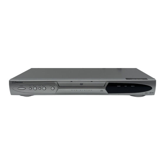
Page 10: Operating Controls And Functions
OPERATING CONTROLS AND FUNCTIONS FRONT PANEL [Fig. 1] REAR VIEW AUDIO OUT COMPONENT VIDEO OUT DIGITAL AUDIO OUT PCM/ BITSTREAM COAXIAL VIDEO S-VIDEO OUT [Fig. 2] 1. POWER 10. DISC IN Indicator to switch the player to ON or OFF light appears when a disc is in the DVD player. -
Page 11: Cabinet Disassembly Instructions
CABINET DISASSEMBLY INSTRUCTIONS 1. Disassembly Flowchart (1): Identification (location) No. of parts in the figures (2): Name of the part This flowchart indicates the disassembly steps to gain (3): Figure Number for reference access to item(s) to be serviced. When reassembling, (4): Identification of parts to be removed, unhooked, follow the steps in reverse order. - Page 12 DVD Mecha [1] Top Cover (S-1) (S-1) (S-1) Short the three short lands by soldering Fig. D1 Tray Panel Connector (L-2) View for A (L-1) (L-1) (L-4) Slide (L-4) Short the three short lands by soldering FPC Cable [2] Front Assembly (L-3) Pickup Unit Fig.
- Page 13 (S-6) [4] AV CBA (S-7) (S-4) (S-4) [6] Function [7] Main CBA (S-5) Holder CN401 CN601 (S-5) CN2001 [5] DVD Main CBA Unit (S-3) [8] Rear Panel Fig. D6 Fig. D5 HOW TO MANUAL EJECT 1. Remove the Top Case. 2.
-
Page 14: Block Diagrams
BLOCK DIAGRAMS System Control/Servo Block Diagram SLED SERVO SIGNAL SPINDLE SERVO SIGNAL FOCUS SERVO SIGNAL TRACKING SERVO SIGNAL IC101 (MICRO CONTROLLER) PCM-SCLK 163 PCM-SCLK A-MUTE A-MUTE ADAC-MD VIDEO/ AUDIO ADAC-MD ADAC-MC BLOCK DIAGRAM 56 ADAC-MC ADAC-ML 58 ADAC-ML IC301 VREF (SERVO DRIVE) FS(+) FOCUS... -
Page 15: Digital Signal Process Block Diagram
Digital Signal Process Block Diagram DATA(AUDIO) SIGNAL DATA(VIDEO/AUDIO) SIGNAL VIDEO SIGNAL FOCUS SERVO SIGNAL TRACKING SERVO SIGNAL IC102 (SDRAM) IC101 (MICRO CONTROLLER) SDRAM ADDRESS(0-11) SDRAM ADDRESS(0-11) DATA SDRAM EXTERNAL MEMORY DECODER INST. DECODER STREAM SDRAM DATA(0-15) SDRAM DATA(0-15) DATA PROCESSOR INST. - Page 16 Video / Audio Block Diagram DATA(AUDIO) SIGNAL AUDIO SIGNAL VIDEO SIGNAL IC1402 (VIDEO DRIVER) DRIVER JK1401 S-VIDEO OUT DRIVER CN601 CN1601 DRIVER VIDEO-Y VIDEO-Y TO DIGITAL VIDEO-C VIDEO-C JK1404 SIGNAL PROCESS VIDEO-Cb BLOCK DIAGRAM VIDEO-Cb DRIVER COMPOSITE VIDEO-Cr VIDEO-Cr VIDEO OUT DRIVER VIDEO-Y VIDEO-Cb...
-
Page 17: Power Supply Block Diagram
Power Supply Block Diagram CAUTION ! CAUTION Fixed voltage ( or Auto voltage selectable ) power supply circuit is used in this unit. FOR CONTINUED PROTECTION AGAINST FIRE HAZARD, NOTE : If Main Fuse (F1001) is blown, check to see that all components in the power supply REPLACE ONLY WITH THE SAME TYPE FUSE. -
Page 18: Schematic Diagrams / Cba's And Test Points
SCHEMATIC DIAGRAMS / CBA’S AND TEST POINTS Standard Notes WARNING Many electrical and mechanical parts in this chassis have special characteristics. These characteristics often pass unnoticed and the protection afforded by them cannot necessarily be obtained by using replace- ment components rated for higher voltage, wattage, etc. - Page 19 LIST OF CAUTION, NOTES, AND SYMBOLS USED IN THE SCHEMATIC DIAGRAMS ON THE FOLLOWING PAGES: 1. CAUTION: FOR CONTINUED PROTECTION AGAINST FIRE HAZARD, REPLACE ONLY WITH THE SAME TYPE FUSE. ATTENTION: POUR UNE PROTECTION CONTINUE LES RISQES D'INCELE N'UTILISER QUE DES FUSIBLE DE MÊME TYPE. RISK OF FIRE-REPLACE FUSE AS MARKED.
- Page 20 DVD Main 1/3 Schematic Diagram SPINDLE SERVO SIGNAL DATA(VIDEO+AUDIO) FOCUS SERVO SIGNAL TRACKING SERVO SIGNAL SLED SERVO SIGNAL DVD MAIN 1/3 Ref No. Position IC201 IC202 IC301 IC461 TRANSISTORS Q251 Q252 Q253 Q254 CONNECTORS CN201 CN301 CN401 1-8-3 1-8-4 E58T0SCD1...
- Page 21 DVD Main 2/3 Schematic Diagram DATA(VIDEO+AUDIO) FOCUS SERVO SIGNAL SPINDLE SERVO SIGNAL DATA (AUDIO) VIDEO SIGNAL TRACKING SERVO SIGNAL SLED SERVO SIGNAL DVD MAIN 2/3 Ref No. Position IC101 1-8-5 1-8-6 E58T0SCD2...
- Page 22 IC101 VOLTAGE CHART PIN.NO PLAY STOP PIN.NO PLAY STOP PIN.NO PLAY STOP PIN.NO PLAY STOP PIN.NO PLAY STOP PIN.NO PLAY STOP PIN.NO PLAY STOP PIN.NO PLAY STOP ----- ----- ----- ----- ----- ----- ----- ----- ----- ----- ----- ----- ----- ----- ----- -----...
- Page 23 DVD Main 3/3 Schematic Diagram VIDEO SIGNAL DATA (AUDIO) AUDIO SIGNAL DVD MAIN 3/3 Ref No. Position IC102 IC103 IC601 CONNECTOR CN601 1-8-9 1-8-10 E58T0SCD3...
- Page 24 AV 1/3 Schematic Diagram CAUTION CAUTION ! NOTE : FOR CONTINUED PROTECTION AGAINST FIRE HAZARD, Fixed voltage ( or Auto voltage selectable ) power supply circuit is used in this unit. The voltage for parts in hot circuit is measured REPLACE ONLY WITH THE SAME TYPE FUSE.
- Page 25 AV 2/3 Schematic Diagram VIDEO SIGNAL DATA (AUDIO) AUDIO SIGNAL AV 2/3 Ref No. Position IC1201 IC1402 TRANSISTORS Q1201 Q1202 Q1203 Q1204 Q1351 Q1352 CONNECTOR CN1601 1-8-13 1-8-14 E58T0SCAV2...
- Page 26 AV 3/3 & Function Schematic Diagram AV 3/3 Ref No. Position IC2001 TRANSISTORS Q2001 Q2003 CONNECTORS CN2001 1-8-15 1-8-16 E58T0SCAV3...
- Page 27 AV CBA Top View CAUTION ! NOTE : Fixed voltage ( or Auto voltage selectable ) power supply circuit is used in this unit. The voltage for parts in hot circuit is measured If Main Fuse (F1001) is blown, check to see that all components in the power supply using hot GND as a common terminal.
- Page 28 AV CBA Bottom View CAUTION ! NOTE : Fixed voltage ( or Auto voltage selectable ) power supply circuit is used in this unit. The voltage for parts in hot circuit is measured If Main Fuse (F1001) is blown, check to see that all components in the power supply using hot GND as a common terminal.
- Page 29 FUNCTION CBA Top View FUNCTION CBA Bottom View 1-8-21 1-8-22 BE5800F01011B...
-
Page 30: Waveforms
WAVEFORMS Pin 5 of CN1601 Pin 13 of CN1601 NOTE: Input CD: 1kHz PLAY (WF4~WF6) DVD: POWER ON (STOP) MODE (WF1~WF3) VIDEO-Y 0.2V 20µsec AUDIO-R 0.5msec Pin 7 of CN1601 Pin 16 of CN1601 VIDEO-C 0.2V 20µsec SPDIF 0.1µsec Pin 21 of IC1402 VIDEO-CVBS 0.5V 20µsec... -
Page 31: Wiring Diagram
WIRING DIAGRAM VIDEO-Y VIDEO-Cb VIDEO-Cr VIDEO AUDIO-L AUDIO-R DIGITAL S-VIDEO AC CORD AUDIO OUT CN2001 CN2002 KEY-2 FUNCTION CBA AV CBA KEY-3 (BE5800F01011A) (BE5800F01011B) KEY-1 KEY-4 CN2002 is soldered directly to the PCB. CN1001 CN1601 (CN1001 is soldered directly to the PCB.) (CN1601 is soldered directly to the PCB.) CN401 CN601... -
Page 32: Firmware Renewal Mode
FIRMWARE RENEWAL MODE 1. Turn the power on and remove the disc on the tray. 2. To put the DVD player into version up mode, press F/W Version Up Mode [9], [8], [7], [6], and [SEARCH MODE] buttons on the remote control unit in that order. The tray will VERSION : ******** Completed... -
Page 33: System Control Timing Charts
SYSTEM CONTROL TIMING CHARTS Tray Close ~ Play / Play ~ Tray Open Disc Tray Tray Disc Stop Open Close Rotation Play 3.3V Tray OUT (TL220) 3.3V Tray IN (TL221) 1.65V Sled Drive (TP303) 1.65V Disc Drive (TP301) 1.65V Focus Drive (TP304) 1.65V Tracking Drive... -
Page 34: Ic Pin Function Descriptions
IC PIN FUNCTION DESCRIPTIONS IC2001 [ PT6313-S-TP ] Signal In/Out Name Function Name FP-CLK Clock Input FP-STB Serial Interface Strobe Key Data 1 Input Key Data 2 Input Power Supply KEY-1 Key Source-1 KEY-2 Key Source-2 KEY-3 Key Source-3 KEY-4 Key Source-4 Not Used Not Used... -
Page 35: Lead Identifications
LEAD IDENTIFICATIONS 2SK3374 2SC2785 (H) 2SA1015-Y (TPE2) KTC3199 (GR) KTA1266 (Y) KTA1267 (Y) KTC3198 (Y) 2SC2120-Y(TPE2) KTC3203(Y) KRC101M BA1L3M-T S D G E C B E C B NJM4558D KIA431-AT MM1622XJBE PT6313-S-TP KIA4558P FAN431AZXA PQ070XF01SZ K A R LTV-817(B,C)-F Note: 1: Vin A: Anode 2: Vo... -
Page 36: Exploded Views
EXPLODED VIEWS Cabinet 2L011 2L011 2L011 See Electrical Parts List for parts with this mark. 2L011 2L105 Some Ref. Numbers are not in sequence. DVD Main 2L011 CBA Unit JK1401 2L031 JK1404 JK1202 FUNCTION CBA F1001 2L021 2L031 2L021 AV CBA 2L101 AC1001 2L021... - Page 37 Packing Unit 1-15-2 E58T0EX...
-
Page 38: Mechanical Parts List
MECHANICAL PARTS LIST PRODUCT SAFETY NOTE: Products marked with a # have special characteristics important to safety. Before replacing any of these components, read care- fully the product safety notice in this service manual. Don't degrade the safety of the product through improper servicing. -
Page 39: Electrical Parts List
ELECTRICAL PARTS LIST PRODUCT SAFETY NOTE: Products marked with a Ref. No. Description Part No. # have special characteristics important to safety. C1036 CHIP CERAMIC CAP. B K 0.01µF/50V CHD1JK30B103 Before replacing any of these components, read care- C1037 CHIP CERAMIC CAP. F Z 0.1µF/50V CHD1JZ30F104 fully the product safety notice in this service manual. - Page 40 Ref. No. Description Part No. Ref. No. Description Part No. D1005 RECTIFIER DIODE 1N4005 NDQZ001N4005 L1351 INDUCTOR 0.47µH-K-26T LLAXKATTUR47 D1006 SCHOTTKY BARRIER DIODE SB140 or NDQZ000SB140 L1401 CHIP INDUCTOR BK1608HM121-T LLBC003TU051 SCHOTTKY BARRIER DIODE ERA81-004 QDPZERA81004 L1421 CHIP INDUCTOR BK1608HM121-T LLBC003TU051 D1008 SCHOTTKY BARRIER DIODE SB140 or...
- Page 41 Ref. No. Description Part No. Ref. No. Description Part No. CHIP RES.(1608) 1/16W F 2.4k Ω or CHIP RES.(1608) 1/10W J 470 Ω R1023 RRXGFR5Z0242 R1397 RRXAJR5Z0471 CHIP RES.(1608) 1/10W F 2.4k Ω CHIP RES.(1608) 1/10W J 75 Ω RRXAFR5Z2401 R1402 RRXAJR5Z0750 CHIP RES.(1608) 1/10W J 10k Ω...
- Page 42 Ref. No. Description Part No. CHIP RES.(1608) 1/10W 0 Ω R2108 RRXAZR5Z0000 SWITCHES SW2001 TACT SWITCH KSM0614B or SST0101HH013 TACT SWITCH SKQSAF001A SST0101AL041 SW2002 TACT SWITCH KSM0614B or SST0101HH013 TACT SWITCH SKQSAF001A SST0101AL041 SW2003 TACT SWITCH KSM0614B or SST0101HH013 TACT SWITCH SKQSAF001A SST0101AL041 SW2005 TACT SWITCH KSM0614B or...
- Page 43 Printed in Japan 2003-10-24 HO...