
Related Manuals for Saftronics FP5 Series


Summary of Contents for Saftronics FP5 Series
- Page 1 - Control Techniques,emerson,saftronics -ac drive-servo motor FP5/GP5 Series User’s Manual Variable Torque Inverter (with software version 5110/5120 and newer)
- Page 2 Every precaution has been taken in the prepara- tion of this manual. Nevertheless, Saftronics assumes no responsibility for errors or omissions. Neither is any liability assumed for damages result- ing from the use of the information contained in this publication.
-
Page 3: Table Of Contents
- Control Techniques,emerson,saftronics -ac drive-servo motor Contents CONTENTS Section Description Page RECEIVING & INSTALLATION ........6 NTRODUCTION . - Page 4 - Control Techniques,emerson,saftronics -ac drive-servo motor Contents Current limit (Stall prevention)....52 DC injection braking ......54 Energy savings control .
-
Page 5: Description
- Control Techniques,emerson,saftronics -ac drive-servo motor Chapter 1 - Receiving & Installation - CHAPTER 1 - RECEIVING & INSTALLATION Section Description Page RECEIVING & INSTALLATION ........6 NTRODUCTION . -
Page 6: Introduction
- Control Techniques,emerson,saftronics -ac drive-servo motor Chapter 1 - Receiving & Installation Introduction 1.1 INTRODUCTION high quality, The FP5/GP5 is a series of full featured inverters. With a power range of 5 to 500 HP, it provides all the functionality of prior series, in a compact, low cost package. -
Page 7: Specifications
- Control Techniques,emerson,saftronics -ac drive-servo motor Chapter 1 - Receiving & Installation Specifications 1.2 SPECIFICATIONS FP5/GP5 Inverter Model CIMR-P5U 20P4 20P7 21P5 22P2 23P7 25P5 27P5 2011 2015 Motor Output (HP) * Capacity (kVA) Rated Output 17.5 Current (A)-VT** Rated Output 17.5... - Page 8 - Control Techniques,emerson,saftronics -ac drive-servo motor Chapter 1 - Receiving & Installation Specifications Control Method Sine wave PWM with full-range, automatic torque boost Frequency Control 0.1 to 400 Hz Range Frequency Accuracy Digital command: 0.01%, Analog command: 0.1% Frequency Setting Reso- Digital Operator Reference: 0.1Hz,...
- Page 9 - Control Techniques,emerson,saftronics -ac drive-servo motor Chapter 1 - Receiving & Installation Specifications FP5/GP5 Inverter Model CIMR-P5U 2018 2022 2030 2037 2045 2055 2075 Motor Output (HP) * 100 125 Capacity (kVA) — Rated Output 104 130 160 192 248 312...
- Page 10 - Control Techniques,emerson,saftronics -ac drive-servo motor Chapter 1 - Receiving & Installation Specifications Control Method Sine wave PWM with full-range, automatic torque boost Frequency Control Range 0.1 to 400 Hz Frequency Accuracy Digital command: 0.01%, Analog command: 0.1% Frequency Setting Digital Operator Reference: 0.1Hz,...
-
Page 11: Preliminary Inspection
- Control Techniques,emerson,saftronics -ac drive-servo motor Chapter 1 - Receiving & Installation Preliminary Inspection 1.3 PRELIMINARY INSPECTION Receiving After unpacking the FP5/GP5: · Verify that the part numbers on the drive nameplate match the num- bers on your purchase order or packing slip. -
Page 12: Identifying The Parts
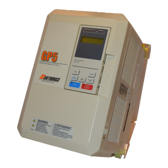
- Control Techniques,emerson,saftronics -ac drive-servo motor Chapter 1 - Receiving & Installation Preliminary Inspection Identifying the Parts Protective Cover (top/bottom) 4 Mounting Holes Digital Operator JVOP-130P Heatsink Front Cover Nameplate Ventilation Slots Figure 3 Parts Identification - Model P5U43P7... -
Page 13: Mounting
- Control Techniques,emerson,saftronics -ac drive-servo motor Chapter 1 - Receiving & Installation Mounting 1.4 MOUNTING CAUTION PRECAUTIONS 1) When preparing to mount the FP5/GP5, lift it by its base. Never lift it by the front cover. 2) Mount the inverter onto nonflammable material. -
Page 14: Removing And Replacing The Digital Operator
- Control Techniques,emerson,saftronics -ac drive-servo motor Chapter 1 - Receiving & Installation Mounting Removing and Replacing the Digital Operator To remove the digital operator from the front cover, push the operator lever in the direction shown by arrow 1 and lift the digital operator in the direction shown by arrow 2 (see Figure 4). -
Page 15: Dimensions/Heat Loss
- Control Techniques,emerson,saftronics -ac drive-servo motor Chapter 1 - Receiving & Installation Mounting Dimensions/Heat Loss Open Chassis Type (IP00) Open Chassis Dimensions in inches (mm) Heat Loss (W) Model Mass Voltage CIMR Heat Inside lbs (kg) Total sink unit... - Page 16 - Control Techniques,emerson,saftronics -ac drive-servo motor Chapter 1 - Receiving & Installation Mounting Enclosed Type (NEMA 1, IP20) Model NEMA 1 Dimensions in inches (mm) Mass Voltage (CIMR- lbs (kg) P5U) 20P4 20P7 5.51 (140) 11.02 (280) 6.30 (160) 4.96 (126)
-
Page 17: Clearances
- Control Techniques,emerson,saftronics -ac drive-servo motor Chapter 1 - Receiving & Installation Mounting Front View Side View Figure 7 FP5/GP5 Dimension Diagram Clearances When mounting the FP5/GP5, allow sufficient clearances for effec- tive cooling as shown below: 1.97in (50mm) 4.72in (120mm) -
Page 18: Wiring
- Control Techniques,emerson,saftronics -ac drive-servo motor Chapter 1 - Receiving & Installation Wiring 1.5 WIRING CAUTION PRECAUTIONS 1) Do not connect or disconnect wiring, or perform signal checks while the power supply is turned ON. 2) Connect the power supply wiring to terminals L1, L2 and L3 on the main circuit input section. -
Page 19: Fp5/Gp5 Connection Diagram
- Control Techniques,emerson,saftronics -ac drive-servo motor Chapter 1 - Receiving & Installation Wiring FP5/GP5 Standard Connection Diagram 230V: Models 20P4 through 27P5 460V: Models 40P4 through 4015 B1 B2 DC Link Reactor (option) ⊕1 ⊕2 Ground Gate Drive 230V units: 100Ω or less 460V units: 10Ω... - Page 20 - Control Techniques,emerson,saftronics -ac drive-servo motor Chapter 1 - Receiving & Installation Wiring FP5/GP5 Standard Connection Diagram 230V: Models 2018 through 2075 460V: Models 4018 through 4160 Ground Gate Drive 230V units: 100Ω or less 460V units: 10Ω or less...
-
Page 21: Main Circuit Wiring
- Control Techniques,emerson,saftronics -ac drive-servo motor Chapter 1 - Receiving & Installation Wiring Main Circuit Wiring Input Wiring · Molded-Case Circuit Breaker (MCCB) Be sure to connect MCCBs or fuses between the AC main circuit power supply and FP5/GP5 input terminals L1, L2 and L3, to protect the power supply wiring. - Page 22 (100m) Carrier Frequency * 15kHz or less 10kHz or less 5kHz or less (Set value of parameter n054) * Increasing the carrier frequency above the factory default value requires current derating. Contact your Saftronics representative for details. FP5/GP5 User’s Manual...
- Page 23 - Control Techniques,emerson,saftronics -ac drive-servo motor Chapter 1 - Receiving & Installation Wiring Grounding · Ground Resistance 230V class: 100Ω or less, 460V class: 10Ω or less. · Never ground the FP5/GP5 in common with welding machines, motors, or other high-current electrical equipment. Run all ground wir- ing in a separate conduit.
-
Page 24: Terminal Functions
- Control Techniques,emerson,saftronics -ac drive-servo motor Chapter 1 - Receiving & Installation Wiring Terminal Functions 230V Class Terminal Functions Model CIMR-P5U 20P4 to 27P5 2011 to 2015 2018 to 2075 Nominal Motor Output 0.5 to 10HP 20 to 25HP... -
Page 25: Wire And Terminal Screw Sizes
- Control Techniques,emerson,saftronics -ac drive-servo motor Chapter 1 - Receiving & Installation Wiring Wire and Terminal Screw Sizes 230V Class Wire Size Wire Size * Model Terminal Max. Torque Circuit Terminal Symbol Wire Type CIMR- Screw lb-in (N·m) L1, L2, L3, , ⊕1, ⊕2, B1, B2, T1, T2, T3... - Page 26 - Control Techniques,emerson,saftronics -ac drive-servo motor Chapter 1 - Receiving & Installation Wiring 460V Class Wire Size Wire Size * Model Terminal Max. Torque Circuit Terminal Symbol Wire Type CIMR- Screw lb-in (N·m) L1, L2, L3, , ⊕1, ⊕2, B1, B2, T1, T2, T3...
- Page 27 M12 x 2 325 - 12 349.6 (39.5) 650MCM 325 - 16 867.4 (98.0) Note: The use of a JST closed-loop connector (lug) is recommended to maintain proper clearances. Please contact your Saftronics representative for more information. FP5/GP5 User’s Manual...
-
Page 28: Control Circuit Wiring
- Control Techniques,emerson,saftronics -ac drive-servo motor Chapter 1 - Receiving & Installation Wiring Control Circuit Wiring The following table outlines the functions of the control circuit terminals. Control Circuit Terminals Classifi- Terminal Function Description Signal Level cation Forward run/stop... -
Page 29: Operation
- Control Techniques,emerson,saftronics -ac drive-servo motor Chapter 2 - Operation - CHAPTER 2 - OPERATION Section Description Page OPERATION Precautions........30 . -
Page 30: Precautions
- Control Techniques,emerson,saftronics -ac drive-servo motor Chapter 2 - Operation Precautions WARNING PRECAUTIONS 1) Only turn ON the input power supply after replacing the front cover. Do not remove the cover while the inverter is powered up. 2) When the retry function (n060) is selected, do not approach the inverter or the load, since it may restart suddenly after being stopped. -
Page 31: Trial Operation
- Control Techniques,emerson,saftronics -ac drive-servo motor Chapter 2 - Operation Trial Operation 2.1 TRIAL OPERATION To ensure safety, prior to initial operation, disconnect the machine cou- pling so that the motor is isolated from the machine. If initial operation must be performed while the motor is still coupled to the machine, use great care to avoid potentially hazardous conditions. -
Page 32: Operation Checkpoints
- Control Techniques,emerson,saftronics -ac drive-servo motor Chapter 2 - Operation Trial Operation Operation Checkpoints: · Motor rotates smoothly. · Motor rotates in the correct direction. · Motor has no abnormal vibration and is not noisy. · Acceleration and deceleration are smooth. -
Page 33: Trial Operation
- Control Techniques,emerson,saftronics -ac drive-servo motor Chapter 2 - Operation Trial Operation Typical Operation Example by Digital Operator (JVOP-130P) Description Key Sequence Digital Operator Display (1) Power ON · Displays frequency reference value. REMOTE LED (SEQ, REF) ON Frequency Ref 0.0 Hz... - Page 34 - Control Techniques,emerson,saftronics -ac drive-servo motor Chapter 2 - Operation Trial Operation Operation by Control Circuit Terminal Signal The diagram below shows a typical operation pattern using the control circuit terminal signals. Forward 60Hz Power ON Operation Stop Frequency Setting...
-
Page 35: Digital Operator Display
- Control Techniques,emerson,saftronics -ac drive-servo motor Chapter 2 - Operation Digital Operator Display 2.2 DIGITAL OPERATOR DISPLAY All functions of the FP5/GP5 are accessed using the JVOP-130P Digi- tal Operator. Below are descriptions of the display and keypad sections. -
Page 36: Led Description
- Control Techniques,emerson,saftronics -ac drive-servo motor Chapter 2 - Operation LED Description 2.3 LED DESCRIPTION Simple operation of the FP5/GP5 is possible, by using the quick-start displays. Quick-Start Displays (Example of CIMR-P5U23P7) Description Key Sequence Digital Operator Display Remarks... -
Page 37: Operation Mode Selection
- Control Techniques,emerson,saftronics -ac drive-servo motor Chapter 2 - Operation Operation Mode Selection 2.4 OPERATION MODE SELECTION (n002, Oper Mode Select) The FP5/GP5 has two operation modes: LOCAL and REMOTE (see table below for description). These two modes can be selected by the digital operator “LOCAL/REMOTE”... - Page 38 - Control Techniques,emerson,saftronics -ac drive-servo motor This page intentionally left blank. FP5/GP5 User’s Manual...
-
Page 39: Programming Features
- Control Techniques,emerson,saftronics -ac drive-servo motor Chapter 3 - Programming Features - CHAPTER 3 - PROGRAMMING FEATURES Section Description Page PROGRAMMING FEATURES FP5/GP5 P (n001~n116) ... ARAMETERS & I . - Page 40 - Control Techniques,emerson,saftronics -ac drive-servo motor Chapter 3 - Programming Features Stopping method ....... 70 Torque adjustment.
-
Page 41: Fp5/Gp5 Parameters (N001~N116)
- Control Techniques,emerson,saftronics -ac drive-servo motor Chapter 3 - Programming Features FP5/GP5 Parameters 3.1 FP5/GP5 Parameters (n001~n116) Function Name Description Factory User Ref. (LCD Operator Display) Default Setting Page n001 Parameter selection/ 0: n001 read and set, n002~n116 read only... - Page 42 - Control Techniques,emerson,saftronics -ac drive-servo motor Chapter 3 - Programming Features FP5/GP5 Parameters Function Name Description Factory User Ref. (LCD Operator Display) Default Setting Page n014 Mid. output frequency Unit: 0.1Hz (Mid Frequency) Setting range: 0.1~399.9Hz n015 Mid. frequency voltage Unit: 0.1V...
- Page 43 - Control Techniques,emerson,saftronics -ac drive-servo motor Chapter 3 - Programming Features FP5/GP5 Parameters Function Name Description Factory User Ref. (LCD Operator Display) Default Setting Page LED Setting LCD Setting Description n034 Motor thermal protection (Motor OL Sel) Motor/ Disabled...
- Page 44 - Control Techniques,emerson,saftronics -ac drive-servo motor Chapter 3 - Programming Features FP5/GP5 Parameters Function Name Description Factory User Ref. (LCD Operator Display) Default Setting Page n037 Multi-function input 2 Set items are same as n036. (Terminal S3 Sel) (When n036=”FWD/REV Cmd (3W), “In Use By Fault Other”...
- Page 45 - Control Techniques,emerson,saftronics -ac drive-servo motor Chapter 3 - Programming Features FP5/GP5 Parameters Function Name Description Factory User Ref. (LCD Operator Display) Default Setting Page n047 Frequency reference level Unit: 1% at loss of Fref Setting range: 0~100% of setting Fref...
- Page 46 - Control Techniques,emerson,saftronics -ac drive-servo motor Chapter 3 - Programming Features FP5/GP5 Parameters Function Name Description Factory User Ref. (LCD Operator Display) Default Setting Page n065 Elapsed timer selection Time Setting LCD Setting Description Running (Elapsed Timer) Time Power is ON Accumulate time during power on...
- Page 47 - Control Techniques,emerson,saftronics -ac drive-servo motor Chapter 3 - Programming Features FP5/GP5 Parameters Function Name Description Factory User Ref. (LCD Operator Display) Default Setting Page n078 Over/Undertorque Unit: 1% 160% detection level OL3 Setting range: 30~200% (Torq Det Level)
- Page 48 - Control Techniques,emerson,saftronics -ac drive-servo motor Chapter 3 - Programming Features Parameter Set-up & Initialization Function Name Description Factory User Ref. (LCD Operator Display) Default Setting Page n096 Energy saving selection Disabled 55,96 Setting LCD Setting Description (Energy Save Sel) Disabled Energy saving is disabled.
-
Page 49: Parameter Set-Up & Initialization
- Control Techniques,emerson,saftronics -ac drive-servo motor Chapter 3 - Programming Features FP5/GP5 Operation Function Name Description Factory User Ref. (LCD Operator Display) Default Setting Page n112 Low frequency OL start Unit: 0.1Hz 6.0Hz point Setting range: 0.0 ~ 10.0Hz... -
Page 50: Fp5/Gp5 Operation
- Control Techniques,emerson,saftronics -ac drive-servo motor Chapter 3 - Programming Features FP5/GP5 Operation 3.3 FP5/GP5 OPERATION Accel/Decel Time Adjustment Decel Time 1 (n019) Accel Time 1 Decel Time 2* (n021) (n018) Accel Time 2 (n020) Output Frequency Decel Time 1* (n019) -
Page 51: Automatic Fault Retry
- Control Techniques,emerson,saftronics -ac drive-servo motor Chapter 3 - Programming Features FP5/GP5 Operation Automatic Fault Retry (n060, Num of Restarts) After a fault occurs, the inverter can automatically restart. The number of retry attempts can be set up to 10 times via parameter n060. The inverter can be set to automatically restart after the following faults occur: ·... -
Page 52: Current Limit (Stall Prevention)
- Control Techniques,emerson,saftronics -ac drive-servo motor Chapter 3 - Programming Features FP5/GP5 Operation fc = carrier frequency fc = carrier frequency 2.5kHz 2.5kHz 1.0kHz 1.0kHz fc = 12 fout fc = 24 fout fout fout 83.3Hz 208.3Hz 41.6Hz 104.1Hz n054 = “Synchronous 1”... - Page 53 - Control Techniques,emerson,saftronics -ac drive-servo motor Chapter 3 - Programming Features FP5/GP5 Operation Motor Current n073 Time Output Frequency Time * Holds the output frequency to limit the load current. Figure 20 Stall Prevention During Acceleration In the constant output area [output frequency ≥ base frequency (n013)],...
-
Page 54: Dc Injection Braking
- Control Techniques,emerson,saftronics -ac drive-servo motor Chapter 3 - Programming Features FP5/GP5 Operation · Stall prevention during deceleration (n072, StallP Decel Sel) To prevent overvoltage during deceleration, the inverter automatically extends the deceleration time according to the value of main circuit DC voltage. -
Page 55: Energy Savings Control
- Control Techniques,emerson,saftronics -ac drive-servo motor Chapter 3 - Programming Features FP5/GP5 Operation · DC injection Braking Time at Start (n070) DC injection braking time at start can be set in increments of 0.1 sec- ond. When parameter n070 is set to “0”, DC injection braking at start- ing is disabled. - Page 56 - Control Techniques,emerson,saftronics -ac drive-servo motor Chapter 3 - Programming Features FP5/GP5 Operation limit, this lower limit value is output as the voltage reference value. The lower limit value is set in order to prevent stalling at light loads. Set voltage limits at 6Hz and 60Hz;...
-
Page 57: Frequency Agree Set Point
- Control Techniques,emerson,saftronics -ac drive-servo motor Chapter 3 - Programming Features FP5/GP5Operation Frequency Agree Set Point (n075, Freq Det Level) When multi-function contact output selections n041 or n042 are set to “Freq Det 1” or “Freq Det 2”, frequency detection is enabled. This function is acti- vated when the output frequency is above or below the frequency agree set point (n075). -
Page 58: Frequency Meter Or Ammeter
- Control Techniques,emerson,saftronics -ac drive-servo motor Chapter 3 - Programming Features FP5/GP5 Operation Frequency Meter or Ammeter (n052, Terminal AM Sel) This parameter selects whether the signal (on terminals AM and AC) is proportional to output frequency, output current, output power, or DC bus voltage for external monitoring. - Page 59 - Control Techniques,emerson,saftronics -ac drive-servo motor Chapter 3 - Programming Features FP5/GP5 Operation · Terminal FV Gain (n048, Terminal FV Gain) The analog input voltage value for the maximum output frequency (n011) can be set in units of 1%, from 0 to 200%.
-
Page 60: Jog Operation
- Control Techniques,emerson,saftronics -ac drive-servo motor Chapter 3 - Programming Features FP5/GP5 Operation To operate the inverter with a frequency reference of 50% to 100% at a 0 to 10V input: Max. Output Frequency (100%) Figure 31 Frequency Signal Adjustment Example - 0 to 10V input Gain: Parameter n048 = “100”... -
Page 61: Modbus Communication
- Control Techniques,emerson,saftronics -ac drive-servo motor Chapter 3 - Programming Features FP5/GP5 Operation MODBUS Communication The FP5/GP5 can perform serial transmission by using a program- mable controller (PLC) and MODBUS communication. MODBUS is composed of one master PLC and 1 to 31 (maximum) slave inverters. In signal transmission between master and slave units, the master unit always starts transmission and the slave units respond to it. -
Page 62: Motor Overload Detection
- Control Techniques,emerson,saftronics -ac drive-servo motor Chapter 3 - Programming Features FP5/GP5 Operation · MODBUS Frequency Reference Unit (n103, MODBUS Fref Unit) The frequency reference units from the PLC and in the frequency refer- ence and output frequency monitors (by communication) are set with parameter n103. - Page 63 - Control Techniques,emerson,saftronics -ac drive-servo motor Chapter 3 - Programming Features FP5/GP5 Operation · General-purpose and Blower-cooled Motors Induction motors are classified as general-purpose or blower-cooled motors, based on their cooling capabilities. Hence, the motor overload detection function operates differently for each of these two motor types.
-
Page 64: Multi-Step Speed Selection
- Control Techniques,emerson,saftronics -ac drive-servo motor Chapter 3 - Programming Features FP5/GP5 Operation Multi-Step Speed Selection This function allows the programming of up to 4 preset speeds, through multi-function contact input selections. 4-step speed selection n002 = “SEQ=X REF=OPR”, where “X” can be TRM, OPR, or COM n024 = 30.0Hz (factory default = 0.0Hz) -
Page 65: Phase Loss Detection
- Control Techniques,emerson,saftronics -ac drive-servo motor Chapter 3 - Programming Features FP5/GP5 Operation Phase Loss Protection · Input Phase Loss Detection (n083, In Ph Loss Lvl) The input phase loss detection circuit monitors the DC bus current ripple and activates when one of the input phases are lost. The detection circuit calculates the maximum and minimum values of the DC bus voltage in 1.28 second intervals, and compares the difference (∆V) between these... -
Page 66: Pid Control
- Control Techniques,emerson,saftronics -ac drive-servo motor Chapter 3 - Programming Features FP5/GP5 Operation PID Control To enable PID control, set PID selection (n084) to “Enabled”, according to the description below. LED Setting LCD Setting Description Disabled PID disabled (factory default) Enabled D=Fdbk PID enabled (deviation is D-controlled.) - Page 67 - Control Techniques,emerson,saftronics -ac drive-servo motor Chapter 3 - Programming Features FP5/GP5 Operation Intended Value (Deviation) - n085 Frequency n093 Feedback ±109% Reference Sleep Calibration Limit Limit Function n084 Gain n089 n087 n094, n095 1, 2, or 3 Detected...
-
Page 68: Reverse Run Prohibit
- Control Techniques,emerson,saftronics -ac drive-servo motor Chapter 3 - Programming Features FP5/GP5 Operation Reverse Run Prohibit (n006, Reverse Oper) A “reverse run disabled” setting does not accept a reverse run command from the control circuit terminal or the digital operator. This setting is used in applications where a reverse run command can cause problems. -
Page 69: Speed Limit Adjustment
- Control Techniques,emerson,saftronics -ac drive-servo motor Chapter 3 - Programming Features FP5/GP5 Operation The following figure shows FWD/REV run switching during deceleration to stop. FWD Run Command REV Run Command Acceleration Deceleration DC Injection Braking Time at Stop Min. Output Frequency... -
Page 70: Stopping Method
- Control Techniques,emerson,saftronics -ac drive-servo motor Chapter 3 - Programming Features FP5/GP5 Operation Stopping Method (n004, Stopping Method) This function selects the stopping method suitable for the particular application. LED Setting LCD Setting Description Ramp to STOP Deceleration to stop (factory default) - Page 71 - Control Techniques,emerson,saftronics -ac drive-servo motor Chapter 3 - Programming Features FP5/GP5 Operation · Coast to Stop with Timer 1 (n004 = “Coast w/Timer 1”) Output Frequency Decel Time 1 (n019) Accel Time 1 (n018) Coasting Time Minimum baseblock time (n057)
-
Page 72: Torque Adjustment
- Control Techniques,emerson,saftronics -ac drive-servo motor Chapter 3 - Programming Features FP5/GP5 Operation Torque Adjustment (n071, Torq Comp Gain) Motor torque can be adjusted by changing the V/f pattern (n010) or by adjusting the torque compensation gain (n071). For details on setting the V/f pattern, see “V/f Pattern Adjustment”, on page 75. -
Page 73: Torque Detection
- Control Techniques,emerson,saftronics -ac drive-servo motor Chapter 3 - Programming Features FP5/GP5 Operation Torque Detection The over/undertorque detection circuit will activate when the motor load causes the motor current to go above or below torque detection level (n078) respectively. When the over/undertorque condition is detected, alarm sig- nals are sent to multi-function output terminals MA, MB and/or M1. -
Page 74: Tripless Operation
- Control Techniques,emerson,saftronics -ac drive-servo motor Chapter 3 - Programming Features FP5/GP5 Operation · Over/undertorque Detection Level (n078, Torq Det Level) Sets the torque detection current level in units of 1% Inverter rated current: 100% Factory default: 160% · Over/undertorque Detection Time (n079, Torq Det Time) -
Page 75: V/F Pattern Adjustment
- Control Techniques,emerson,saftronics -ac drive-servo motor Chapter 3 - Programming Features FP5/GP5 Operation · DC Injection Braking at Start (n068, DCInj Current; n070, DCInj Time@Start) This function restarts a coasting motor after first applying it with DC injection braking. DC injection braking time at start (n070) is set in units of 0.1 second. - Page 76 - Control Techniques,emerson,saftronics -ac drive-servo motor Chapter 3 - Programming Features Inputs & Outputs Voltage Be sure to satisfy the following conditions for setting parameters n012 n011 to n017: n016 ≤ n014 < n013 ≤ n011 n015 n017 n016 n014 n013...
-
Page 77: Slip Compensation
- Control Techniques,emerson,saftronics -ac drive-servo motor Chapter 3 - Programming Features Inputs & Outputs Slip Compensation The slip compensation feature allows better speed regulation to be obtained by adjusting the output frequency according to the changing load. This feature compensates for the slip of the motor. -
Page 78: Inputs & Outputs
- Control Techniques,emerson,saftronics -ac drive-servo motor Chapter 3 - Programming Features Inputs & Outputs 3.4 INPUTS & OUTPUTS Multi-function Input Signals (n036 to n040) Multi-function contact input terminal S2 to S6 functions can be changed when necessary by setting parameters n036 to n040, respectively. None of these parameters can receive a setting common with the other (no duplication). - Page 79 - Control Techniques,emerson,saftronics -ac drive-servo motor Chapter 3 - Programming Features Inputs & Outputs FWD Run/Stop REV Run/Stop Figure 47a Terminal Function at 2-Wire Sequence Selection (setting: n036=”Reverse RUN (2W)”) Start Stop Run Command (Run when “Closed”) Stop Command (Stop when “Open”)
- Page 80 - Control Techniques,emerson,saftronics -ac drive-servo motor Chapter 3 - Programming Features Inputs & Outputs Example: Set n002 to “SEQ=TRM REF=TRM”. Open: Frequency reference from control circuit terminals FV & FI, and run command from control circuit terminals S1 and S2.
- Page 81 - Control Techniques,emerson,saftronics -ac drive-servo motor Chapter 3 - Programming Features Inputs & Outputs · Up/Down Command (setting: n040 = “Up/Down Control”) With the FWD (REV) run command entered, a change in frequency is performed by inputting the Up or Down commands to control circuit terminals S5 and S6, so that operation can be performed at the desired speed.
-
Page 82: Analog Input Signals
- Control Techniques,emerson,saftronics -ac drive-servo motor Chapter 3 - Programming Features Inputs & Outputs Analog Input Signals · Master Analog Input Selection (n043, Analog Input Sel) To input the master frequency reference from the control circuit terminal, use terminal FV (0 to 10V) or terminal FI (4 to 20mA), by setting parameter n043. -
Page 83: Multi-Function Output Signals
- Control Techniques,emerson,saftronics -ac drive-servo motor Multi-function Output Signals (n041, Terminal MA Sel; n042, Terminal M1 Sel) Multi-function output terminal MA, MB and M1 functions can be changed when necessary by setting parameters n041 and n042. · Terminal MA and MB functions: set via n041 ·... - Page 84 - Control Techniques,emerson,saftronics -ac drive-servo motor Chapter 3 - Programming Features Frequency Agree (setting: “At Speed”) See Figure 51 below for an example of selecting the frequency agree sig- nal as the function of output terminals MA, MB or M1.
-
Page 85: Diagnostics
- Control Techniques,emerson,saftronics -ac drive-servo motor Chapter 4 - Diagnostics - CHAPTER 4 - DIAGNOSTICS Section Description Page DIAGNOSTICS Precautions........86 &... -
Page 86: Precautions
- Control Techniques,emerson,saftronics -ac drive-servo motor Chapter 4 - Diagnostics Precautions WARNING PRECAUTIONS 1) Never touch high voltage terminals in the inverter. 2) Replace all protective covers before powering up the inverter. When removing the cover, be sure to shut OFF the power supply to the inverter. -
Page 87: Maintenance & Inspection
- Control Techniques,emerson,saftronics -ac drive-servo motor Chapter 4 - Diagnostics Maintenance & Inspection 4.1 MAINTENANCE & INSPECTION This section describes basic maintenance and inspection procedures for the FP5/GP5. Periodic Inspection The FP5/GP5 will function longer if it is kept clean, cool and dry, and if all precautions highlighted in this manual are observed. -
Page 88: Alarm & Fault Display
- Control Techniques,emerson,saftronics -ac drive-servo motor Chapter 4 - Diagnostics Alarm & Fault Displays 4.2 ALARM & FAULT DISPLAYS This section describes the alarm and fault displays, explanations for fault condi- tions, and corrective actions to be taken if the FP5/GP5 malfunctions. -
Page 89: Fault Display
RESET key on the digital operator, or cycle power. If taking the corrective actions described does not solve the problem, contact your Saftronics representative immediately. Fault Diagnosis and Corrective Actions Operator-... - Page 90 - Control Techniques,emerson,saftronics -ac drive-servo motor Chapter 4 - Diagnostics Alarm & Fault Displays Operator- Name Description Corrective Action Fault Display The transistor heatsink temperature Overheat Heatsink overheat (OH1) exceeded the allowable value (Fin temperature > OH1 detection level). Check the fan and ambient temperature.
- Page 91 - Control Techniques,emerson,saftronics -ac drive-servo motor Chapter 4 - Diagnostics Alarm & Fault Displays Operator- Name Description Corrective Action Fault Display * CE MODBUS transmission Control data cannot be received nor- Check the transmission Modbus fault mally. devices or signals.
-
Page 92: Motor Faults
If a motor fault occurs, follow the checkpoints listed in the table below and take the corresponding corrective actions. If taking the corrective actions described does not solve the problem, contact your Saftronics representative immediately. Motor Faults and Corrective Actions... - Page 93 - Control Techniques,emerson,saftronics -ac drive-servo motor Appendix Table of Contents APPENDIX Section Description Page APPENDIX ....94 RAKING ONNECTION IAGRAMS ....95...
-
Page 94: Appendix A-1 Braking Connection Diagrams
- Control Techniques,emerson,saftronics -ac drive-servo motor Appendix A-1 Braking Connection Diagrams A-1 BRAKING CONNECTION DIAGRAMS Braking Resistor Unit 230V: 5~25HP Overload Relay Trip Contact 460V: 5~25HP Braking Resistor Unit MCCB VS-616PC5 THRX Overload Relay Trip Contact of Braking Resistor Unit... -
Page 95: Digital Operator Monitor Display
- Control Techniques,emerson,saftronics -ac drive-servo motor Appendix A-2 Digital Operator Monitor Display A-2 DIGITAL OPERATOR MONITOR DISPLAY The following table describes the contents of the digital operator monitor display. Digital Operator Monitor Display Name Description (LCD Operator Display) Frequency Reference ·... - Page 96 - Control Techniques,emerson,saftronics -ac drive-servo motor Appendix A-2 Digital Operator Monitor Display Name Description (LCD Operator Display) U-09 Last 4 faults are displayed. U-10 Last 4 digits of software revision number are displayed. Elapsed time is displayed as follows:...
-
Page 97: Ce Conformance
- Control Techniques,emerson,saftronics -ac drive-servo motor Appendix A-3 CE Conformance A-3 CE Conformance (Applicable to 460V Models Only) CE CONFORMANCE - Low Voltage Directive (LVD) Compliance B1 B2 ⊕1 ⊕2 Gate Drive S1 - Fixed 0~10V Multi-Function Multi-Function Inputs... - Page 98 - Control Techniques,emerson,saftronics -ac drive-servo motor Appendix A-3 CE Conformance CE CONFORMANCE - Electro-Magnetic Compatibility (EMC) Compliance In order to conform to EMC standards, exclusive-use methods are required for line filter application, cable shielding and inverter installation. An outline of the methods follows.
- Page 99 - Control Techniques,emerson,saftronics -ac drive-servo motor Appendix A-3 CE Conformance L2 L1 Ground Bonds (Remove any paint) Line Power Inverter Filter Load L1L2 Cable Length: Max. 40cm Metal Plate Motor Cable: Max. 20m Ground Bonds (Remove any paint) Fig. 12 Installation of Line Filter and Inverter (Models FP5/GP5 40P4 to 4015)
- Page 100 - Control Techniques,emerson,saftronics -ac drive-servo motor Appendix A-3 CE Conformance Safety Warnings and Operating Information for Inverters Introduction Depending on their protection rating configuration, parts of inverters can have live, unin- sulated and hot surfaces during operation. If housing components, the control unit or ter- minal covers are removed, incorrect installation and operation can lead to serious injuries and damage to other installations.
- Page 101 - Control Techniques,emerson,saftronics -ac drive-servo motor Appendix A-3 CE Conformance EU Manufacturer’s Declaration Products Static inverter, series FP5/GP5 Scope Saftronics inverters are components (BDM* , defined by IEC 22G/21CDV) designed exclusively for installation in machines or systems (end products) by qualified re-users (e.g.