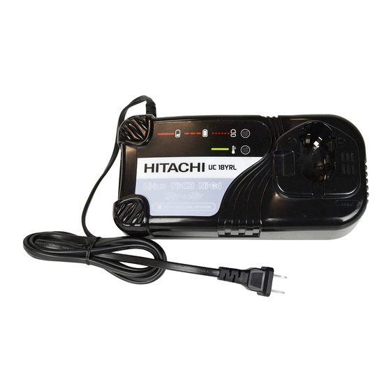
Hitachi UC 18YRL Technical Data And Service Manual
Hide thumbs
Also See for UC 18YRL:
- Safety and instruction manual (40 pages) ,
- Handling instructions manual (57 pages) ,
- Handling instructions manual (50 pages)

Related Manuals for Hitachi UC 18YRL


Summary of Contents for Hitachi UC 18YRL
- Page 1 MODELS UC 18YRL UC 18YFL Hitachi Power Tools TECHNICAL DATA CHARGER UC 18YRL/UC 18YFL SERVICE MANUAL LIST Nos.: UC 18YRL: G845 Nov. 2006 UC 18YFL: G844 SPECIFICATIONS AND PARTS ARE SUBJECT TO CHANGE FOR IMPROVEMENT...
-
Page 2: Table Of Contents
6-1. Safety Instructions ........................8 6-2. Extra Precautions in Sales Promotion ..................9 7. QUESTIONS AND ANSWERS ON MODELS UC 18YRL AND UC 18YFL ....... 10 8. GENERAL PRECAUTIONS ....................... 13 8-1. Models UC 18YRL and UC 18YFL .................... 13 8-2. -
Page 3: Product Name
Hitachi Charger, Models UC 18YRL and UC 18YFL 2. MARKETING OBJECTIVE The new chargers Models UC 18YRL and UC 18YFL are developed to recharge the Hitachi's new lithium-ion batteries. They are also capable of recharging the currently applicable nickel cadmium (Ni-Cd) and nickel metal hydride (Ni-MH) batteries. -
Page 4: Selling Points
• • • • • • • • • • • • (3) Hitachi original charge control mechanism for longer battery life Capable of recharging both nickel cadmium (Ni-Cd), nickel metal hydride (Ni-MH), SUPER nickel metal hydride (SUPER Ni-MH) and Lithium ion (Li-ion) batteries Recharging/discharging cycles of battery (ambient temperature range between 10ûC and 30ûC) -
Page 5: Selling Point Descriptions
4-1-3. Capable of recharging batteries with internal temperatures as high as 60 ûC Each nickel cadmium (Ni-Cd) battery shown in Figs. 2 and 3 incorporates a thermistor. The Models UC 18YRL and UC 18YFL can continue recharging these batteries until the battery temperature reaches 60 ûC. - Page 6 Discriminating resistor 95 ûC thermal protector Discriminating Thermistor resistor Thermistor terminal terminal terminal terminal terminal terminal terminal terminal (Terminal positions) terminal (Terminal positions) Fig. 5 • Ni-MH batteries (14.4 V, 18 V) Fig. 4 • Ni-MH batteries (9.6 to 12 V) •...
- Page 7 4-1-4. 3-way overcharge protection system Overcharge protection is ensured by a (A) V system or dT/dt system (for Ni-MH battery), (B) built-in battery temperature sensor (thermistor) and (C) a timer. Overcharge range Battery voltage Li-ion battery Charger output voltage Battery temperature 55 C dT/dt Li-ion battery Battery temperature 60 C...
- Page 8 (Charging will commence (Green) when the battery is cooled.) NOTE: The Model UC 18YRL cools the overheated battery by the cooling fan during the standby mode. Rechargeable battery temperature range The rechargeable battery temperature ranges are shown in the table below. Overheated batteries should be cooled to the specified temperature before recharging.
-
Page 9: Specifications
Charging time Approx. 45 minutes (for 3.0 Ah) Product weight 0.6 kg Operating ambient temperature range 0 ûC to 40 ûC 5-2. Comparisons with Similar Products HITACHI UC 18YRL UC 18YFL UC 24YFA • Charging time min. (3.0 Ah) (3.0 Ah) Charging voltage 7.2 to 18... -
Page 10: Precautions In Sales Promotion
6-1. Safety Instructions In the interest of promoting the safest and most efficient use of the Model UC 18YRL and UC 18YFL Chargers by all of our customers, it is very important that at the time of sale the salesperson carefully ensures that the buyer seriously recognizes the importance of the contents of the Handling Instructions. -
Page 11: Extra Precautions In Sales Promotion
6-2. Extra Precautions in Sales Promotion The following points must be given during sales promotion. 6-2-1. Charging may not be possible when the battery temperature is high Charging may not be possible if the temperature of the battery is high after it has been exposed to direct sunlight for a long time or immediately after it has been used. -
Page 12: Questions And Answers On Models Uc 18Yrl And Uc 18Yfl
7. QUESTIONS AND ANSWERS ON MODELS UC 18YRL AND UC 18YFL Q1 What are typical charging methods? A1 The most recent electronic charging methods are outlined below. Voltage Method A Method B Stop current detection UC 14YFA dT/dt UC 18YRL... - Page 13 ) to be generated in a short period of time as shown below. This proportionately accelerates degradation of the plates. microcomputer control system was adopted for the Model UC 18YRL and UC 18YFL chargers in order to stop charging immediately before the battery is fully charged, thereby avoiding the generation of oxygen gas.
- Page 14 0ûC to 45ûC 0ûC to 45ûC UC 18YFL - 5 ûC to 55ûC 0ûC to 45ûC 0ûC to 45ûC 0ûC to 45ûC UC 18YRL *Upper limit of the chargeable battery temperature Charger Ni-Cd battery Ni-MH battery SUPER-Ni-MH battery Li-ion battery UC 14YFA 60ûC...
-
Page 15: General Precautions
8. GENERAL PRECAUTIONS 8-1. Models UC 18YRL and UC 18YFL (1) The outer frame consists of case (A) and case (B). Inside the frame, there is the printed circuit board. (2) The printed circuit board consists of the high-frequency power transformer, microcomputer and other electronic devices to permit rapid charging and to protect against overcharging. -
Page 16: Precautions In Disassembly And Reassembly
9. PRECAUTIONS IN DISASSEMBLY AND REASSEMBLY The [Bold] numbers in the descriptions below correspond to the item numbers in the Parts List and exploded assembly diagram for the Model UC 18YRL . 9-1. Disassembly (1) Remove the four Tapping Screws (W/Flange) D3 x 20 [10] and take off Case (A) [3]. -
Page 17: Troubleshooting Guide
10. TROUBLESHOOTING GUIDE 10-1. Troubleshooting Based on Pilot Lamp Indications Phenomenon Typical causes Check procedures Pilot lamp fails to light or flash. (1) Faulty AC cord Refer to trouble mode (A). (2) Blown fuse (3.15 A) on primary side Red pilot lamp does not stay lit (1) Poor connection of (T) or (S) terminal Refer to trouble mode (B). - Page 18 (2) Trouble mode (B) Red pilot lamp does not stay lit (continues to flash) after battery has been connected. Are the connection terminals Remove dirt or of the charger or the battery dirty, deformed, correct abnormality. or otherwise abnormal ? Check with tester.
- Page 19 (3) Trouble mode (C) Pilot lamp remains green (red fails to light) after battery has been connected. Is ambient temperature Conduct charging within within designated range (between designated temperature range. 0 C and 40 C) ? 0 C to 40 C Is the Allow battery to cool prior to battery very...
- Page 20 (4) Trouble mode (D) Pilot lamp flickers red, indicating abnormality. Is the battery Install battey in correct connected in reverse direction. direction ? Is there some sort of conductive foreign Remove foreign matter. matter in the hole where the battery is inserted ? Is the battery short-circuited Replace the battery.
-
Page 21: Standard Repair Time (Unit) Schedules
11. STANDARD REPAIR TIME (UNIT) SCHEDULES Variable 60 min. MODEL Fixed Work Flow UC 18YRL General Assembly Prism Case (A).(B) Cord Fuse Terminal (A) Printed Circuit Board Ass'y UC 18YFL General Assembly Prism Case (A).(B) Fuse Cord Terminal (A) Printed Circuit... - Page 22 Hitachi Power Tools LIST NO. G845 ELECTRIC TOOL PARTS LIST CHARGER 2006 • • Model UC 18YRL (E1)
- Page 23 PARTS UC 18YRL ITEM CODE NO. DESCRIPTION REMARKS USED HITACHI LABEL 321-679 PRISM 326-281 CASE (A).(B) SET 318-262 CORD 318-261 CORD FOR GBR 318-259 CORD FOR USA, CAN 318-260 CORD FOR AUS 326-306 319-781 FUSE (125V-3.15A) 319-780 FUSE (250V-3.15A) 326-285 TERMINAL (A) PRINTED CIRCUIT BOARD ASS’Y 120V...
- Page 24 Hitachi Power Tools LIST NO. G844 ELECTRIC TOOL PARTS LIST CHARGER 2006 • • Model UC 18YFL (E1)
- Page 25 PARTS UC 18YFL ITEM CODE NO. DESCRIPTION REMARKS USED HITACHI LABEL 321-679 PRISM 326-281 CASE (A).(B) SET 318-262 CORD 318-259 CORD FOR USA, CAN 318-260 CORD FOR AUS 318-261 CORD FOR GBR 319-781 FUSE (125V-3.15A) 319-780 FUSE (250V-3.15A) 326-285 TERMINAL (A) PRINTED CIRCUIT BOARD ASS’Y 120V...