
Related Manuals for Sony HDC1500R


Summary of Contents for Sony HDC1500R
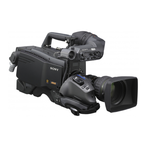
- Page 1 HD COLOR CAMERA HDC1500R HDC1400R HDC1550R HDC1450R OPERATION MANUAL [English] 1st Edition...
- Page 2 AVERTISSEMENT Afin de réduire les risques d’incendie ou For laser-related devices d’électrocution, ne pas exposer cet (HDC1500R/1400R only) appareil à la pluie ou à l’humidité. Afin d’écarter tout risque d’électrocution, garder le coffret fermé. Ne confier l’entretien de l’appareil qu’à un personnel qualifié.
- Page 3 électromagnétiques suivants : E1 (résidentiel), E2 (commercial et industrie légère), E3 (urbain extérieur) et E4 (environnement EMC contrôlé, ex. studio de télévision). Le fabricant de ce produit est Sony Corporation, 1-7-1 Konan, Minato-ku, Tokyo, Japon. Le représentant autorisé pour EMC et la sécurité des produits est Sony Deutschland GmbH, Hedelfinger Strasse 61, 70327 Stuttgart, Allemagne.
-
Page 4: Table Of Contents
PAINT Menu ................46 MAINTENANCE Menu ............51 FILE Menu ................55 DIAGNOSIS Menu ..............57 Using a “Memory Stick” ............58 Specifications............... 59 HDC1500R ................59 HDC1400R ................60 HDC1550R ................61 HDC1450R ................62 Optional Accessories and Related Equipment ......63 Dimensions ................64 Table of Contents... -
Page 5: Overview
HDC1450R covers two video formats. With the mechanism for the viewfinder attachment has been HDC1500R, signal output of 1080/50P and 59.94P from widened. Any difference in weight balance caused by the camera head is also possible via the Dual Link having a different lens attached can be counteracted by interface. - Page 6 Change of hue and decrease in chroma that occur in For details on lenses supporting auto aberration highlighted areas can be compensated. compensation, contact a Sony sales representative or Sony This enables reproduction of natural skin tones under service representative.
-
Page 7: System Configuration
Production of some of the peripherals and related devices shown in the figures has been discontinued. For advice on Easy menu-based setting choosing devices, please contact your Sony dealer or a Selections and settings for viewfinder display items, Sony sales representative. - Page 8 Connection example 1 (HDC1500R/1400R) HDVF-C730W/C950W/550 Viewfinder HKCU1001 HDVF-20A HDVF-200 HKCU1003 BKW-401 Viewfinder HDVF-C30WR Rotation Bracket HDVF-C35W Viewfinder HKCU1005 Zoom Lens HDC1500R/1400R (for ENG/EFP) Optical Fiber Cable HDCU1000 HD Camera “Memory Stick” With HKCU1001 CAC-6 Control Unit or HKCU1003 Return Video Selector...
- Page 9 Connection example 2 (HDC1550R/1450R) HDVF-C730W/C950W /550 Viewfinder HDVF-20A HKCU1001 HDVF-200 HDVF-C30WR BKW-401 Viewfinder HDVF-C35W HKCU1003 Rotation Bracket Viewfinder HDFX100 HKCU1005 Zoom Lens HD Triax HDC1550R/1450R (for ENG/EFP) CCU Adaptor Triax Cable With HKCU1001 HDCU1000 HD Camera “Memory Stick” or HKCU1003 Control Unit Optical Fiber VCT-14...
-
Page 10: Connection Example
+Large Lens Adaptor +HDVF-C730W/C950W Electronic Viewfinder RCP-700/900-series HDC1550R/1450R HD Color Video Camera Remote Control Panel 1) HDC1500R with Large Lens Adaptor attached is illustrated. 2) HDC1500R is illustrated. Maximum cable run with Triax cable Notes The maximum Triax cable length between the •... -
Page 11: Precautions
The white flecks especially tend to be seen Precautions • when operating at a high environmental temperature • when you have raised the master gain (sensitivity) This product has a compensation function and the problem may be alleviated by automatic black balance adjustment Note on laser beams (see page 26). -
Page 12: Locations And Functions Of Parts
Locations and Functions of Parts Accessory Attachments a VF connector b Shoulder strap fitting post c Accessory shoe d Viewfinder left-right positioning ring e Viewfinder front-rear positioning lever and lock knob f Lens cable clamp AT SE RIE S MU LTI FO RM g Lens fixing lever S E R IE S... -
Page 13: Controls And Connectors
The return video 1 signal from the camera control unit is monitored on the viewfinder screen while this button is HDC1500R/1550R pressed. It function the same as the RET 1 button on the You can switch the built-in ND and CC (color temperature... - Page 14 Pressing the left button selects the available ND filters A or B: Selects memory A or B. (clear, 1/4ND, 1/8ND, 1/16ND,1/64ND) in sequence. j DISPLAY switch Pressing the right button selects the available CC filters (cross, 3200K, 4300K, 6300K, 8000K) in sequence. The functions of the DISPLAY switch are as follows: ON: Characters and messages showing the camera settings HDC1400R/1450R...
- Page 15 Front left AT SE RIE S MU LTI FO RM S E R IE S d SHUTTER switch a RET 1 button e INTERCOM LEVEL control b MIC 1 IN connector c MIC power switch f RET 2 button a RET 1 (return video 1) button ON: The electronic shutter is activated.
- Page 16 Shoulder strap fitting post (page 12) Operation panel (page 17, page 18) c CCU connector (HDC1500R/1400R) HDCU/HDFX connector (HDC1550R/1450R) d SDI 1 connector (HDC1500R only) e PROMPTER2 connector (HDC1500R only) Connector panel (page 19) a CAMERA POWER switch f CALL button...
- Page 17 Operation panel SY type: For JN3/JN4/SYL/UC7 (USA, Canada, East Asia and other countries) models (for NTSC areas) For details on the differences among models, see “Overview” on page 5. b RET 1 button and select switch a INTERCOM1 and INTERCOM2 controls and switches c RET 2 button and select switch d LIGHT switch PGM1 control...
- Page 18 European type: For CED (Europe) and E33 (China and South Asia) models (for PAL areas) For details on the differences among models, see “Overview” on page 5. b RET 1 button and select switch a INTERCOM1 and INTERCOM2 controls and switches c RET 2 button and select switch ENG control d LIGHT switch...
- Page 19 AUDIO IN j TEST OUT connector DC IN 10.5-17V f DC IN connector SDI 2 k SDI 2 connector (HDC1500R) SDI connector (HDC1550R/1400R/ 1450R) l AUDIO IN CH1 and CH2 connectors and switches a EARPHONE jack (stereo minijack) h REMOTE connector (8-pin)
- Page 20 To output the analog signal. connected This also supplies the VBS signal, an HD signal nearly AES/EBU (HDC1500R/1400R only): When a digital equal to the signal output from the VF connector, an HD- audio signal is connected (The signal must be in SYNC signal, or an SD-SYNC signal depending on which synchronization with the camera output).
-
Page 21: Preparations
Note Preparations The various parts of the lens used in adjusting the flange focal length are in different positions on different lenses. Refer to the operation manual for the particular lens. Attaching a Lens Adjusting procedure For information on handling lenses, refer to the lens’ Set the iris control to manual, and open the iris fully. - Page 22 Slide the viewfinder left or right to move it into a good viewing position. VF connector Viewfinder stopper Tighten the viewfinder left-right positioning ring. To adjust the position forward or backward Viewfinder front-rear LOCK knob positioning lever Mu lti Fo rm MIC 1 IN connector Slide the viewfinder in the direction of the arrow.
-
Page 23: Attaching The Cable Clamp Belt (Supplied)
position, the arm of the viewfinder rotation bracket will Adjust the front-rear position so that the camera strike the grip. handle does not interfere when you rotate the BKW- 401 arm upwards. Attaching procedure of the BKW-401 Not to interfere Turn the arm of the rotation mechanism assembly of the BKW-401 in the direction of the arrow in the following illustration. -
Page 24: Adjusting The Shoulder Pad Position
Secure the cable clamp belt to the camera, using the Adjusting the Shoulder Pad Position two supplied +B3×8 screws. You can shift the shoulder pad from its center position (factory setting) backward by up to 10 mm (3/8 inch) or forward by up to 25 mm (1 inch). - Page 25 If the pin of the tripod adaptor does not return to Mounting procedure its original position Attach the tripod adaptor to the tripod and secure it After removing the camera, if the pin of the tripod adaptor with the screw. does not return to its original position, hold down the red button and move the lever in the direction of the arrow to return the pin to its original position.
-
Page 26: Adjustments And Settings For Shooting
Automatic adjustment of black balance begins. Adjustments and In automatic adjustment of black balance, both the black set and black balance are adjusted. Settings for Shooting During adjustment, a message like the one in the figure below will be displayed on the viewfinder screen. Adjusting the Black Balance and White Balance ABB:EXECUTING... - Page 27 HDC1500R/1550R To select the ND filter Press the ND filter select button while holding the FILTER LOCAL button depressed. Each press of the select button switches the available ND filters (clear, 1/4ND, 1/8ND, 1/16ND,1/64ND) in sequence. To select the CC filter Press the CC filter select button while holding the FILTER LOCAL button depressed.
-
Page 28: Setting The Electronic Shutter
Push the AUTO W/B BAL switch to WHT and release white balance will be adjusted automatically according to the switch. the filter settings. The adjusted value will be stored in the selected memory. Each memory can store up to five adjusted values, for a total of 10. -
Page 29: Setting The Focus Assist Functions
Setting the shutter mode, and shutter speed in Rotate the MENU SEL knob/ENTER button to align Standard mode the arrow marker ( ) to “TOP” and push on the MENU SEL knob/ENTER button. Push the SHUTTER switch from the ON position to The TOP MENU screen is displayed. -
Page 30
FLICKER: Turn ON/OFF the function to flicker the Rotate the MENU SEL knob/ENTER buttonto align detail signal, which makes it easier to check the the arrow marker ( ) to
and push signal on a CRT screen. on the MENU SEL knob/ENTER button. AREA: To limit the area where to display the detail The ... -
Page 31: Setting The Camera Outputs
The menu pages used for the output settings have been registered to the USER menu at the factory. •• -
Page 32
OUTPUT OUTPUT SIGNAL / OUTPUT SD-SDI Outputting via Dual Link (HDC1500R only) The SDI-1 output is assigned to Link A, SDI-2 output to To output as VBS Link B. Menu page Item Setting Note This function cannot be used when a camera control unit is ... -
Page 33: Viewfinder Screen Status Display
(1, 2, 3, 4, or 5) indicates the ND filter, and the letter (A, B, Displays the shutter/ECS status. Nothing is displayed if the C, D or E) is for the CC filter (HDC1500R/1550R only). electronic shutter is set to OFF. -
Page 34: Menu Operations
The menu page that last operated will be displayed. (If it is <‘!’ IND> function. Display options can be set, using the the first time, the CONTENTS page of the OPERATION menu. (!CC is displayed for HDC1500R/1550R only.) menu will be displayed.) For details, see OPERATION menu <‘!’ IND> (page 41). -
Page 35: Selecting Pages
Available menus The CONTENTS page or the last operated page of the selected menu is displayed. USER menu This menu can include menu pages selected from among Selecting Pages the OPERATION, PAINT, MAINTENANCE, FILE, and DIAGNOSIS menus, for convenience. Changing, adding, and deleting pages can be performed with the USER When selecting a page from a CONTENTS MENU CUSTOMIZE menu. -
Page 36: Setting The Menu Items
Rotate the MENU SEL knob/ENTER button to flip Push on the MENU SEL knob/ENTER button. through the pages. The “?” mark will change back to the arrow marker ), and the new setting will be registered. When the desired page is displayed, push on the MENU SEL knob/ENTER button. -
Page 37
MAINTENANCE knob/ENTER button until the desired page appears,
MAINTENANCE then push on the MENU SEL knob/ENTER button to (HDC1500R) MAINTENANCE select the page. or (HDC1550R/1400R/1450R) Example: When you select the USER 2 EDIT page ... -
Page 38
Turn the MENU SEL knob/ENTER button to move the
arrow marker ( ) to the position where you wish to FLARE move the item then push on the MENU SEL knob/ GAMMA BLK GAM : OFF ENTER button. KNEE WHT CLIP: DETAIL... - Page 39 If a different page is displayed, turn the MENU SEL The EDIT FUNCTION screen appears. knob/ENTER button until the EDIT PAGE screen appears, then push on the MENU SEL knob/ENTER Select “DELETE” then push on the MENU SEL knob/ button to select the page. ENTER button.
-
Page 40: Menu List
ZOOM ON, OFF DISP LEFT LEFT, RIGT FOCUS ON, OFF Valid only when a serial lens is used ON, OFF ON, OFF Valid with HDC1500R/1550R only 5600K ON, OFF IRIS ON, OFF WHITE ON, OFF D.EXT ON, OFF GAIN ON, OFF... - Page 41 [IND] ON ON, OFF Note [NORMAL] 59.94i or HDC1500R/1550R: CC is available for 50i (HDC1400R CED/ 59.94i, 29.97PsF, 50i, HDC1500R/1550R only. E33 and HDC1450R 25PsF, 24PsF, 23.98PsF, CED models) 59.94P, 50P HDC1400R JN3/JN4 and HDC1450R UC7 models: 59.94i, 59.94P HDC1400R CED/E33 and...
-
Page 42
Page title Item Default Settings Remarks
VF DETAIL ON, OFF (U02) 0 to 100% CRISP –99 to +99 FREQUENCY 9M, 14M, 18M FAT MODE ON, OFF FLICKER ON, OFF AREA 100% 100%, 70%, 60%, 50%, 40% ZOOM LINK 0%, 25%, 50%, 75%, 100% COLOR DETAIL ON, OFF... -
Page 43
Page title Item Default Settings Remarks
GAIN [L] 0 dB –3, 0, 3, 6, 9, 12 dB (U09) [M] 6 dB –3, 0, 3, 6, 9, 12 dB [H] 12 dB –3, 0, 3, 6, 9, 12 dB ASSIGNABLE OFF, RETURN1 SW, JN3/JN4/SYL/UC7 models... -
Page 44
Page title Item Default Settings Remarks
LENS VTR S/S RETURN2 SW OFF, RETURN1 SW, JN3/JN4/SYL/UC7 models (U10) RETURN2 SW, INCOM1, only. INCOM2 Assign a function to the VTR START/STOP switch on the mounted lens. RETURN2 SW OFF, RETURN1 SW, CED/E33 models only. - Page 45 Page title Item Default Settings Remarks INTERCOM1 MIC DYNAMIC DYNAMIC, CARBON, (U13) MANUAL LEVEL (–60 dB) –60 dB, –50 dB, –40 dB, Settings in ( ): With DYNAMIC –30 dB, –20 dB or CARBON (cannot be changed) 0 dB –6 dB, 0 dB, +6 dB Input gain POWER...
-
Page 46: Paint Menu
Page title Item Default Settings RemarksEARPHONE SEPARATE SEPARATE, MIX RECEIVE SELECT INTERCOM LEFT RIGHT, LEFT, BOTH, - - - JN3/JN4/SYL/UC7 models only LEFT RIGHT, LEFT, BOTH, - - - CED/E33 models only PROD LEFT RIGHT, LEFT, BOTH, - - - CED/E33 models only PGM1 RIGHT... - Page 47 Menu page Item⁄ Default Settings Remarks
-
Page 48
Menu page Item⁄ Default Settings Remarks
[R] [G] [B] [M] R, G, B, and M (master) values K POINT –99 to +99 can be independently set. Absolute values are displayed in K SLOPE –99 to +99 ABS mode except for M (master). KNEE ON, OFF KNEE MAX... -
Page 49
Menu page Item⁄ Default Settings Remarks
SKIN DTL ON, OFF SKIN GATE OFF, 1, 2, 3, (MAT) 1, 2, 3: Skin gate can be set to ON for the specified channel only. (MAT): Displayed when GATE of is ON. Highlighted: ABS (Absolute) mode Skin tone detail function can be (ON) OFF OFF... -
Page 50
Menu page Item⁄ Default Settings Remarks
SHUTTER ON, OFF JN3/JN4/SYL/UC7 59.94i: 1/100, 1/125, 1/250, Step shutter setting models: 1/500, 1/1000, 1/2000 Note 1/100 (sec) 50i: 1/60, 1/125, 1/250, There are some formats that CED/E33 models: 1/500, 1/1000, 1/2000 cannot be selected on 1/60 (sec) 29.97PsF: 1/40, 1/60, 1/120, HDC1450R/1400R. -
Page 51: Maintenance Menu
MAINTENANCE Menu Menu page Item⁄ Default Settings RemarksAUTO BLACK Execute by ENTER. AUTO WHITE Execute by ENTER. AUTO LEVEL Execute by ENTER. AUTO WHITE SHADING Execute by ENTER. AUTO BLACK SHADING Execute by ENTER. TEST OFF, SAW, 3STEP, 10STEP ... - Page 52 ON, OFF Valid with CCU connected CAM CALL ON, OFF Valid with CCU connected
-
Page 53
–127 to +127 H-PHASE –127 to +127
OUTPUT MAIN MAIN, VF, LINK-B, RET, SD- The signal selected for (HDC1500R) (U18) OUTPUT SIGNAL of is output in SD-SDI mode. (PWR SAVE) Displayed in POWER SAVE mode only... - Page 54 5 M/D/Y 6 M/D FILTER WHT MEM ON, OFF Set to ON to use independent white memory at each CC filter position (HDC1500R/1550R only). F NO. DISP CONTROL CONTROL, RETURN Select the iris indication on the panel when AUTO IRIS is off:...
-
Page 55: File Menu
FILE Menu Five types of files can be used for easy adjustments of the For the specific items included in these files, refer to the camera; Operator, Reference, Scene, OHB, and Lens. Maintenance Manual. You can store the items set with the OPERATION menu and customized USER menu in the Operator file. -
Page 56
Menu page Item⁄ Default Settings Remarks
STORE FILE Execute by ENTER. To store the current settings of the reference file items in the reference file in internal memory. STANDARD Execute by ENTER. To read the standard values in the reference file in internal memory. -
Page 57: Diagnosis Menu
With CCU connected only SIGNALOK, NG OK, NG OK, NG OK, NG OK, NG OK, NG OK, NG OK, NG HDC1500R/1400R only OK, NG HDC1550R/1450R only Vx.xx R IT Vx.xx Vx.xx Vx.xx Vx.xx Vx.xx HDC1550R/1450R only Vx.xx... -
Page 58: Using A "Memory Stick
• To prevent data loss, make backups of data frequently. In Access lamp Memory Stick no event will Sony be liable for any loss of data. • Unauthorized recording may be contrary to the provisions of copyright law. When you use a “Memory Stick”... -
Page 59: Specifications
Sony Corporation. • “Memory Stick PRO” and HDC1500R trademarks of Sony Corporation. • “Memory Stick PRO Duo and are trademarks of Sony Corporation. General • “MagicGate” and are trademarks of Sony Corporation. Power requirements 240 V AC, 1.4 A (max.) 180 V DC, 1.0 A (max.) -
Page 60: Hdc1400R
20-pin (1) Attention concernant le câble optique/électrique MIC 1 IN XLR 3-pin, female (1) composite: AUDIO IN CH1, CH2 Pour la connexion entre l’unité de commande de caméra et XLR 3-pin, female (1 each) une caméra, utilisez un câble optique/électrique composite For MIC: −60 dBu (may be selected avec connecteurs spécifiés dans ce manuel pour assurer la up to −20 dBu by menu or... -
Page 61: Hdc1550R
Optical system specifications Pour les utilisateurs aux Etats-Unis, au Canada, en Europe, à l’Australie, et à la Nouvelle-Zélande Spectral system F1.4 prism Connecteurs pour les câbles optiques/électriques Built-in optical filters1: clear composites: 2: 1/4 ND • LEMO PUW.3K.93C.TLCC96 (au connecteur ®... -
Page 62: Hdc1450R
Electrical characteristics Supplied accessories Sensitivity f10.0 with 1080/59.94i Operation manual (1) f11.0 with 1080/50i Cable clamp belt (1 set) (at 2000 lx with 89.9% reflectivity) Switch label 1, 2 (1 each) Typical −56 dB/−64 dB (NS MAX) Image S/N Horizontal resolution Design and specifications are subject to change without 1000 TV lines (at center of screen) notice. -
Page 63: Optional Accessories And Related Equipment
Note maximum Always verify that the unit is operating properly before It may be limited depending on the use. SONY WILL NOT BE LIABLE FOR DAMAGES load and input conditions. OF ANY KIND INCLUDING, BUT NOT LIMITED BNC type (1) -
Page 64: Dimensions
Dimensions HDC1500R/1400R Unit: mm (inches) 135 (5 362 (14 HDC1550R/1450R Unit: mm (inches) 156 (6 362 (14 Specifications... - Page 65 The material contained in this manual consists of information that is the property of Sony Corporation and is intended solely for use by the purchasers of the equipment described in this manual. Sony Corporation expressly prohibits the duplication of any portion of this manual or the use thereof for any...
- Page 66 HDC1500R (JN4/SYL/CED/E33) Sony Corporation HDC1400R (JN3/JN4/CED/E33) HDC1550R (UC7/CED) Printed in Japan HDC1450R (UC7/CED) 2009.02 13 4-140-776-01(2) © 2009...