
Related Manuals for Sony FCB-EX2700P


Summary of Contents for Sony FCB-EX2700P
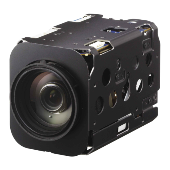
- Page 1 A-ES4-100-11(1) Color Camera Module Technical Manual FCB-EX2700/EX2700P 2013 Sony Corporation...
-
Page 2: Table Of Contents
Table of Contents Features ................3 Precautions ............... 4 Locations of Controls ............5 Basic Functions ..............6 Overview of Functions ..............6 Eclipse ....................22 Spectral Sensitivity Characteristics .......... 22 Key Switch Circuitry ............... 23 Key Function Specifications ............24 Initial Settings, Custom Preset and Backup ...... -
Page 3: Features
Overview Features T he high resolution and high sensitivity images can E -FLIP and Mirror Image functions be obtained using “Super-HAD CCD II” CCD of A larm function with adjustable detection zones approx. 480,000 (NTSC) 976 (H) × 494 (V) or approx. A djustable AE response speed 570,000 (PAL) 976 (H) × 582 (V) effective pixels. A CCD for shooting a wide dynamic range is employed to perform progressive or interlaced With consideration given environmental protection, scanning, and images with a wide dynamic range are this module is designed to operate with low power obtained by a newly developed image signal processor consumption and also incorporates lead-free and (Wide Dynamic Range function). Furthermore, the halogen-free circuit boards. -
Page 4: Precautions
Overview Precautions Software Phenomena specific to CCD image sensors Use of the demonstration software developed by Sony The following phenomena that may appear in images Corporation or use of the software with customer are specific to CCD (Charge Coupled Device) image developed application software may damage hardware, sensors. They do not indicate malfunctions. the application program or the camera. Sony Corporation White flecks is not liable for any damages under these conditions. Although the CCD image sensors are produced with high-precision technologies, fine white flecks may be Operation generated on the screen in rare cases, caused by cosmic Start the camera control software on your computer rays, etc. after you turn on the camera and the image is displayed. This is related to the principle of CCD image sensors and is not a malfunction. Operation and storage locations The white flecks especially tend to be seen in the following cases: Do not shoot images that are extremely bright (e.g.,... -
Page 5: Locations Of Controls
Locations of Controls Locations of Controls Front Back Bottom Lens TELE button Tripod screw hole CN500 jack (for Y/C output) WIDE button When a tripod is used, use 7 mm ( in.) or less screw to attach it to the ... -
Page 6: Basic Functions
Basic Functions Basic Functions Overview of Functions In general P ower On/Off VISCA commands are the basis of camera control. Powers the camera on and off. When the power is off, the camera is able to accept only the lowest level of VISCA Commands; the display and other features are Timing Chart turned off. As VISCA Command processing can only be carried I /F Clear out one time in a Vertical cycle, it takes the maximum Clears the Command buffer of the FCB camera. 1V cycle time for an Acknowledge/Completion to be Clearing the buffer can also be carried out from the returned. control application software when the power is on. If the Command Acknowledge/Completion communication time can be cut shorter than the 1V A ddress Set cycle time, then every 1V cycle can receive a VISCA is a protocol, which normally supports a daisy Command. chain of up to seven connected cameras via RS-232C interface. In such cases, the address set command can be used to assign addresses from 1 to 7 to each of the General Commands seven cameras, allowing you to control the seven cameras with the same personal computer. - Page 7 Basic Functions Zoom Focus The FCB camera employs a 40× optical zoom lens Focus has the following modes, all of which can be set combined with a digital zoom function; this camera using VISCA Commands. allows you to zoom up to 480×. A uto Focus Mode The Auto Focus (AF) function automatically adjusts O ptical 40×, f = 3.06 mm to 122.4 mm (F 1.6 to F 4.6) the focus position to maximise the high frequency content of the picture in a center measurement area, The horizontal angle of view is approximately 60 taking into consideration the high luminance and degrees (wide end) to 1.6 degrees (tele end). strong contrast components. Digital Zoom enlarges the center of the subject by - Normal AF Mode expanding each image in both the vertical and This is the normal mode for AF operations. horizontal directions. When 480× zoom is used, the - Interval AF Mode number of effective picture elements in each direction The mode used for AF movements carried out at reduces to and the overall resolution deteriorates. particular intervals. The time intervals for AF movements and for the timing of the stops can be You can activate the zoom in the following three ways. set in one-second increments using the Set Time B y pressing the TELE or WIDE buttons on the Command. The initial value for both is set to five camera itself seconds.
-
Page 8: White Balance
Basic Functions S hutter Priority White Balance Variable Shutter Speed, Auto Iris and Gain White Balance has the following modes, all of which (1/1 to 1/10,000 sec., 16 high-speed shutter speeds can be set using VISCA Commands. plus 6 low-speed shutter speeds) 1) Flicker can be eliminated by setting shutter to A uto White Balance 1/100s for NTSC models used in countries with a 50 Hz This mode computes the white balance value output power supply frequency using color information from the entire screen. It 1/120s for PAL models used in countries with a 60 Hz outputs the proper value using the color temperature power supply frequency radiating from a black subject based on a range of I ris Priority values from 3000 to 7500K. Variable Iris (F1.6 to Close, 18 steps), Auto Gain and This mode is the factory setting. Shutter speed A TW M anual Auto Tracing White balance (2000 to 10000K) Variable Shutter, Iris and Gain I ndoor... - Page 9 Basic Functions AE – Iris priority Data Iris Gain Data Iris Gain The iris can be set freely by the user to 18 steps F1.6 +28 dB F2.4 0 dB between F1.6 and Close. F1.6 +26 dB F2.8 0 dB The gain and shutter speed are set automatically, F1.6 +24 dB F3.4 0 dB according to the brightness of the subject. F1.6 +22 dB 0 dB F1.6 +20 dB F4.8 0 dB Data Setting value Data Setting value F1.6 +18 dB F5.6...
- Page 10 Basic Functions Exposure Compensation Aperture Control Exposure compensation is a function which offsets the Aperture control is a function which adjusts the internal reference brightness level used in the AE enhancement of the edges of objects in the picture. mode, by steps of 1.5 dB. There are 16 levels of adjustment, starting from “no The reference brightness is 0. enhancement. ” When shooting text, this control may help by making them sharper. Data Step Setting value +10.5 dB +9 dB Back Light Compensation +7.5 dB When the background of the subject is too bright, or +6 dB when the subject is too dark due to shooting in the AE +4.5 dB mode, back light compensation will make the subject +3 dB appear clearer. +1.5 dB 0 dB –1 –1.5 dB Wide Dynamic Range Mode (WD) –2 –3 dB –3...
-
Page 11: Noise Reduction
Basic Functions Supplemental explanation Noise Reduction In the WD mode, there is a restriction as follows. The NR (Noise Reduction) function removes noise W hen 60p/50p is output, the information amount is (both random and non-random) to provide clearer equivalent to 30p/25p because the long exposure images. By combining 2D filtering according to signal and short exposure signal are combined. brightness and image color, and 3D filtering according As for during the VE mode and interlace output, the to noise caused by motion and time difference, lower- information amount will be 60p/50p. noise images can be obtained for the corresponding As for the VE mode, the information amount of 60p image brightness of a moving subject. can be used because it performs processing with a This function has six steps: levels 1 to 5, plus off. single image without a change in the frame rate even Level 1 applies to subject motion mainly using 2D filter when the progressive mode CCD reading is effects. With level 5, 2D and 3D filter effects are performed. maximized, providing the lowest-noise images, When 30/25 fps is output, the WD mode cannot be ON. Use the VE although moving subjects may show trails. - Page 12 Basic Functions Color Enhancement Temperature Reading Function A captured color image is converted to 256 levels of The conversion value (hex) of the temperature sensor gray, and the binarization process is performed to built into to the camera can be read by using a query convert all gray levels brighter than the threshold value command. The conversion value has an error of ±3˚C, to white, and all gray levels darker than the threshold and because the temperature sensor is inside the value to black. (Any value can be set for the threshold camera, this value is not the ambient temperature. Use level and hysteresis width.) Furthermore, any color can it as a reference value. be assigned to each of the negative and positive. Slow shutter – Auto/Manual Note Flickering in images during color enhancement is not an indication When set to “Auto, ” ensures that the slow shutter is set of a camera malfunction. It can be reduced with the threshold level, automatically when the brightness drops. Effective only hysteresis width, and edge enhancement (aperture) settings. when the AE mode is set to “Full Auto. ” Set to “Slow Shutter Manual” at shipment. Grayscale image Note (256 levels) The Slow Shutter Auto function is not available in WD mode.
- Page 13 Basic Functions Camera ID When Auto Slow Shutter is Off (initial setting) The ID can be set up to 65,536 (0000 to FFFF). As this will be memorized in the nonvolatile memory inside, Shutter 1/60 sec IRIS data will be saved regardless of whether it has been OPEN backed up. GAIN IRIS Effect ICR ON SHUTTER It consists of the following functions. N eg. Art: Negative/Positive Reversal Dark Bright B lack White: Monochrome Image ICR OFF ON Others When Auto Slow Shutter is On E-FLIP...
-
Page 14: Motion Detection
Basic Functions Zoom Limit: 50 (Wide end), 51 (Tele end) R /B Gain The Wide and Tele zoom limits can be set. A perture Control E-Zoom Max: 52 I CR Shoot On/Off The maximum digital zoom limit can be specified W D On/Off (default is ×12). StableZoom: 53 W D Parameter The StableZoom command can be enabled and D efog On/Off disabled with this command. FocusTrace: 54 Custom Preset When zoom speed is given priority, using the As with the position preset function, the camera ZoomDirect command changes focus at high shooting conditions can be stored and recalled. The speed (although the image may be blurred because settings are recalled when the power is turned on. focus is not tracked). For example, the focus For setting items, see the “Initial Settings, Custom Preset and Backup” transition time from Wide to Tele ends, which section on page 26. - Page 15 Basic Functions Note Noise may occur when performing phase adjustment with the Line Lock mode, although it should disappear when switching to Frequency Lock mode for external sync. Because V-lock synchronization is a simple synchronization method, color signals like a VBS “Genlock” signal cannot be synchronized. 1) In V-lock synchronization, the camera makes a V-lock pulse (VL-PULSE) which synchronizes to the commercial power supply and uses it as the external synchronization input signal of the camera, using the fact that the V cycle (59.94 Hz vertical synchronization signal) and the frequency of the commercial power supply (60 Hz). The synchronous signal of the camera will automatically sychronizes to the VL-PULSE in the camera. Synchronization methods Internal and external synchronization are available; VISCA Commands allow you to switch between them. I nternal synchronization An internal vibrator inside the camera generates a synchronizing signal as a basic oscillator. NTSC=59.94 Hz PAL=50 Hz E xternal synchronization (V-Lock...
- Page 16 Basic Functions Privacy Zone Masking Function Privacy Zone masking protects private objects and areas such as house windows, entrances, and exits which are within the camera’s range of vision but not subject to surveillance. Privacy zone masking can be masked on the monitor to protect privacy. Features M ask can be set on up to 24 places according to Pan/Tilt positions. M ask can be displayed on 8 places per screen simultaneously. P rivacy Zones are displayed according to priority in alphabetical order. I ndividual on/off zone masking settings. S elected two colors can be individually set for each of 24 privacy zones. I nterlocking control with zooming. I nterlocking control with Pan/Tilt. N on-interlocking control with Pan/Tilt. Timing chart 8x 01 ..FF (Mask Setting Command) Setting command is executed at this timing.
- Page 17 Basic Functions Privacy Zone Setting Command List Command Set Command Command Packet Comments CAM_PrivacyZone SetMask 8x 01 04 76 mm nn Setting Mask(Size) 0r 0r 0s 0s FF See “mm: Mask setting list”, “nn: Setting”, and “pp: x, qq:y, rr: w, ss: h” in “Parameters” on page 18. Display 8x 01 04 77 pp pp pp pp FF Setting Mask Display On/Off See “pp pp pp pp: Mask bit” in “Parameters” on page 18. pp pp pp pp: Mask setting (0: OFF, 1: ON) SetMaskColor 8x 01 04 78 pp pp pp pp qq rr FF Setting Color of Mask See “pp pp pp pp: Mask bit” and “qq, rr: Color code” in “Parameters” on page 18. qq: Color setting when setting the Mask bit to 0 rr: Color setting when setting the Mask bit to 1 SetPanTiltAngle 8x 01 04 79 0p 0p 0p 0q 0q 0q FF Setting Pan/Tilt Angle See “Setting pan/tilt angle” in “Parameters” on page 18. ppp: Pan, qqq: Tilt SetPTZMask 8x 01 04 7B mm 0p 0p 0p Setting the direct position of Pan/Tilt/Zoom...
- Page 18 Basic Functions Parameters nn:Setting mm: Mask setting list Mask Name mm (Hex) Mask Name mm (Hex) Setting Mask_A Mask_M Resetting the zone size (the value of w,h) for the existing mask. Mask_B Mask_N Setting newly the zone size (the value of w,h). Mask_C Mask_O Mask_D Mask_P Mask_E Mask_Q pp: x, qq: y, rr: w, ss: h Mask_F Mask_R Mask_G Mask_S Mask_H...
- Page 19 Basic Functions Comments: Two different color masks can be chosen. Details of Setting Commands The colors can be chosen from among 14 colors Set Mask including the possibility for semi-transparency of Command: 8x 01 04 76 mm nn 0r 0r 0s 0s FF each color. Therefore two colors from among the Parameter: total of 29 colors including mosaic can be individually set for each of 24 privacy zones. Setting Mask If the bit of parameter (pp pp pp pp) is set to “0”, See “mm: Mask setting list” in “Parameters” on page 18. mask color will be “qq” color (Color code). If the Selects new setting or resetting for the zone. bit of parameter (pp pp pp pp) is set to “1”, the See “nn: Setting” in “Parameters” on page 18. mask color will be “rr” color (Color code). Sets the half value “w” of the Mask Width. Sets the half value “h” of the Mask Height. Example: 8x 01 04 78 00 00 00 03 10 07 FF See “pp: x, qq: y, rr: w, ss: h” in “Parameters” on page 18. The mask color setting of Mask_A and Mask_B is Comments: To set the mask, first display the object at White (color code 07h), and the mask color of the the center of the screen. When “nn” is set to 1, the other Mask (C to X) is semi-transparent Black current Pan/Tilt/Zoom position is recorded in (color code 10h). internal memory. When “nn” is set to 0, the Pan/Tilt/Zoom position Set Pan/Tilt Angle in memory is not changed.
- Page 20 Basic Functions Motion Detection Function Non Interlock Mask Command: 8x 01 04 6F mm 0p 0p 0q 0q 0r 0r 0s 0s This function instructs the camera to detect movement Parameter: within the monitoring area and then send an alarm signal automatically. Setting Mask The detected signal goes out through the serial See “mm: Mask setting list” in “Parameters” on page 18. communication line (VISCA command). Sets the center position “x” of the Mask on screen. Sets the center position “y” of the Mask on screen. Sets the half value “w” of the Mask Width. Features Sets the half value “h” of the Mask Height. See “pp: x, qq: y, rr: w, ss: h” in “Parameters” on page 18. Y ou can set a frame for the detection range of 12 (horizontally) × 8 (vertically) blocks. Comments: Mask does not interlock with pan/tilt. Y ou can set up to four frames. The limitations of parameters are as follows. W hen the motion is detected in the set frame, the (hexadecimal representation) Alarm Replay VISCA command is sent. x: ±50h T he threshold level for detection can be set (common ...
- Page 21 Basic Functions Sending Alarms W hen multiple motions are detected or motion is detected in another frame within the set interval W hen motion is detected, the Alarm Replay following the original time the alarm was issued, command is issued via the serial command (VISCA) another alarm command is not issued. communication line. W hen motion is detected after the interval time elapsed, the alarm is issued again. Alarm issue Alarm issue Alarm issue Alarm issue Interval Interval Interval Alarm interval Motion is Motion is Motion is Motion is Motion is Motion is Motion is...
-
Page 22: Eclipse
Basic Functions Eclipse When designing the housing, refer to the dimensional allowance as shown in the figure below. Spectral Sensitivity Characteristics 1000 WaveLength[nm] Use the graph as a reference value. (We can not guarantee these values.) This data is measured when the IR cut filter is removed and the characteristics of the lens and optical source characteristics are ignored. -
Page 23: Key Switch Circuitry
Basic Functions Key Switch Circuitry The circuitry shown below is an example. Note that all switches in the figure do not function in all models. For more information, refer to the command list, check functions on the camera, or contact your Sony dealer. The CN101 is connected to the FCB camera main unit. -
Page 24: Key Function Specifications
Basic Functions Key Function Specifications Classification Name Function Button operation Mode display ZOOM WIDE FAST Move ZOOM to WIDE side quickly. Pressing repeatedly allowed. ZOOM bar displayed for 3 s. WIDE SLOW Move ZOOM to WIDE side slowly. Pressing repeatedly allowed. ZOOM bar displayed for 3 s. TELE FAST Move ZOOM to TELE side quickly. Pressing repeatedly allowed. ZOOM bar displayed for 3 s. TELE SLOW Move ZOOM to TELE side slowly. Pressing repeatedly allowed. ZOOM bar displayed for 3 s. FOCUS AF ON/OFF Switch between Auto Focus and Manual Focus. Switch between Auto and Manual F indication Manual. NEAR Move focus to NEAR side in Manual Focus Pressing repeatedly allowed. - Page 25 Basic Functions Classification Name Function Button operation Mode display FEATURE FREEZE Capture still image. Switch on/off. CAPTURE indication LR REVERSE Horizontal reversal Switch on/off. Horizontal reversal indication E-FLIP Turn upside down Switch on/off. Turn upside down mark BLACK & Black-and-white output Switch on/off. B&W display WHITE NEGA ART Negative art output Switch on/off. Neg Art display MUTE Muting video output Switch on/off. No display DISPLAY DISPLAY Display Switch on/off. Display/no display TITLE Title setting...
-
Page 26: Initial Settings, Custom Preset And Backup
Basic Functions Initial Settings, Custom Preset and Backup Initial settings for the various functions of the FCB camera are indicated in the “Initial settings” column. The “Custom preset” column indicates whether the custom preset function can be used to store the settings. The function enables the stored settings to be recalled automatically when the camera is turned on. The “Back up at standby” column indicates whether the data is preserved even when the camera is powered OFF. Custom Back up Mode/Position setting Initial settings preset at standby Zoom Position Wide end D-Zoom On/Off D-Zoom Separate/Combine Combine D-Zoom Position Focus Position — Focus Auto/Manual Auto ... - Page 27 Basic Functions Custom Back up Mode/Position setting Initial settings preset at standby Camera Memory Same as the initial value setting Display On/Off Mute On/Off Auto ICR Alarm On/Off Image Stabilizer On/Off/Hold Defog On/Off NR Level Gain Limit — Color Enhancement On/Off ...
-
Page 28: Mode Condition
Basic Functions... - Page 29 Basic Functions...
- Page 30 Basic Functions...
-
Page 31: Command List
Command List Command List Overview of VISCA VISCA /RS-232C Commands In VISCA, the device outputting commands, for example, a computer, is called the controller. The device receiving the commands, an FCB camera is This Manual outlines an RS-232 control protocol and called the peripheral device. In VISCA, up to seven command list for certain Sony cameras from which peripheral devices like the FCB camera can be control software can be developed. connected to one controller using communication THIS CONTROL PROTOCOL AND COMMAND conforming to the RS-232C standard. The parameters LIST IS PROVIDED BY SONY ON AN “AS-IS BASIS” of RS-232C are as follows. WITHOUT WARRANTY OF ANY KIND. SONY C ommunication speed: 9.6 kbps/19.2 kbps/38.4 kbps DOES NOT WARRANT ANY PARTICULAR RESULT D ata bits : 8 FROM THE USE OF THIS CONTROL PROTOCOL S tart bit : 1 AND COMMAND LIST AND DISCLAIMS AND S top bit : 1 EXCLUDES ALL WARRANTIES. EXPRESS OR N on parity ... - Page 32 Command List VISCA Communication assigned address 2 is 82H. In the command list, as the header is 8X, input the address of the camera at X. The Specifications header of the reply packet from the camera assigned address 1 is 90H. The packet from the camera assigned address 2 is A0H. VISCA packet structure Some of the commands for setting cameras can be sent to all devices at one time (broadcast). In the case of The basic unit of VISCA communication is called a broadcast, the header should be hexadecimal 88H. packet. The first byte of the packet is called the header When the terminator is FFH, it signifies the end of the and comprises the sender’s and receiver’s addresses. For packet. example, the header of the packet sent to the FCB camera assigned address 1 from the controller (address 0) is hexadecimal 81H. The packet sent to the camera Packet (3 to 16 bytes) Terminator Message (1 to 14 bytes) Header Byte 1 Byte 2 Byte 3 Sender’s address...
- Page 33 Command List Responses for commands and inquiries Command execution cancel To cancel a command which has already been sent, Acknowledge message send the Cancel command as the next command. To Returned by the FCB camera when it receives a cancel one of any two commands which have been command. No Acknowledge message is returned for sent, use the cancel message. inquiries. Cancel Packet Note Completion message Cancel 8X 2Y FF Y = socket number Returned by the FCB camera when execution of X = 1 to 7: FCB camera address, Y = socket number commands or inquiries is completed. In the case of An error message will be returned for this command, inquiry commands, it will contain reply data for the...
- Page 34 GGGG = Vender ID (0020: Sony) HHHH = Model ID 0477: FCB-EX2700 0478: FCB-EX2700P JJJJ = ROM revision KK = Maximum socket #(02) X = 1 to 7: FCB camera address (For inquiry packet) X = 9 to F: FCB camera address +8 (For reply packet)
- Page 35 Command List VISCA Command/Acknowledge Protocol Command Command Message Reply Message Comments General Command 81 01 04 38 02 FF Returns Acknowledge when a command has 90 41 FF (Acknowledge)+90 51 FF (Example) (Completion) been accepted, and Completion when a 90 42 FF 90 52 FF command has been executed. 81 01 04 38 FF 90 60 02 FF (Syntax Error) Accepted a command which is not supported (Example) or a command lacking parameters. 81 01 04 38 02 FF 90 60 03 FF There are two commands currently being (Example) (Command Buffer Full) executed, and the command could not be accepted. 81 01 04 08 02 FF 90 61 41 FF Could not execute the command in the (Example) (Command Not Executable) current mode. 90 62 41FF Inquiry Command 81 09 04 38 FF 90 50 02 FF (Completion) Acknowledge is not returned for the inquiry...
- Page 36 Command List VISCA Camera-Issued Messages Acknowledge/Completion Messages Command Messages Comments Acknowledge z0 4y FF Returned when the command is accepted. (y:Socket No.) Completion z0 5y FF Returned when the command has been executed. (y:Socket No.) z = Device address + 8 Error Messages Command Messages Comments Syntax Error z0 60 02 FF Returned when the command format is different or when a command with illegal command parameters is accepted. Command Buffer Full z0 60 03 FF Indicates that two sockets are already being used (executing two commands) and the command could not be accepted when received. Command Canceled z0 6y 04 FF Returned when a command which is being executed in a socket specified (y:Socket No.) by the cancel command is canceled. The completion message for the command which is being executed is not returned. No Socket z0 6y 05 FF Returned when no command is executed in a socket specified by the (y:Socket No.) cancel command, or when an invalid socket number is specified.
-
Page 37: Fcb Camera Commands
Command List FCB Camera Commands Command List (1/6) Command Set Command Command Packet Comments AddressSet Broadcast 88 30 01 FF Address setting IF_Clear Broadcast 88 01 00 01 FF I/F Clear CommandCancel — 8x 2p FF p: Socket No. (=1 or 2) CAM_Power 8x 01 04 00 02 FF Power ON/OFF 8x 01 04 00 03 FF CAM_Zoom Stop 8x 01 04 07 00 FF — Tele(Standard) 8x 01 04 07 02 FF Wide(Standard) 8x 01 04 07 03 FF Tele(Variable) 8x 01 04 07 2p FF p=0 (Low) to 7 (High) Wide(Variable) 8x 01 04 07 3p FF... - Page 38 Command List Command List (2/6) Command Set Command Command Packet Comments CAM_WB Auto 8x 01 04 35 00 FF Normal Auto Indoor 8x 01 04 35 01 FF Indoor mode Outdoor 8x 01 04 35 02 FF Outdoor mode One Push WB 8x 01 04 35 03 FF One Push WB mode 8x 01 04 35 04 FF Auto Tracing White Balance Manual 8x 01 04 35 05 FF Manual Control mode One Push Trigger 8x 01 04 10 05 FF One Push WB Trigger Outdoor Auto 8x 01 04 35 06 FF Outdoor auto Sodium Lamp Auto 8x 01 04 35 07 FF Auto including sodium lamp source Sodium Lamp 8x 01 04 35 08 FF Sodium lamp source fixed mode CAM_RGain Reset...
- Page 39 Command List Command List (3/6) Command Set Command Command Packet Comments CAM_ExpComp 8x 01 04 3E 02 FF Exposure Compensation ON/OFF 8x 01 04 3E 03 FF Reset 8x 01 04 0E 00 FF Exposure Compensation Amount Setting 8x 01 04 0E 02 FF Down 8x 01 04 0E 03 FF Direct 8x 01 04 4E 00 00 0p 0q FF pq: ExpComp Position CAM_Backlight 8x 01 04 33 02 FF Back Light Compensation ON/OFF 8x 01 04 33 03 FF CAM_SpotAE 8x 01 04 59 02 FF Spot Automatic Exposure Setting 8x 01 04 59 03 FF Position 8x 01 04 29 0p 0q 0r 0s FF pq: X (0 to F), rs: Y (0 to F) CAM_AE_Response DIRECT 8x 01 04 5D pp FF Automatic Exposure Response Setting (01 to 30) CAM_WD 8x 01 04 3D 02 FF WideD ON/OFF 8x 01 04 3D 03 FF...
- Page 40 Command List Command List (4/6) Command Set Command Command Packet Comments CAM_AutoICR 8x 01 04 51 02 FF Auto ICR mode On/Off 8x 01 04 51 03 FF Threshold 8x 01 04 21 00 00 0p 0q FF pq: ICR ON OFF threshold level CAM 8x 01 04 31 02 FF Auto ICR switching Alarm ON/OFF _AutoICRAlarmReply 8x 01 04 31 03 FF (Reply) y0 07 04 31 02 FF ICR OFF ON y0 07 04 31 03 FF ICR ON OFF CAM_Stabilizer 8x 01 04 34 02 FF Hand shake correction ON/OFF 8x 01 04 34 03 FF Hold 8x 01 04 34 00 FF Hand shake correction hold CAM_Memory Reset 8x 01 04 3F 00 0p FF p: Memory Number (=0 to 5) 8x 01 04 3F 01 0p FF Recall 8x 01 04 3F 02 0p FF CAM_CUSTOM...
- Page 41 Command List Command List (5/6) Command Set Command Command Packet Comments CAM_PrivacyZone SetMask 8x 01 04 76 mm nn mm: Mask Settings 0r 0r 0s 0s FF nn 00: Modify, 01: New rr: W, ss:H Display 8x 01 04 77 pp pp pp pp FF Mask Display ON/OFF pp pp pp pp: Mask Settings (0:OFF, 1:ON) SetMaskColor 8x 01 04 78 pp pp pp pp pp pp pp pp: Mask Color Settings qq rr FF qq: Color Setting when 0 is selected rr: Color Setting when 1 is selected SetPanTiltAngle 8x 01 04 79 0p 0p 0p Pan/Tilt Angle Settings 0q 0q 0q FF ppp: Pan qqq: Tilt SetPTZMask 8x 01 04 7B mm 0p 0p 0p Pan/Tilt/Zoom Settings for Mask 0q 0q 0q 0r 0r 0r 0r FF ppp: Pan, qqq: Tilt, rrrr: Zoom Non_InterlockMask 8x 01 04 6F mm mm: Non_Interlock Mask Settings 0p 0p 0q 0q 0r 0r 0s 0s FF...
- Page 42 Command List Command List (6/6) Command Set Command Command Packet Comments CAM_MD 8x 01 04 1B 02 FF Motion Detection On/Off 8x 01 04 1B 03 FF Function Set 8x 01 04 1C 0m 0n 0p 0q 0r 0s FF m: Display mode n: Detection Frame Set (0 to F) pq: Threshold Level (00 to FF) rs: Interval Time set (00 to FF) Window Set 8x 01 04 1D 0m 0p 0q 0r 0s FF m: Select Detection Frame (0, 1, 2, 3) p: Start Horizontal Position (00 to 0B) q: Start Vertical Position (00 to 07) r: Stop Horizontal Position (01 to 0C) s: Stop Vertical Position (01 to 08) Alarm (Reply) y0 07 04 1B 0p FF p: Detection Frame Number CAM_Continuous 8x 01 04 69 02 FF ZoomPosition data Continuous Output On/Off ZoomPosReply 8x 01 04 69 03 FF (Reply) y0 07 04 69 0p 0p 0q 0q 0q 0q FF pp: D-Zoom Position * 00: When Zoom Mode is Combine qqqq: Zoom Position CAM_ —...
- Page 43 Command List Inquiry Command List (1/3) Inquiry Command Command Packet Inquiry Packet Comments CAM_PowerInq 8x 09 04 00 FF y0 50 02 FF y0 50 03 FF CAM_ZoomPosInq 8x 09 04 47 FF y0 50 0p 0q 0r 0s FF pqrs: Zoom Position CAM_DZoomModeInq 8x 09 04 06 FF y0 50 02 FF D-Zoom On y0 50 03 FF D-Zoom Off CAM_DZoomC/SModeInq 8x 09 04 36 FF y0 50 00 FF Combine Mode y0 50 01 FF Separate Mode CAM_DZoomPosInq 8x 09 04 46 FF y0 50 00 00 0p 0q FF pq: D-Zoom Position CAM_FocusModeInq 8x 09 04 38 FF y0 50 02 FF Auto Focus y0 50 03 FF Manual Focus...
- Page 44 Command List Inquiry Command List (2/3) Inquiry Command Command Packet Inquiry Packet Comments CAM_SpotAEModeInq 8x 09 04 59 FF y0 50 02 FF y0 50 03 FF CAM_SpotAEPosInq 8x 09 04 29 FF y0 50 0p 0q 0r 0s FF pq: X Position, rs: Y Position CAM_AE_ResponseInq 8x 09 04 5D FF y0 50 pp FF pp: 01 to 20 (hex) CAM_WDModeInq 8x 09 04 3D FF y0 50 02 FF y0 50 03 FF y0 50 01 FF On(RatioFix) y0 50 06 FF On(VE) CAM_WDParameterInq 8x 09 04 2D FF y0 50 0p 00 00 00 p: Screen display 0t 0u 0v 0w FF tu: Exposure ratio of short exposure v: Maximum gain w: Low intensity priority, balance, high intensity priority CAM_defogInq...
- Page 45 Command List Inquiry Command List (3/3) Inquiry Command Command Packet Inquiry Packet Comments CAM_KeyLockInq 8x 09 04 17 FF y0 50 00 FF y0 50 02 FF CAM_IDInq 8x 09 04 22 FF y0 50 0p 0q 0r 0s FF pqrs: Camera ID CAM_MemoryInq 8x 09 04 3F FF y0 50 pp FF pp: Memory number recalled last CAM_MemSaveInq 8x 09 04 23 0X FF y0 50 0p 0p 0q 0q FF X: 00 to 07 (Address) ppqq: 0x0000 to 0xFFFF (Data) CAM_ExtLockInq 8x 09 04 55 FF y0 50 00 FF Internal Sync y0 50 01 FF V-Phase Adjustment y0 50 02 FF External Sync CAM_VPhasePosInq 8x 09 04 45 FF y0 50 0p 0q 0r 0s FF pqrs: V-Phase Position CAM_VersionInq...
- Page 46 Command List Block Inquiry Command List Lens Control System Inquiry Commands Command Packet 8x 09 7E 7E 00 FF Inquiry Packet Byte Comments Byte Comments Byte Comments Destination Address Packet Packet Packet Source Address Zoom Position (LL) Focus Position (LL) 0 Completion Message (50h) Packet Packet Packet Focus Near Limit (H) DZoomMode (1:Separate, 0:Combine) Packet...
- Page 47 Command List Camera Control System Inquiry Commands Command Packet 8x 09 7E 7E 01 FF Inquiry Packet Byte Comments Byte Comments Byte Comments Destination Address Packet Packet Packet Shutter Position Source Address B Gain (L) 0 Completion Message (50h) Packet Packet Packet Iris Position WB Mode Packet Packet Packet Aperture Gain Gain Position R Gain (H)
- Page 48 Command List Other Inquiry Commands Command Packet 8x 09 7E 7E 02 FF Inquiry Packet Byte Comments Byte Comments Byte Comments Destination Address Packet Packet Packet Source Address Picture Effect Mode Camera ID (LL) 0 Completion Message (50h) External Lock (1:Provided, Packet Packet 0:Not provided) Memory (1:Provided, 0:Not provided) Packet Clock (1:Provided, 0:Not provided) ICR (1:Provided, 0:Not provided) Stabilizer (1:Provided,...
- Page 49 Command List Enlargement Function1 Query Command Command Packet 8x 09 7E 7E 03 FF Inquiry Packet Byte Comments Byte Comments Byte Comments Destination Address Packet Packet Packet Advanced Privacy Source Address AF Activation Time (L) (1:Provided, 0:Not provided) Alarm (1:Provided, 0 Completion Message 0:Not provided) (50h) Picture Flip (1:Provided, 0:Not provided) Packet Packet AF Interval Time (H) Packet AE Response Packet...
- Page 50 Command List Enlargement Function2 Query Command Command Packet 8x 09 7E 7E 04 FF Inquiry Packet Byte Comments Byte Comments Byte Comments Destination Address Packet Packet Packet Source Address 0 Completion Message (50h) Packet Packet Packet Packet Packet Packet WideD priority intensity 0:L 1:M 2:H WideD mode WideD maximum gain 0:OFF 4:ON 0: Low intensity 3:ON(RatioFix) 5:VE 1: Balance...
- Page 51 Command List VISCA Command Setting Values Gain +28 steps +26 steps +24 steps Exposure control (1/2) +22 steps +20 steps NTSC (s) PAL (s) +18 steps Shutter Speed 1/10000 1/10000 +16 steps 1/6000 1/6000 +14 steps 1/4000 1/3500 +12 steps 1/3000 1/2500 +10 steps 1/2000 1/1750 +8 steps 1/1500 1/1250 +6 steps 1/1000 1/1000 +4 steps 1/725...
- Page 52 Command List Exposure control (2/2) Zoom Ratio and Zoom Position (for reference) IRIS GAIN Optical Zoom Ratio Optical Zoom Positon Data Bright F1.6 +28 dB ×1 0000 F1.6 +26 dB ×2 165A F1.6 +24 dB ×3 1FF6 F1.6 +22 dB ×4 259B F1.6 +20 dB ×5 296F F1.6...
- Page 53 Command List Digital Zoom Combine mode Title setting X12-NTSC/PAL 00 to 0A Line number Digital Zoom Digital Zoom H-position 00 to 17 Ratio Position Data 00: Dose not blink Blink ×1 4000 01: Blinks ×2 6000 White ×3 6A80 Yellow ×4 7000 Violet ×5 7300 Color ×6 7540 Cyan ×7 76C0 Green...
- Page 54 Command List Temperature Reading Conversion Value Others (Reference Value) AF Active Time AF Interval Time Reading Value pq Temperature Spot AE X position (hex) Conversion Value (˚C) Spot AE Y position –3 to +3 R Gain 7 to 13 B Gain 17 to 23 Aperture Level 27 to 33 NR Level 37 to 43 020C (NTSC) V-Phase 0270 (PAL) 47 to 53 AE Response 57 to 63 AutoICR ON OFF Threshold Level Register Setting MD Threshold Level MD Interval Time When changing the mode, turn the power of the unit...
-
Page 55: Specifications
Specifications Specifications Recommended illumination FCB-EX2700/P 100 lx to 100,000 lx Picture elements FCB-EX2700: Approx. 480K pixels S/N ratio 50 dB (Weight ON) FCB-EX2700P: Approx. 570K pixels Horizontal resolution Back light compensation 670 TV lines (WIDE end, Typical ON/OFF value) Electronic shutter speed Lens 40× zoom 1/1 sec to 1/10000 sec (22 steps) F= 3.06 mm (WIDE) to 122.4 mm White balance AUTO, ATW, Indoor, Outdoor, One (TELE), F1.6 to F4.6 Push WB, Manual WB, Outdoor Zoom movement speed Auto, Sodium Vapor Lamp (Fix/ (NTSC) Auto) Optical WIDE/Optical TELE Gain Auto/Manual (–3 to +28, 16 steps) 3.5 sec (Focus Tracking ON) Max. Gain Limit 1.9 sec (Focus Tracking OFF) (6 to 28, 12 steps) Optical WIDE/Digital TELE Wide dynamic range 5.5 sec (Focus Tracking ON) WD Mode/VE Mode/OFF 1.9 sec (Focus Tracking OFF) - Page 56 Interlace Clock cycle period tcyc (ns) 27.8 Data output setup time tsu (ns) 11.3 Data output hold time thd (ns) 12.3 Progressive Clock cycle period tcyc (ns) 13.9 Data output setup time tsu (ns) 4.64 Data output hold time thd (ns) 5.36 FCB-EX2700P (PAL) Interlace Clock cycle period tcyc (ns) 27.8 Data output setup time tsu (ns) 11.5 Data output hold time thd (ns) 12.4 Progressive Clock cycle period tcyc (ns) 13.9 Data output setup time tsu (ns) Data output hold time thd (ns) 5.48...
- Page 57 Specifications FCB Interior – Digital Output Ferrite Resistor Connector Beads...
- Page 58 Specifications FCB-EX2700P Digital Output Timing [50p mode] Horizontal 1H = 2304CLK 1952CLK Effective pixel 4CLK 4CLK 4CLK 4CLK 344CLK 32CLK 24CLK Ignored area Ignored area Black data Black data CLK [72 MHz] Data out [0-7] 625H Vertical 582H Effective line Black data Data out [0-7]...
- Page 59 Specifications FCB-EX2700 Digital Output Timing [60p mode] Horizontal 1H = 2288CLK 1952CLK Effective pixel 4CLK 4CLK 4CLK 4CLK 328CLK 36CLK 28CLK Ignored area Ignored area Black data Black data CLK [72 MHz] Data out [0-7] 525H Vertical 494H Effective line Black data Data out [0-7] BLK : Black data (Y 10, Cb/Cr 80) FCB-EX2700 Digital Output Timing [30p mode]...
- Page 60 FLD1 ODD LINE FLD2 EVEN LINE Vertical 247H Effective line 247H Effective line Black data Black data Data out [0-7] BLK : Black data (Y 10, Cb/Cr 80) FCB-EX2700P Digital Output Timing [50i mode] Horizontal 1H = 2304CLK 1952CLK Effective pixel 4CLK 4CLK 4CLK 4CLK...
- Page 61 Specifications DIGITAL Image Output Y, Cr, Cb 4:2:2 FORMAT...
- Page 62 Specifications Dimensions Front Right side 4-M2 Within a depth of 3 mm ( in.) or less from the side ±0.1 48.3 ±0.1 (5.4) 85.45 90.9 2-M2 Within a depth of 3 mm ( in.) Left side or less from the side 82.75 CN200 12P 33.95...
-
Page 63: Pin Assignment
Specifications Pin assignment Frequency: 60 Hz ±1 Hz (NTSC) 50 Hz ±1 Hz (PAL) Amplitude: 3 V ±0.5 V square wave (50% duty) CMOS level V Phase Adjustment Range: 0˚ to 360˚ from V SYNC falling edge Recommended Input Waveform CN500 J.S.T. Mfg Co. S4B-ZR-SM4A-TF(LF) Pin No. Name Level Y_Out 1.0 Vp-p (75 ohm), luminance signal GND (for Y signal) C_Out Chrominance signal GND (for C signal) CN702 KYOCERA ELCO Co. 086222012101848+ Pin No. Name Level KEY AD0 KEY AD1 CN501 KEY AD2 KEY AD3 KYOCERA ELCO Co. 00 6200 509 130 000+ KEY AD4 Pin No. - Page 64 Specifications CN200 KYOCERA ELCO Co. 086222012101848+ Pin No. Name Level Digital Out 0 0 - 3.3 Vp-p Digital Out 1 0 - 3.3 Vp-p Digital Out 2 0 - 3.3 Vp-p Digital Out 3 0 - 3.3 Vp-p Digital Out 4 0 - 3.3 Vp-p Digital Out 5 0 - 3.3 Vp-p Digital Out 6 0 - 3.3 Vp-p Digital Out 7 0 - 3.3 Vp-p CLOCK 0 - 3.3 Vp-p (Precaution when using digital output) Image noise may occur when using digital output. Take measures against the noise such as shielding FFC to be connected and attaching a ferrite core or an electromagnetic suppression sheet to FFC as needed. The recommended maximum FFC length is 100 mm or less. Also, firmly ground and connect the frame so as not to cause the ground potential difference with the connection destination. Noise may occur due to the ground potential difference. Strobe signal specifications...