Motorola APX 7000 User Manual
Top display
Hide thumbs
Also See for APX 7000:
- Detailed service manual (644 pages) ,
- Basic service manual (292 pages) ,
- User manual (213 pages)
Table of Contents
Quick Links
Table of Contents

Related Manuals for Motorola APX 7000


Summary of Contents for Motorola APX 7000
- Page 1 TWO-WAY RADIOS APX 7000 TOP DISPLAY USER GUIDE...
- Page 3 68007024033-E MOTOROLA, MOTO, MOTOROLA SOLUTIONS and the Stylized M logo are trademarks or registered trademarks of Motorola Trademark Holdings, LLC and are used under license. All other trademarks are the property of their respective owners. ©2009–2012 by Motorola Solutions, Inc. All Rights Reserved. 10/12.
- Page 4 Sending an Emergency Call Display Status Icons Basic Zone Bank 1 Press the Emergency button. A = Radio is in Zone 1. Blinks when the battery is low. B = Radio is in Zone 2. Press and hold the PTT button. Speak clearly C = Radio is in Zone 3.
-
Page 5: Declaration Of Conformity
Address: 1303 East Algonquin Road, Schaumburg, Illinois 60196, U.S.A. Phone Number: 1-800-927-2744 Hereby declares that the product: Model Name: APX 7000 conforms to the following regulations: FCC Part 15, subpart B, section 15.107(a), 15.107(d) and section 15.109(a) Class B Digital Device As a personal computer peripheral, this device complies with Part 15 of the FCC Rules. - Page 6 Note: This equipment has been tested and found to comply with the limits for a Class B digital device, pursuant to part 15 of the FCC Rules. These limits are designed to provide reasonable protection against harmful interference in a residential installation.
- Page 7 Conforms to the following regulations: FCC Part 15, Section 15.19, 15.21, and 15.105 Note: Changes or modifications not expressly approved by Motorola may void the users authority, as authorized by the FCC, to operate this device and should not be made. See 47 CFR Part 15.21. Information to the user. The user manual or instruction manual for an intentional or unintentional radiator shall caution the user that changes or modifications not expressly approved by the party responsible for compliance could void the user’s authority to...
- Page 8 If customers have already purchased the radio with the Bluetooth Option Board as part of the tanapa and they need to replace (repair) the option board, they can send the radio to any Motorola FM audited location. English...
-
Page 9: Table Of Contents
Documentation Copyrights ....xiii Contents Disclaimer ......xiv This User Guide contains all the information you need to use the APX™... - Page 10 Adjusting the Volume ......8 Receiving and Responding to a Telephone Call (Trunking Only) ......25 Identifying Radio Controls .
- Page 11 Restoring a Nuisance Channel ....32 Selecting Secure Transmissions ....44 Selecting Clear Transmissions ....44 Call Alert Paging .
- Page 12 Indicating the Bluetooth Connection is Lost ..53 Using the Smart PTT Feature (Conventional Only) ......61 Turning the Bluetooth Audio On (Routing the Audio from the Radio to the Headset) .
- Page 13 Glossary ......72 Commercial Warranty ....76 English...
-
Page 14: Important Safety Information
Before using this product, read the guide enclosed with your radio which contains important operating instructions for safe usage and RF energy awareness and control for compliance with applicable standards and regulations. For a list of Motorola-approved antennas, batteries, and other accessories, visit the following website: http://www.motorolasolutions.com/APX English... -
Page 15: Software Version
à l'énergie RF de la FCC. Avant d'utiliser ce produit, Changes or modifications made to this device, not lisez le guide inclus avec votre radio, qui contient expressly approved by Motorola, could void the user's d'importantes informations sur le mode d'emploi authority to operate this equipment. -
Page 16: Version Du Logiciel
Cet appareil doit accepter toute interférence reçue, y compris les interférences qui peuvent perturber le fonctionnement. Les changements ou les modifications apportées à ce dispositif, non expressément approuvées par Motorola, peuvent annuler le droit de l'utilisateur à utiliser cet équipement. English... -
Page 17: Computer Software Copyrights
Laws in the written permission of Motorola. No part of this manual United States and other countries preserve for Motorola may be reproduced, distributed, or transmitted in any... -
Page 18: Disclaimer
However, no responsibility is assumed for inaccuracies. Furthermore, Motorola reserves the right to make changes to any products herein to improve readability, function, or design. Motorola does not assume any liability arising out of the applications or use of any product or circuit described herein;... -
Page 19: Getting Started
Notations Used in This Manual Getting Started Throughout the text in this publication, you will notice the use of Take a moment to review the following: WARNING, Caution, and Note. These notations are used to How to Use This Guide ......page 1 emphasize that safety hazards exist, and the care that must be Notations Used in This Manual . -
Page 20: Additional Performance Enhancement
SecureNet allows user to perform secured communications on backup master site dynamically in case of system failure. an Analog or Motorola Data Communication (MDC) channel. DSR also provides additional indication e.g. failure detection, The MDC OTAR feature will allow users to perform OTAR fault recovery, and redundancy within the system to address to activities on an MDC channel. -
Page 21: What Your Dealer/System Administrator Can Tell You
What Your Dealer/System Administrator Preparing Your Radio for Use Can Tell You Assemble your radio by following these steps: Check with your dealer or system administrator for the correct Charging the Battery ......page 4 radio settings, if the radio is to be operated in extreme Battery Charger . -
Page 22: Charging The Battery
The Motorola-approved battery shipped with your radio is uncharged. Prior to using a new battery, charge it for a minimum of 16 hours to ensure optimum capacity and performance. For a list of Motorola-authorized batteries available for use with your radio, see Accessories on page 68. Note: When charging a battery attached to a radio, turn the radio off to ensure a full charge. -
Page 23: Attaching The Antenna
Attaching the Antenna To remove the battery, turn the radio off. Squeeze With the radio turned off, set the antenna in its receptacle and the release latches on the turn clockwise to attach it to the radio. bottom of the battery until the battery releases from the radio. -
Page 24: Attaching The Accessory Connector Cover
To remove the accessory connector cover, rotate the Attaching the Accessory Connector thumbscrew counterclockwise until it disengages from the radio. Cover If the thumbscrew is too tight, use an Allen wrench to loosen it first. The accessory connector is located on the antenna side of the Rotate and lift the connector cover to disengage it from radio. -
Page 25: Attaching The Belt Clip
Attaching the Belt Clip Turning On the Radio Rotate the On/Off/Volume Control Knob clockwise until you hear a click. Align the grooves of the belt clip with those of the radio and press upward until you hear a click. If the power-up test is successful, you see momentary To remove the clip, use a SELFTEST on the radio’s display, followed by the Home screen. -
Page 26: Adjusting The Volume
If the power-up test is successful, but you see HW BRD Note: Adjusting the Volume ABSENT or HW BRD MISMATCH. Send the radio to the qualified technician to fix this error. To increase the volume, turn the On/Off/Volume Control Knob clockwise. -
Page 27: Identifying Radio Controls
Identifying Radio Controls Take a moment to review the following: Radio Parts and Controls ..... . page 10 Programmable Features ..... . . page 11 Assignable Radio Functions . -
Page 28: Radio Parts And Controls
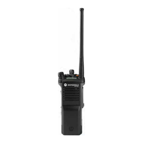
Radio Parts and Controls 16-Position Select Knob* Antenna Display On/Off/Volume Control Knob Bluetooth Pairing Indicator 3-Position A/B/C Switch* Top (Orange) Top Side (Select) Button* Microphone Button* 2-Position Concentric Switch* Accessory Push-to-Talk Connector Main (PTT) Button Speaker Belt Clip Side Button 1* Battery Side Button 2* Battery Latch... -
Page 29: Programmable Features
Call Response – Allows you to answer a private call. Programmable Features Dynamic Priority (Conventional Only) – Allows any channel Any reference in this manual to controls that are in a scan list (except for the Priority-One channel) to temporarily “preprogrammed”... -
Page 30: Assignable Settings Or Utility Functions
Repeater Access Button (RAB) (Conventional Only) – Enhanced Zone Bank – Provide access from up to 75 zones Allows to manually send a repeater access codeword. by toggling between 25 banks (A, B ... X or Y) of 3 zones. Reprogram Request (Trunking Only) –... -
Page 31: Push-To-Talk (Ptt) Button
Push-To-Talk (PTT) Button Identifying Status Indicators The PTT button on the side Your radio indicates its operational status through the following: of the radio serves two basic Status Icons ....... . . page 13 purposes : LED Indicator . - Page 32 Battery Power Level For IMPRES™ battery operation only – the icon • L = Radio is set at Low power. shown indicates the charge remaining in the • H = Radio is set at High power. battery. For all battery operation – the icon blinks when Scan the battery is low.
- Page 33 Basic Zone Bank 1 Secure Operation • • A = Radio is in Zone 1. On = Secure operation. • • B = Radio is in Zone 2. Off = Clear operation. • • C = Radio is in Zone 3. Blinking = Receiving an encrypted voice call.
-
Page 34: Led Indicator
Solid green – Radio is powering up, or is on a non-priority LED Indicator channel while in the Scan List Programming mode. The LED indicator shows the Blinking green – Radio is receiving an individual or telephone LED Indicator operational status of your radio. call, or is on a Priority-Two channel while in the Scan List Programming mode. -
Page 35: Intelligent Lighting Indicators
Intelligent Lighting Indicators This feature temporary changes the backlight of the top display screen to indicate a radio event has occurred. Note: This feature must be preprogrammed by a qualified radio technician. Backlight Notification When The radio initiates an emergency alarm or call. Orange Emergency Alerts The radio receives an emergency alarm or call. -
Page 36: Alert Tones
Alert Tones An alert tone is a sound or group of sounds. Your radio uses alert tones to inform you of your radio’s condition. The following table lists these tones and when they occur. You Hear Tone Name Heard Radio Self Test Fail When radio fails its power-up self test. - Page 37 You Hear Tone Name Heard Valid Key-Press When a valid key is pressed. Radio Self Test Pass When radio passes its power-up self test. Clear Voice At beginning of a non-coded communication. Short, Priority Channel Medium-Pitched When activity on a priority channel is received. Received Tone Emergency Alarm/Call...
- Page 38 You Hear Tone Name Heard Short, High-Pitched Low-Battery Chirp When battery is below preset threshold value. Tone (Chirp) Fast Ringing When system is searching for target of Private Call. Ringing Enhanced Call Sent When waiting for target of Private Call to answer the call. Phone Call Received When a land-to-mobile phone call is received.
- Page 39 You Hear Tone Name Heard Doh-Sol When EZB Up button is pressed to scroll the Enhance Zone Bank up. Enhanced Zone Bank Up Enhanced Zone Bank Sol-Doh When EZB Down button is pressed to scroll the Enhance Zone Bank down. Down English...
-
Page 40: General Radio Operation
Selecting a Zone General Radio Operation A zone is a group of channels. Once you understand how your APX 7000 Portable is configured, you are ready to use your radio. Use this navigation guide to familiarize yourself with the basic... -
Page 41: Selecting A Radio Channel
Selecting a Radio Channel Receiving and Responding to a Radio Call Once you have selected the required channel and/or zone, you A channel is a group of radio characteristics, such as transmit/ can proceed to receive and respond to calls. receive frequency pairs. -
Page 42: Receiving And Responding To A Talkgroup Call
Receiving and Responding to a Talkgroup Call Receiving and Responding to a Private Call (Trunking Only) To receive a call from a group of users, your radio must be configured as part of that talkgroup. A Private Call is a call from an individual radio to another individual radio. -
Page 43: Receiving And Responding To A Telephone Call (Trunking Only)
Procedure: Press the Call Response button within 20 seconds after the When you receive a Telephone Call: call indicators begin. Press and hold the PTT button to talk. Release the PTT You hear a telephone-type ringing and the LED blinks green. button to listen. -
Page 44: Making A Radio Call
Making a Radio Call Repeater or Direct Operation The REPEATER operation increases the radio’s range by You can select a zone, channel, or talkgroup by using: connecting with other radios through a repeater. The transmit • and receive frequencies are different. The preprogrammed Zone switch •... -
Page 45: Monitoring Features
Monitoring Features Conventional Mode Operation ® Your radio may be preprogrammed to receive Private-Line Radio users who switch from analog to digital radios often (PL) calls. assume that the lack of static on a digital channel is an indication that the radio is not working properly. This is not the Procedure: case. -
Page 46: Advanced Features
Advanced Call Features Advanced Features Use this navigation guide to learn more about advanced Receiving and Responding to a Selective Call features available with your radio: (Conventional Only) Advanced Call Features ..... . . page 28 This feature allows you to receive a call from or to call a specific Scan Lists . -
Page 47: Using The Dynamic Regrouping Feature (Trunking Only)
Using the Dynamic Regrouping Feature (Trunking Requesting a Reprogram (Trunking Only) Only) This feature allows you to notify the dispatcher when you want a This feature allows the dispatcher to temporarily reassign new dynamic regrouping assignment. selected radios to a particular channel where they can Procedure: communicate with each other. -
Page 48: Classifying Regrouped Radios
Scan Lists Classifying Regrouped Radios The dispatcher can classify regrouped radios into either of two Scan lists are created and assigned to individual channels/ categories: Select Enabled or Select Disabled. groups. Your radio scans for voice activity by cycling through the •... -
Page 49: Viewing And Changing The Priority Status
Scan Viewing and Changing the Priority Status Procedure: This feature allows you to monitor traffic on different channels Press the Top Side (Select) button to change the priority by scanning a preprogrammed list of channels. status of the currently displayed channel or the scan list status icon of the currently displayed channel. -
Page 50: Making A Dynamic Priority Change (Conventional Scan Only)
Note: Deleting a “nuisance” channel is only possible through Making a Dynamic Priority Change (Conventional the preprogrammed Nuisance Channel Delete Scan Only) button. While the radio is scanning, the dynamic priority change feature Procedure: allows you to temporarily assign any channel in a scan list (except for the Priority-One channel) as the Priority-Two When the radio is locked onto the channel to be deleted, channel. -
Page 51: Call Alert Paging
Call Alert Paging Emergency Operation This feature allows your radio to work like a pager. The Emergency feature is used to indicate a critical situation. If the Top (Orange) button is preprogrammed to send an Note: This feature must be preprogrammed by a qualified emergency signal, this signal overrides any other radio technician. -
Page 52: Sending An Emergency Alarm
Sending an Emergency Alarm Sending an Emergency Call (Trunking Only) This feature lets you send a data transmission, which identifies This feature gives your radio priority access on a channel. the radio sending the emergency, to the dispatcher. Note: The radio operates in the normal dispatch manner while in Emergency Call, except, if enabled, it returns Note: Emergency button press timer by default is set to 1... -
Page 53: Sending An Emergency Alarm With Emergency Call
Hold the radio vertically 1 to 2 inches (2.5 to 5.0 cm) from The radio enters the Emergency Call state when: your mouth. You receive the dispatcher’s acknowledgment. The display shows ACK RCVD. Press and hold the PTT button. Speak clearly into the microphone. -
Page 54: Sending A Silent Emergency Alarm
Sending a Silent Emergency Alarm Using the Emergency Keep-Alive Feature This feature allows you to send an Emergency Alarm to another This feature, when enabled, prevents the radio from being radio without any audio or visual indicators. turned off via the On/Off Control knob when the radio is in the Emergency state. -
Page 55: Fireground (Conventional Only)
The Fireground signals transmission is always exchanging data Fireground (Conventional Only) between your radio and the RF Modem and command terminal. The status of your radio includes The portable Fireground Communications System is designed for deployment at an incident scene. It consists of five central •... -
Page 56: Responding To Evacuation Indicator
Listen for a transmission. Adjust the Volume Control Knob if Responding to Evacuation Indicator necessary. When Incident Commander triggers Evacuation signal from his Press and hold the preprogrammed Volume Set button to command terminal, the RF Modem updates everyone in the hear the volume set tone. -
Page 57: Tactical Public Safety(Tps) (Conventional Only)
Tactical Public Safety(TPS) (Conventional Using TPS Emergency Transmission Only) Emergency Beacon – During Emergency if the TPS radio user pushes the Emergency button, the radio sounds a Beacon at the maximum volume of the radio at radio’s internal speaker Using TPS Normal Transmission and it is not adjustable. -
Page 58: Man Down
The Man Down feature has three phases: Man Down The radio senses the Man Down condition and Pre-Alert Man Down condition is determined based upon the radio tilt Timer is initiated. angle or a combination of radio tilt angle and the lack of radio Man Down condition continues for the time duration defined motion. -
Page 59: Pre-Alert Timer
Note: Emergency must be set up for this feature to operate. Post-Alert Timer For details on operating the Emergency alerts, please This timer sets the amount of time the radio needs to remain in see Emergency Operation on page 33. the Man Down condition before the Emergency alarm is transmitted. -
Page 60: Triggering Emergency
Procedure: Triggering Emergency Repositioning the radio or shaking the radio (when motion When the user does not clear the Man Down condition and the sensitivity is enabled). Post-Alert Timer comes to an end, Emergency Alarm or call is triggered. The radio sends emergency message to units within Press the preprogrammed Man Down Clear button to exit. -
Page 61: Testing The Man Down Feature
Testing the Man Down Feature Handling Man Down Functional Error Messages Procedure: Note: Enable the Emergency feature with Silent Alarm disabled, but not in Surveillance Mode before running If your radio display shows one of the following error this test on the radio. messages: HW BOARD ABSENT, MAN-DOWN HW ERROR or HW BOARD MISMATCH. -
Page 62: Secure Operations
Note: If the selected channel is preprogrammed for secure- Unlike other forms of security, Motorola digital encryption only operation – when you press the PTT button, an provides signaling that makes it virtually impossible for others to invalid mode tone sounds and the display shows SEC decode any part of an encrypted message. -
Page 63: Managing Encryption
Managing Encryption Using the Multikey Feature This feature allows the radio to be equipped with different Loading an Encryption Key encryption keys and supports the DES-OFB algorithm. Note: Refer to the key-variable loader (KVL) manual for There are two types: equipment connections and setup. -
Page 64: Erasing The Selected Encryption Keys
Erasing the Selected Encryption Keys Requesting an Over-the-Air Rekey (ASTRO Only) This feature allows you to erase all or selected encryption keys. This feature, also known as OTAR, allows the dispatcher to reprogram the encryption keys in the radio remotely. The Procedure: dispatcher performs the rekey operation upon receiving a rekey request from the user. -
Page 65: Mdc Over-The-Air Rekeying (Otar) Page
MDC Over-the-Air Rekeying (OTAR) Page Hear Clear This feature allows to view or define MDC Over-the-Air There are two components of Hear Clear. Rekeying (OTAR) features.It is applied only when operating in Companding: secure encrypted mode and only for conventional Reduces the channel noise, e.g. -
Page 66: Trunking System Controls
Trunking System Controls Going Out of Range When your radio goes out of the range of the system, it can no longer lock onto a control channel. Using the Failsoft System Procedure: The failsoft system ensures continuous radio communications during a trunked system failure. If a trunking system fails A low-pitched tone sounds. -
Page 67: Using The Site Trunking Feature
Using the Site Trunking Feature Viewing and Changing a Site If the zone controller loses communication with any site, that This feature allows you to view the name of the current site or site reverts to site trunking. forces your radio to change to a new one. The display shows the currently selected zone/channel Viewing the Current Site combination and STE TRNK. -
Page 68: Mission Critical Wireless - Bluetooth
- Bluetooth Procedure: Press the preprogrammed button to turn the Bluetooth off. This feature allows your radio to extend its functionality by connecting to external proprietary Motorola Accessories. A short, medium-pitched tone sounds. The display shows momentary BT OFF, and disappears. -
Page 69: Bluetooth Drop Timer
Bluetooth Drop Timer Re-Pair Timer The Bluetooth Drop Timer has two different settings and Re-Pair Timer Scenarios Options functions, depending upon the selection of the Re-Pair Timer. • When the radio is powered OFF, pairing Re-Pair Timer Drop Timer Options key is lost immediately, and accessory Options attempts to pair again. -
Page 70: Pairing The Bluetooth Device With The Radio
Procedure: Pairing the Bluetooth Device with the Radio Note: Bluetooth tones, Bluetooth menu and Preprogrammed buttons must be preprogrammed by a qualified radio technician. Check with your dealer or system administrator for more information. Bluetooth Pairing With your radio’s Bluetooth feature ON, and the Bluetooth tones Location enabled: Turn on the accessory, then place it close to your radio... -
Page 71: Indicating The Bluetooth Connection Is Lost
Turning the Bluetooth Audio On (Routing the If the connecting process is immediately following the Audio from the Radio to the Headset) pairing process and the connecting process fails to Procedure: complete within the 6 seconds, the radio sounds a decremental-pitched tone to indicate unpaired. -
Page 72: Clearing All Bluetooth Devices Information
The radio display shows VOL XX and sounds a short, Place it close to the radio aligning the Bluetooth Pairing medium-pitched tone. Location on LEX 700 with the Bluetooth Pairing Location on the radio. Clearing All Bluetooth Devices Information If the pairing process is successful, you hear an incremental-pitched tone from the radio. -
Page 73: Programming Over Project 25 (Pop 25) (Astro 25 And Astro Conventional)
Programming Over Project 25 (POP 25) The radio continues to connect to LEX 700. If the connecting process is successful, you hear an (ASTRO 25 and ASTRO Conventional) incremental-pitched tone. The display shows LEX 700 CONNCTED, and the Bluetooth icon turns from This feature enables configuration data to be upgraded to your radio over-the-air. -
Page 74: Utilities
Procedure: Utilities Use the preprogrammed Basic Zone Bank button to toggle the position between Bank 1 and Bank 2. Using the Flip Display The top display shows the status icons (A, B, C, D, E or F) or This feature allows you to reverse the content of the top display the zone name based on the bank and switch position upside down. -
Page 75: Selecting The Power Level
Procedure: Settings: Select Low for a shorter transmitting distance and to • Press the preprogrammed EZB Up or EZB Down button to conserve power. scroll the EZB up or down. Select High for a longer transmitting distance. • Press and hold the preprogrammed EZB Up or EZB Down Procedure: button to fast scroll the EZB up or down. -
Page 76: Locking And Unlocking The Controls
Locking and Unlocking the Controls Turning Voice Mute On or Off You can lock your radio’s programmable buttons, switches and You can enable and disable voice transmission, if needed. rotary knobs to avoid inadvertent entry. Check with your dealer Procedure: or qualified technician for best selection to suite your usage. -
Page 77: Using The Conventional Squelch Operation Features
The timer is defaulted at 60 seconds, but it can be Using the Conventional Squelch Operation preprogrammed from 3 to 120 seconds, in 15-second intervals, Features or it can be disabled entirely for each radio mode, by a qualified This feature filters out unwanted calls with low signal strength or radio technician. -
Page 78: Digital Options
Digital Options Using the PL Defeat Feature One or more of the following options may be preprogrammed in This feature allows you to override any coded squelch (DPL or your radio. Check with your dealer or system administrator for PL) that might be preprogrammed to a channel. The radio will also unmute to any digital activity on a digital channel. -
Page 79: Using The Digital Ptt Id Feature
Three variations of smart PTT are available: Using the Digital PTT ID Feature Transmit Inhibit This feature allows you to see the radio ID (number) of the radio You cannot transmit if any traffic is on Busy Channel from whom you are currently receiving a transmission. This ID, detected on the channel. -
Page 80: Voice Announcement
• The radio powers up. The radio announces the current zone Voice Announcement and channel it is transmitting. This feature enables the radio to audibly indicate the current • Press the preprogrammed voice announcement button feature mode, Zone or Channel the user has just assigned. This (which specifically programmed to playback the current zone audio indicator can be customized per customer requirements. -
Page 81: Helpful Tips
• (For APX 7000 R Radios Only) Your radio is designed to be submerged to a maximum depth of 6 feet, with a maximum submersion time of 2 hours. Exceeding either maximum limit may result in damage to the radio. -
Page 82: Cleaning Your Radio
Cleaning Your Radio • (For APX 7000 R Radios Only) Elastomer technology materials used for seals Procedure: in rugged portable radios can age with time and a u t i o n environmental exposure. Therefore, Motorola To clean the external surfaces of your radio:... -
Page 83: Handling Your Radio
• Avoid subjecting the radio to an excess of liquids. Do not communication equipment in perfect operating condition. A submerge the radio unless it is a ruggedized, APX 7000 R nationwide service organization is provided by Motorola to model. support maintenance services. Through its maintenance and •... -
Page 84: Taking Care Of The Battery
Taking Care of the Battery Gauge Battery Charge 76% to 100% full* Checking the Battery Charge Status Your radio can indicate the battery’s charge status through: • the LED and sounds. 51% to 75%* • the fuel gauge icon on the display. LED and Sounds 26% to 50%* When your battery is low:... -
Page 85: Battery Recycling And Disposal
Battery Recycling and Disposal In the U.S. and Canada, Motorola participates in the nationwide Rechargeable Battery Recycling Corporation (RBRC) program for battery collection and recycling. Many retailers and dealers participate in this program. For the location of the drop-off facility closest to you, access RBRC's Internet web site at www.rbrc.com... -
Page 86: Accessories
Highlights for the Accessories Accessories GPS only antenna is only used in either a single band UHF The accessory link below is for APX radios. Not all accessories or 700/800 application where the Public Safety Microphone are FCC certified for operation with all APX models and/or (PSM) is used with the corresponding PSM antenna. -
Page 87: Appendix: Maritime Radio Use In The Vhf Frequency Range
State the position of the vessel in distress, using any Appendix: Maritime Radio Use in the information that will help responders to locate you, e.g.: VHF Frequency Range • latitude and longitude • bearing (state whether you are using true or magnetic Take a moment to review the following: north) Special Channel Assignments . -
Page 88: Operating Frequency Requirements
Table A-1: VHF Marine Channel List (Continued) Operating Frequency Requirements Frequency (MHz) Channel A radio designated for shipboard use must comply with Federal Number Transmit Receive Communications Commission Rule Part 80 as follows: 156.150 160.750 • on ships subject to Part II of Title III of the Communications Act, the radio must be capable of operating on the 156.800 156.200 160.800... - Page 89 Table A-1: VHF Marine Channel List (Continued) Table A-1: VHF Marine Channel List (Continued) Frequency (MHz) Frequency (MHz) Channel Channel Number Number Transmit Receive Transmit Receive 157.150 161.750 157.200 161.800 157.250 161.850 77** 156.875 – 157.300 161.900 156.925 161.525 157.350 161.950 156.975 161.575...
- Page 90 Automatic Registration Service signal is being received so that the user does not have to listen to “noise”. Motorola standard for wireless digital ASTRO 25 trunked communications. A software-controlled, computer-driven device that receives and generates data for...
- Page 91 Term Definition Term Definition In a trunking system, one of the channels A feature that allows the dispatcher to that is used to provide a continuous, two- Dynamic temporarily reassign selected radios to a Control Channel way/data communications path between Regrouping single special channel so they can the central controller and all radios on the...
- Page 92 Term Definition Term Definition A life-saving feature that senses the radio The user talks on a preprogrammed Non-Tactical/ user may be in trouble by monitoring the emergency channel. The emergency alarm Revert whether the radio is in a vertical or is sent out on this same channel.
- Page 93 Term Definition Term Definition A conventional radio feature, where you The user talks on the channel that was Tactical/ talk through a receive/transmit facility that selected before the radio entered the Non-Revert Repeater re-transmits received signals, in order to emergency state. improve communications range and Bypass a repeater and talk directly to coverage.
-
Page 94: Commercial Warranty
Product manufactured by MOTOROLA. MOTOROLA assumes no Commercial Warranty obligations or liability for additions or modifications to this warranty unless made in writing and signed by an officer of MOTOROLA. Limited Warranty Unless made in a separate agreement between MOTOROLA and the original end user purchaser, MOTOROLA does not warrant the installation, maintenance or service of the Product. - Page 95 Product for which it and insurance prepaid, to an authorized warranty service location. is specified. Warranty service will be provided by MOTOROLA through one of its H)Freight costs to the repair depot. authorized warranty service locations. If you first contact the I) A Product which, due to illegal or unauthorized alteration of the company which sold you the Product (e.g., dealer or...
- Page 96 VI. PATENT AND SOFTWARE PROVISIONS: MOTOROLA will have no liability with respect to any claim of patent infringement which is based upon the combination of the Product or MOTOROLA will defend, at its own expense, any suit brought parts furnished hereunder with software, apparatus or devices not...
- Page 97 Motorola Solutions Australia’s limited warranty below is in addition to any rights and remedies you may have under the Australian Consumer Law. If you have any queries, please call Motorola Solutions Australia at 1800 457 439. You may also visit our website: http://www.motorola.com/Business/XA-EN/...
- Page 98 Notes English...
- Page 100 Schaumburg, Illinois 60196 U.S.A. MOTOROLA, MOTO, MOTOROLA SOLUTIONS and the Stylized M logo are trademarks or registered trademarks of Motorola Trademark Holdings, LLC and are used under license. All other trademarks are the property of their respective owners. © 2009–2012 Motorola Solutions, Inc. All rights reserved.