Motorola APX7000 User Manual
Hide thumbs
Also See for APX7000:
- Detailed service manual (644 pages) ,
- Basic service manual (292 pages) ,
- User manual (213 pages)

Related Manuals for Motorola APX7000


Summary of Contents for Motorola APX7000
- Page 2 ______________ Zones and Channels • Zone – Zone switch to desired zone. *68007024033* • Channel – Channel switch to desired channel. 68007024033-A © 2009 by Motorola, Inc. All Rights Reserved. 03/09 1301 E. Algonquin Rd., Schaumburg, IL 60196-1078, U.S.A. English...
- Page 3 Sending an Emergency Call Display Status Icons On = Secure operation. Off = Clear operation. Press the Emergency button. Blinking = Receiving an encrypted Blinks when the battery is low. voice call. Press and hold the PTT button. Speak clearly The more stripes, the stronger the into the microphone.
-
Page 4: Declaration Of Conformity
This declaration is applicable to your radio only if your radio is labeled with the FCC logo shown below. DECLARATION OF CONFORMITY Per FCC CFR 47 Part 2 Section 2.1077(a) Responsible Party Name: Motorola, Inc. Address: 1301 East Algonquin Road, Schaumburg, IL 60196-1078, U.S.A. Phone Number: 1-800-927-2744 Hereby declares that the product:... - Page 5 Note: This equipment has been tested and found to comply with the limits for a Class B digital device, pursuant to part 15 of the FCC Rules. These limits are designed to provide reasonable protection against harmful interference in a residential installation.
-
Page 6: Table Of Contents
Preparing Your Radio for Use ....2 Contents Charging the Battery ......3 Battery Charger . - Page 7 Intelligent Lighting Indicators ....13 Advanced Features ..... 23 Alert Tones .
- Page 8 Emergency Operation ..... . . 28 Locking and Unlocking a Site ....36 Sending an Emergency Alarm .
- Page 9 Cleaning Your Radio ..... . . 43 Appendix: Maritime Radio Use in the Handling Your Radio ..... . . 43 VHF Frequency Range .
-
Page 10: Important Safety Information
Product Safety and RF Exposure booklet enclosed with your radio (Motorola Publication part number 6881095C98) to ensure compliance with RF energy exposure limits. For a list of Motorola-approved antennas, batteries, and other accessories, visit the following website: http://www.motorola.com/governmentandenterprise English... -
Page 11: Computer Software Copyrights
Laws in the written permission of Motorola. No part of this manual United States and other countries preserve for Motorola may be reproduced, distributed, or transmitted in any... -
Page 12: Getting Started
Notations Used in This Manual Getting Started Throughout the text in this publication, you will notice the use of Take a moment to review the following: WARNING, Caution, and Note. These notations are used to How to Use This Guide ......page 1 emphasize that safety hazards exist, and the care that must be Notations Used in This Manual . -
Page 13: What Your Dealer/System Administrator Can Tell You
What Your Dealer/System Administrator Preparing Your Radio for Use Can Tell You Assemble your radio by following these steps: Check with your dealer or system administrator, if the radio is to Charging the Battery ......page 3 be operated in extremely cold temperatures (less than -20°C), Battery Charger . -
Page 14: Charging The Battery
Prior to using a new battery, charge it for a minimum of 16 hours to ensure optimum capacity and performance. For a list of Motorola-authorized batteries available for use with your radio, see Batteries and Battery Accessories on page 46. -
Page 15: Attaching The Antenna
Attaching the Antenna To remove the battery, turn the radio off. Squeeze With the radio turned off, set the antenna in its receptacle and the release latches on the turn clockwise to attach it to the radio. bottom of the battery until the battery releases from the radio. -
Page 16: Attaching The Accessory Connector Cover
Attaching the Accessory Connector Attaching the Belt Clip Cover The accessory connector is located on the antenna side of the Align the grooves of the radio. It is used to connect accessories to the radio. belt clip with those of the radio and press upward Note: To prevent damage to the connector, shield it with the... -
Page 17: Turning On The Radio
Turning On the Radio Rotate the On/Off/Volume Control Knob clockwise until you hear a click. To turn off the radio, rotate the On/Off/Volume Control Knob counterclockwise until you hear a click. If the power-up test is successful, you see SELFTEST on the radio’s display momentarily, followed by the Home screen. -
Page 18: Adjusting The Volume
Adjusting the Volume Identifying Radio Controls To increase the volume, turn the On/Off/Volume Control Knob Take a moment to review the following: clockwise. Radio Parts and Controls ......page 8 Programmable Features . -
Page 19: Radio Parts And Controls
Radio Parts and Controls 16-Position Select Knob* Antenna On/Off/Volume Control Knob 3-Position A/B/C Display Switch* Top (Orange) Top Side (Select) Button* Microphone Button* 2-Position Concentric Switch* Accessory Push-to-Talk Connector Main (PTT) Button Speaker Belt Clip Side Button 1* Battery Side Button 2* Battery Latch * These radio controls/buttons are programmable. -
Page 20: Programmable Features
Monitor – Monitors a selected channel for all radio traffic until Programmable Features function is disabled. Any references in this manual to controls that are Nuisance Delete – Temporarily removes an unwanted channel, “preprogrammed” mean that a qualified radio technician must except for priority channels or the designated transmit channel, use the radio’s programming software to assign a feature to a from the scan list. -
Page 21: Assignable Settings Or Utility Functions
Zone Select – Allows selection from a list of zones. Push-To-Talk (PTT) Button Zone Bank – Allows selection from a larger list of zones. The PTT button on the side of the radio serves two basic Assignable Settings or Utility Functions purposes: Flip –... -
Page 22: Identifying Status Indicators
Direct Identifying Status Indicators • On = Radio is currently configured for direct Your radio indicates its operational status through the following: radio to radio communication (during conventional operation only). Status Icons ....... . . page 11 •... -
Page 23: Led Indicator
LED Indicator Vote Scan Enabled The vote scan feature is enabled. The LED indicator shows the LED Indicator operational status of your radio. View/Program Mode Top Display Radio is in the view or program mode. Solid red – Radio is transmitting. -
Page 24: Intelligent Lighting Indicators
Intelligent Lighting Indicators This feature temporary changes the backlight of the top display screen to help signal that a radio event has occurred. Note: This feature must be preprogrammed by a qualified radio technician. Backlight Notification When The radio initiates an emergency alarm or call. Orange Emergency Alerts The radio receives an emergency alarm or call. -
Page 25: Alert Tones
Alert Tones An alert tone is a sound or group of sounds. Your radio uses alert tones to inform you of your radio’s conditions. The following table lists these tones and when they occur. You Hear Tone Name Heard Radio Self Test Fail When radio fails its power-up self test. - Page 26 You Hear Tone Name Heard Valid Key-Press When correct key is pressed. Radio Self Test Pass When radio passes its power-up self test. Clear Voice At beginning of a non-coded communication. Short, Medium-Pitched Priority Channel When activity on a priority channel is received. Tone Received Emergency Alarm Entry...
- Page 27 You Hear Tone Name Heard Short, High-Pitched Low-Battery Chirp When battery is below preset threshold value. Tone (Chirp) Fast Ringing When system is searching for target of Private Call. Ringing Enhanced Call Sent When waiting for target of Private Call to answer the call. Phone Call Received When a land-to-mobile phone call is received.
-
Page 28: General Radio Operation
Selecting a Zone General Radio Operation A zone is a group of channels. Once you understand how your APX 7000 Portable is configured, you are ready to use your radio. Use this navigation guide to familiarize yourself with the basic Call features: 3-Position Selecting a Zone . -
Page 29: Selecting A Radio Channel
Selecting a Radio Channel Receiving and Responding to a Radio Call Once you have selected the required channel and/or zone, you A channel is a group of radio characteristics, such as transmit/ can proceed to receive and respond to calls. receive frequency pairs. -
Page 30: Receiving And Responding To A Talkgroup Call
Receiving and Responding to a Talkgroup Call Receiving and Responding to a Private Call (Trunking Only) To receive a call from a group of users, your radio must be configured as part of that talkgroup. A Private Call is a call from an individual radio to another individual radio. -
Page 31: Receiving And Responding To A Telephone Call (Trunking Only)
Procedure: Press the Call Response button within 20 seconds after the When you receive a Telephone Call: call indicators begin. Press and hold the PTT button to talk. Release the PTT You hear a telephone-type ringing and the LED blinks green. button to listen. -
Page 32: Making A Radio Call
Making a Radio Call Repeater or Direct Operation The REPEATER operation increases the radio’s range by You can select a zone, channel, or talkgroup by using: connecting with other radios through a repeater. The transmit • and receive frequencies are different. The preprogrammed Zone switch •... -
Page 33: Monitoring Features
Monitoring Features Conventional Mode Operation ® Your radio may be preprogrammed to receive Private-Line Radio users who switch from analog to digital radios often (PL) calls. assume that the lack of static on a digital channel is an indication that the radio is not working properly. This is not the Procedure: case. -
Page 34: Advanced Features
Advanced Call Features Advanced Features Use this navigation guide to learn more about advanced Receiving and Responding to a Selective Call features available with your radio: (ASTRO Conventional Only) Advanced Call Features ..... . . page 23 This feature allows you to receive a call from or to call a specific Scan Lists . -
Page 35: Using The Dynamic Regrouping Feature (Trunking Only)
Using the Dynamic Regrouping Feature (Trunking Requesting a Reprogram (Trunking Only) Only) This feature lets you notify the dispatcher that you want a new This feature allows the dispatcher to temporarily reassign dynamic regrouping assignment. selected radios to a single special channel so they can Procedure: communicate with each other. -
Page 36: Classifying Regrouped Radios
Scan Lists Classifying Regrouped Radios The dispatcher can classify regrouped radios into either of two Scan lists are created and assigned to individual channels/ categories: Select Enabled or Select Disabled. groups. Your radio scans for voice activity by cycling through the •... -
Page 37: Scan
Scan A Scan icon indicates that the current channel is in the scan list as a non-priority channel. The LED lights up solid green. This feature allows you to monitor traffic on different channels A Priority-Two Channel Scan icon indicates that the current by scanning a preprogrammed list of channels. -
Page 38: Making A Dynamic Priority Change (Conventional Scan Only)
Note: Deleting a “nuisance” channel is only possible through Making a Dynamic Priority Change (Conventional the preprogrammed Nuisance Channel Delete Scan Only) button. While the radio is scanning, the dynamic priority change feature Procedure: allows you to temporarily assign any channel in a scan list (except for the Priority-One channel) as the Priority-Two When the radio is locked onto the channel to be deleted, channel. -
Page 39: Call Alert Paging
Call Alert Paging Emergency Operation This feature allows your radio to work like a pager. The Emergency feature is used to indicate a critical situation. If the Top (Orange) button is preprogrammed to send an Note: This feature must be preprogrammed by a qualified emergency signal, this signal overrides any other radio technician. -
Page 40: Sending An Emergency Alarm
Sending an Emergency Alarm Sending an Emergency Call (Trunking Only) This feature allows you to send a data transmission, which This feature gives your radio priority access on a channel. identifies the radio sending the emergency, to the dispatcher. Note: The radio operates in the normal dispatch manner Procedure: while in Emergency Call, except, if enabled, it returns... -
Page 41: Sending An Emergency Alarm With Emergency Call
Hold the radio vertically 1 to 2 inches (2.5 to 5.0 cm) from The radio enters the Emergency Call state when: your mouth. You receive the dispatcher’s acknowledgment. The display shows ACK RCVD. Press and hold the PTT button. Speak clearly into the microphone. -
Page 42: Sending A Silent Emergency Alarm
Sending a Silent Emergency Alarm Using the Emergency Keep-Alive Feature This feature allows you to send an Emergency Alarm to another This feature, when enabled, prevents the radio from being radio without any audio or visual indicators. turned off via the On/Off Control knob when the radio is in the Emergency state. -
Page 43: Secure Operations
Note: If the selected channel is preprogrammed for secure- Unlike other forms of security, Motorola digital encryption only operation – when you press the PTT button, an provides signaling that makes it virtually impossible for others to invalid mode tone sounds and the display shows SEC decode any part of an encrypted message. -
Page 44: Managing Encryption
Managing Encryption Using the Multikey Feature This feature allows the radio to be equipped with as many as 48 Loading an Encryption Key different encryption keys and supports the DES-OFB algorithm. Note: Refer to the key-variable loader (KVL) manual for There are two types: equipment connections and setup. -
Page 45: Using The Key Zeroization Feature
Using the Key Zeroization Feature Requesting an Over-the-Air Rekey (ASTRO Conventional Only) This feature allows you to erase all or selected encryption keys. This feature, also known as OTAR, allows the dispatcher to Procedure: reprogram the encryption keys in the radio remotely. The dispatcher performs the rekey operation upon receiving a rekey Use the preprogrammed Top Side (Select) button and Top request from the user. -
Page 46: Trunking System Controls
Trunking System Controls Going Out of Range When your radio goes out of the range of the system, it can no longer lock onto a control channel. Using the Failsoft System Procedure: The failsoft system ensures continuous radio communications during a trunked system failure. If a trunking system fails A low-pitched tone sounds. -
Page 47: Using The Site Trunking Feature
Using the Site Trunking Feature Viewing and Changing a Site If the zone controller loses communication with any site, that This feature allows you to view the number of the current site or site reverts to site trunking. force your radio to change to a new one. The display shows the currently selected zone/channel Viewing the Current Site combination and STE TRNK. -
Page 48: Utilities
Procedure: Utilities Use the preprogrammed Zone Bank button to toggle the position between Bank 1 and Bank 2. Using the Flip Display The top display shows the status icons (A, B, C, D, E or F) or This feature allows you to flip the content of the top display the zone name based on the bank and switch position upside down. -
Page 49: Controlling The Display Backlight
Procedure: Turning Voice Mute On or Off Press the preprogrammed Transmit Power Level Switch You can enable and disable voice transmission, if needed. to toggle the power level between low and high power. Procedure: The display shows LOW PWR and the low power icon. Press the preprogrammed Voice Mute button to turn the feature off or on. -
Page 50: Using The Conventional Squelch Operation Features
The timer is defaulted at 60 seconds, but it can be Using the Conventional Squelch Operation preprogrammed from 3 to 120 seconds, in 15-second intervals, Features or it can be disabled entirely for each radio mode, by a qualified This feature filters out unwanted calls with low signal strength or radio technician. -
Page 51: Digital Options
Digital Options Using the PL Defeat Feature One or more of the following options may be preprogrammed in This feature allows you to override any coded squelch (DPL or your radio. Check with your dealer or system administrator for PL) that might be preprogrammed to a channel. The radio will also unmute to any digital activity on a digital channel. -
Page 52: Using The Digital Ptt Id Feature
If you try to transmit on an active smart-PTT channel, you hear Using the Digital PTT ID Feature an alert tone, and the transmission is inhibited. The LED lights This feature allows you to see the radio ID (number) of the radio up solid yellow to indicate that the channel is busy. -
Page 53: Helpful Tips
Caring for Your Radio Helpful Tips • Take a moment to review the following: The APX 7000 radio casting has a vent Caring for Your Radio ......page 42 port that allows for Cleaning Your Radio . -
Page 54: Cleaning Your Radio
Apply the solution sparingly with a stiff, non-metallic, short- assure the watertight integrity of the radio. Motorola details the disassembly, test, and bristled brush, making sure excess detergent does not get reassembly procedures along with necessary entrapped near the connectors, controls or crevices. -
Page 55: Servicing Your Radio
• the fuel gauge icon on the display. Proper repair and maintenance procedures will assure efficient operation and long life for this product. A Motorola maintenance LED and Sounds agreement will provide expert service to keep this and all other When your battery is low: communication equipment in perfect operating condition. -
Page 56: Battery Recycling And Disposal
Battery Recycling and Disposal Gauge Battery Charge In the U.S. and Canada, Motorola participates in the nationwide Rechargeable Battery Recycling Corporation (RBRC) program 76% to 100% full for NiCd battery collection and recycling. Many retailers and dealers participate in this program. -
Page 57: Accessories
• 2100 mAh, IMPRES NiMH (Std), IP57 (NNTN7037_) Accessories • 2500 mAh, IMPRES Li-Ion, IP57 (NNTN7038_) Your radio is compatible with the approved accessories listed in • 2100 mAh, IMPRES NiMH (Std), IP57 Rugged this chapter. Contact your dealer for details. (NNTN7573_) Antennas . -
Page 58: Chargers
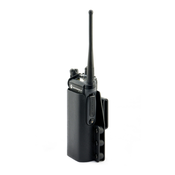
• • Hard Leather Carry Case (High Activity) with 2.75” Swivel IMPRES Multi-Unit, Display (US Plug) (NNTN7073_) Belt Loop, D-Rings, and T-Strap, for Short Radio • IMPRES Multi-Unit, Display (UK Plug) (NNTN7074_) (PMLN5324_) • • IMPRES Multi-Unit, Display (Argentina Plug) Nylon Carry Case with 3”... -
Page 59: Audio Accessories
• Audio Accessories 1-Wire, Receive Only Earpiece, Beige (RLN5879_) • 2-Wire, One Programmable Button, Black (RLN5880_) • Small Remote Speaker Microphone, IP54, 3.5 mm Jack, • 2-Wire, One Programmable Button, Beige (RLN5881_) Receive Only (PMMN4024_) • 2-Wire with Translucent Tube, One Programmable Button, •... -
Page 60: Appendix: Maritime Radio Use In The Vhf Frequency Range
State the position of the vessel in distress, using any Appendix: Maritime Radio Use in the information that will help responders to locate you, e.g.: VHF Frequency Range • latitude and longitude • bearing (state whether you are using true or magnetic Take a moment to review the following: north) Special Channel Assignments . -
Page 61: Operating Frequency Requirements
Table A-1: VHF Marine Channel List (Continued) Operating Frequency Requirements Frequency (MHz) Channel A radio designated for shipboard use must comply with Federal Number Transmit Receive Communications Commission Rule Part 80 as follows: 156.150 160.750 • on ships subject to Part II of Title III of the Communications Act, the radio must be capable of operating on the 156.800 156.200 160.800... - Page 62 Table A-1: VHF Marine Channel List (Continued) Table A-1: VHF Marine Channel List (Continued) Frequency (MHz) Frequency (MHz) Channel Channel Number Number Transmit Receive Transmit Receive 157.150 161.750 157.200 161.800 157.250 161.850 77** 156.875 – 157.300 161.900 156.925 161.525 157.350 161.950 156.975 161.575...