Table of Contents
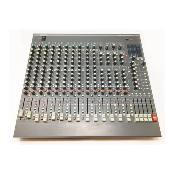
AUDIO MIXER
SRP-V110
Operating instructions
Before operating the unit, please read this manual and the supplied
"WARNING" thoroughly and retain it for future reference.
Precautions
On safety (Refer to the supplied "WARNING".)
• Should any liquid or solid object fall into the cabinet, unplug the unit and
have it checked by qualified personnel before operating it any further.
• Unplug the unit from the wall outlet if it is not to be used for an extended
period of time. To disconnect the cord, pull it out by grasping the plug.
Never pull the cord itself.
On installation
• Do not install the unit in a location near heat sources such as radiators or
air ducts, or in a place subject to direct sunlight, excessive dust,
mechanical vibration or shock.
On operation
• Before making program source connections, be sure to turn the power
switch off and unplug the unit.
• When the unit is not used, turn the power off to conserve energy and to
extend the useful life of your unit.
On cleaning the cabinet
Clean the cabinet, panel and controls with a soft cloth lightly moistened
with mild detergent solution. Do not use any type of abrasive pad, scouring
powder or solvent such as alcohol or benzine.
On repacking
Do not throw away the carton and the packing material. It makes an ideal
container for transporting the unit.
When shipping the unit for repair work or to another location, repack it as it
was.
If you have any questions or problems concerning your unit, please contact
your nearest Sony dealer.
To prevent fire or shock hazard, do not
expose the unit to rain or moisture.
To avoid electrical shock, do not open
the cabinet. Refer servicing to qualified
personnel only.
© 1998 by Sony Sound Tec Corporation
Table of Contents
Main characteristics ...............................
Dimensions ..............................................
Connections example ............................
Name and function of each part ...........
...................................
.....................................
.................................
Block diagram .........................................
Main specifications ................................
Trouble-shooting guide .........................
This symbol is intended to alert the user to the
presence of uninsulated "dangerous voltage"
within the product's enclosure that may be of
sufficient magnitude to constitute a risk of
electric shock to persons.
This symbol is intended to alert the user to the
presence of important operating and
maintenance (servicing) instructions in the
literature accompanying the appliance.
*The caution marking is put on the bottom enclosure.
2-346-297-21 (1)
..............................
.............................
2
2
3
4
4
6
8
9
!º
!™
!£
!¢
Table of Contents

Related Manuals for Sony SRP-V110


Summary of Contents for Sony SRP-V110
-
Page 1: Table Of Contents
This symbol is intended to alert the user to the presence of important operating and maintenance (servicing) instructions in the literature accompanying the appliance. *The caution marking is put on the bottom enclosure. © 1998 by Sony Sound Tec Corporation... -
Page 2: Main Characteristics
Main characteristics Equipped with 8 AUX channels This is a small, multi-functional eight-group buses audio mixer combined with a small/mid-sized SR system and AUX 1/2 can be used as STEREO AUX of the pre-fader. multi track recorder, etc. that supports recording systems. AUX 3/4 can (simultaneously) switch between the pre and post faders. -
Page 3: Connections Example
Connections example SR system connection Keyboard Compressor AUDIO MIXER SRP-V110 Microphone CD or MD Player Compressor Graphic Equalizer Graphic Equalizer Effector Power Amplifier Power Amplifier Main Speaker Monitor Speaker Recording system connection Keyboard Compressor Multi Track Recorder Microphone CD or MD Player... -
Page 4: Name And Function Of Each Part
Name and function of each part MONO INPUT section 1 POWER switch When the switch is pressed to the ON side, the power is turned on. 2 LEVEL control This controls the input signals from the MIC or LINE connectors at a suitable level. When connected to the MIC connector, the input signal level can be controlled between –10 - –60 dBu, and when connected to the LINE connector, it can be controlled between +10 -... -
Page 5: Pan Control
9 AUX 1-2 PAN control !§ PAN control When turned towards the “1”, sound is shifted to the When turned in the “L ODD” direction, sound is AUX 1 bus, and when turned in the “2” direction, it is shifted to the MASTER L, GROUP 1, 3, 5 and 7 (odd shifted to the AUX 2 bus. -
Page 6: Stereo Input Section
Name and function of each part STEREO INPUT section !∞ -∞ -∞ -∞ -∞ -10dBs -10dBs -10dBs -10dBs HIGH HIGH HIGH HIGH -∞ -∞ -∞ -∞ -∞ -∞ -∞ -∞ - ∞ -∞ -∞ -∞ -∞ -∞ -∞ -∞ -∞ -∞... -
Page 7: Balance Control
9 ON button ST1 - ST4 channels When turned on, the signals from the channels are routed to each output. However, the PFL function is available even if this switch is turned off. 1 –10 dBs button When this button is turned off, the reference input !º... -
Page 8: Monitor Section
MONITOR OUTPUT connectors, and signals from channels whose PFL or AFL buttons are turned on can be confirmed. 2 PEAK meter indicator AUDIO MIXER SRP-V110 This is lit up when the level meter is used as a peak meter. PHONES... -
Page 9: Master Section
It is switched to pre-fader when it is on, and post fader when it is off. 3 AFL buttons AUDIO MIXER SRP-V110 The signals after the AUX MASTER volume are routed to the PHONES or MONITOR OUT connectors, and PHONES displays the level on the meter. -
Page 10: Back Panel Section
Name and function of each part Back panel section GRP/ TAPE STEREO INPUT MONO INPUT DIRECT L(MONO) L(MONO) L(MONO) INSERT LINE !£ +48V MONITOR L(MONO) !º L(MONO) L(MONO) INSERT LINE INSERT OUTPUT MASTER AUX OUTPUT !™ !¡ 1 MONO INPUT MIC connectors 5 STEREO INPUT connectors XLR-3-31 type Phone jacks (ST1 –... - Page 11 GRP/ TAPE MONO INPUT MONO INPUT DIRECT INSERT LINE INSERT LINE INSERT LINE INSERT LINE INSERT LINE INSERT LINE INSERT LINE INSERT LINE 8 AUX OUTPUT connectors !£ +48 V button Phone jacks (Unbalanced, reference level: +4 dBu) This is the button to supply power (DC +48 V) for condenser microphones to the MIC connectors of the 9 2TR OUT connectors MONO INPUT channels 1 - 8.
- Page 12 Block diagram +48V FADER PEAK STEREO L TAPE FADER OUTPUT +4dBs -10 - -60dBs INSERT LINE -20dB FREQ +10 - -40dBs LEVEL LEVEL STEREO R LOW MID HIGH INSERT OUTPUT +4dBs MONI INSERT TAPE INPUT AUX1-2 -10dBs AUX3 OUTPUT GROUP/DIRECT AUX4 OUTPUT DIRECT...
-
Page 13: Main Specifications
Main specifications Name Connector type Circuit Reference level Maximum level Impedance Suitable load impedance MONO INPUT XLR-3-31 type Balanced –60 - –10 dBu –37 - +13 dBu 2.2 kΩ — LINE ø 6.3 Phone –40 - +10 dBu –17 - +27 dBu 22 kΩ... - Page 14 Trouble-shooting guide In the event of any unexpected problems, please double-check the following points. If after that, normal operation cannot be resumed, contact the store from which the item was purchased, or your nearest Sony dealer. Condition Causes/Solutions When the POWER switch is turned on, the power •...
- Page 16 Printed in Japan...