Quick Links
See also:
Manual
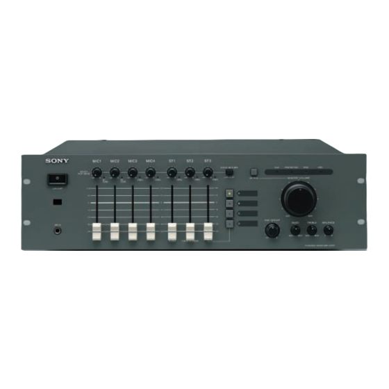
POWERED MIXER
SRP-X351P
Operating Instructions
Thank you for purchasing a Sony Powered Mixer.
Before operating, please read this manual carefully.
Be sure to keep it properly for future reference.
2001 Sony Corporation
Table of Contents
WARNING ....................................
Features .......................................
Dimensions ..................................
Block Diagrams ...........................
Specifications ..............................
Troubleshooting ..........................
2-347-110-12 (2)
2
3
4
9
11
12
13
Back Cover

Related Manuals for Sony SRP-X351P


Summary of Contents for Sony SRP-X351P
-
Page 1: Table Of Contents
Dimensions ........Block Diagrams ......Specifications ......Troubleshooting ......Back Cover Operating Instructions Thank you for purchasing a Sony Powered Mixer. Before operating, please read this manual carefully. Be sure to keep it properly for future reference. 2001 Sony Corporation... -
Page 2: Warning
Refer to them whenever you call upon servicing to qualified Class B digital device, pursuant to Part your Sony dealer regarding this product. personnel only. 15 of the FCC Rules. These limits are designed to provide reasonable Model No. -
Page 3: Features
AV input selection, master volume and MUTING can be 8 EIA standard 19 inch rackmountable (3U high) controlled. Simple work of Sony's CD player or MD player, Cassette Deck can be operated AV equipment supplied with a wireless remote control or with... -
Page 4: Location And Function Of Parts
Location and Function of Parts Front panel !¡ MIC1 MIC2 MIC3 MIC4 ECHO RETURN CLIP PROTECTION +45V ECHO/ AUX SEND ØON øOFF MASTER VOLUME MUTING SIGNAL SIGNAL SIGNAL SIGNAL SIGNAL SIGNAL SIGNAL ØON øOFF MIC GROUP BASS TREBLE BALANCE MIC4 PLAYER PLAYER/RECORDER !§... - Page 5 @£ BALANCE adjustment knob REC OUTPUT terminal; you can use without being Use to adjust the balance of left and right of the sound bothered about oscillation from signal loop. from the MASTER OUTPUT or SPEAKER terminal. SRP-X351P Recorder/Player INPUT OUTPUT When...
- Page 6 Location and Function of Parts Rear panel !¶ !¡ !™ !£ !¢ !∞ !§ 1 ANT IN (antenna input) A/B terminals 3 REMOTE terminals Use to connect the antenna for wireless tuner. When CONTROL S input terminal installing the tuner unit, connect the optional UHF Connect to the S output terminal of another equip- antenna AN-820A.
- Page 7 8 MIC input terminals (1:GND 2:HOT 4 MASTER INSERT (Tip: output, Ring: 3:COLD) input, Sleeve: GND) This is the input terminals for microphones. In MIC1 and MIC2, wireless microphone has priority These are input/output terminals for MASTER while the tuner unit is used. (Refer to page 44.) OUTPUT.
- Page 8 2 CD deck operation buttons Using this, turn it OFF when a PA system with ceiling speakers and external power amplifier. Use to operate the Sony Compact Disc Player. 3 MD deck operation buttons INSERT terminal (Tip: output, Ring: input, Sleeve: GND) Use to operate the Sony Mini Disc Recorder.
-
Page 9: Installation Of The Tuner Unit
Installation of The Tuner Unit Notes Turn off the power of this unit. Take the following precautions to prevent interference and noise. Remove the tuner cover. • If there is a TV broadcasting station nearby, to avoid possible interference from its broadcasting, do not Check the up and down sides of the tuner unit, and use that station's channel. - Page 10 Please refer to the table Sony 800MHz-band system models frequency range in the Operating Manual of Wireless Micro- phone or Transmitter. 1 GP (group) button To change the group, press the + or – button while holding this button down.
-
Page 11: Dimensions
Dimensions MIC1 MIC2 MIC3 MIC4 ECHO RETURN CLIP PROTECTION +45V ECHO/ AUX SEND ØON øOFF MASTER VOLUME MUTING SIGNAL SIGNAL SIGNAL SIGNAL SIGNAL SIGNAL SIGNAL ØON øOFF MIC GROUP BASS TREBLE BALANCE MIC4 PLAYER PLAYER/RECORDER 336 (13 1/4) 482 (19) Unit ; mm (inches) -
Page 12: Block Diagrams
Block Diagrams... -
Page 13: Specifications
Specifications AUDIO INPUT/OUTPUT SPECIFICATIONS Reference Input Name Connector Type Number of channels input output level input output level output impedance MIC IN (REAR) XLR-3-31 -54dBu -24dBu 2.2kΩ (FRONT) PHONE ST1 input Phono Jack 1(Stereo) -10dBu +20dBu 20kΩ ST2 input Phono Jack 1(Stereo) -10dBu +20dBu... -
Page 14: Troubleshooting
6.) • Are the remote control batteries dead?(See page 8.) Signal of the ST2 can not be recorded. Signal from ST2 does not output to REC OUTPUT. (See page 5.) http://www.world.sony.com/ Sony Corporation Printed in Japan Printed on recycled paper...