Table of Contents
Quick Links
Table of Contents

Related Manuals for Hitachi OPTIGEN AP 720STM


Summary of Contents for Hitachi OPTIGEN AP 720STM
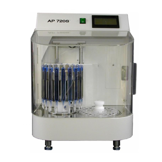
- Page 1 AP 720S LCD Panel Guide OPTIGEN® Semi-Automated Instrument...
- Page 2 The materials and information contained herein are being provided by Hitachi Chemical Diagnostics to its customer solely for customer’s use for its internal business purposes. Hitachi Chemical Diagnostics retains all rights, title, interest in and copyrights to the materials and information herein. The materials and information contained herein...
-
Page 3: Table Of Contents
Operation Key…………………………………………………………... Screen Display and Operation Method Initialization……………………………………………………… Main Menu………………………………………………………. Panel Type Selection…………………………………………….. Auto-Run (Process 1 to 7)………………………………………. Auto-Run (Photoreagent Setup and Process 8)…………………. Auto-Run (Process End)………………………………………… Maintenance……………………………………………………... Pause…………………………………………………………….. Start/End Process and Position Setup……………………………. 2-10 Alarm…………………………………………………………….. Flowchart………………………………………………………………... ― Table of Contents ―... -
Page 4: Operation Key
1 Operation Key Display: Liquid Crystal Panel Operation Key: Only the touch panel key in the shaded field is executable. Press the Operation Key to execute the function. See Figure 1. Numerical Value Input Key: Numerical value can be registered by ‘ENT’ key. If the value entered is out of the defined range, beep sounds will be on for 3 times. -
Page 5: Screen Display And Operation Method
2 Screen Display and Operation Method 2-1 Initialization [Screen Display] (Figure 3) [Summary] Figure 3 will display approximately 5 seconds after the power is turned on. Then the screen will change automatically to the initialization screen, Figure 4. After the completion of initialization, there is a beep sound and Main Menu screen, Figure 5 will display. -
Page 6: Main Menu
2 Screen Display and Operation Method 2-2 Main Menu [Screen Display] (Figure 5) [Summary] Figure 5 is the Main Menu screen after completion of Figure 4. Panel 36 is the default panel. Figure 6 is the Main Menu screen after selecting Panel 20 in Figure 7. [Operation Key] Panel 36: To Figure 7 Panel Type Selection screen... -
Page 7: Panel Type Selection
2 Screen Display and Operation Method 2-3 Panel Type Selection [Screen Display] (Figure 7) [Summary] Select 36-allergen or 20-allergen panel in Figure 7. [Operation Key] To Figure 5 Main Menu screen To Figure 6 Main Menu screen... -
Page 8: Auto-Run (Process 1 To 7)
2 Screen Display and Operation Method 2-4 Auto-Run (Process 1 to Process 7) [Screen Display] (Figure 8) (Figure 9) (Figure 10) (Figure 12) (Figure 13) (Figure 11) (Figure 14) (Continued on next page) - Page 9 (Auto-Run, cont.) [Summary] Figure 8 is a confirmation screen. The Operator needs to check that the Wash Buffer Bottle and Antibody Reservoir are filled, and that the Waste Bottle is emptied prior to the Auto-Run. Press “Start” key. The following screens will be displayed in order and Auto-Run will be executed: o Figure 9 displays the priming is in process.
-
Page 10: Auto-Run (Photoreagent Setup And Process 8)
2 Screen Display and Operation Method 2-5 Auto-Run (Photoreagent Setup and Process 8) [Screen Display] (Figure 15) (Figure 16) [Summary] Figure 15 will alarm Operator that Photoreagent is needed. The display shows the elapsed time from the start of auto-pause. “Alarm Off” key will stop the alarm. “Continue”... -
Page 11: Auto-Run (Process End)
2 Screen Display and Operation Method 2-6 Auto-Run (Process End) [Screen Display] (Figure 18) [Summary] Figure 18 will alarm the Operator of the completion of Auto-Run. The display shows the elapsed time from the completion of Auto-Run. “Alarm Off” key will stop the alarm. -
Page 12: Maintenance
2 Screen Display and Operation Method 2-7 Maintenance [Screen Display] (Figure 19) (Figure 20) (Figure 22) (Figure 24) (Figure 26) (Figure 21) (Figure 23) (Figure 25) (Continued on next page) - Page 13 (Maintenance, cont.) [Summary] Figure 19 provides the Prime, Rinse and Clock functions. [Operation Key] (Figure 19) Prime: To Figure 20 Prime Operation screen Rinse: To Figure 22 Rinse Operation screen Clock: To Figure 26 Time Setup screen Back: To Figure 5 Main Menu screen (Figure 20) Prior to Prime Operation, the Operator needs to set the Wash Buffer tube into the Wash Buffer Bottle, the water tube into the Deionized Water Bottle, &...
-
Page 14: Pause
2 Screen Display and Operation Method 2-8 Pause [Screen Display] (Figure 27) (Figure 29) (Figure 31) (Figure 33) (Figure 34) (Figure 28) (Figure 30) (Figure 32) (Continued on next page) - Page 15 (Pause, cont.) [Summary] Figure 27 to Figure 33 the alarm will indicate that the current operation is paused. The screen will display the [Run Status] including the time elapsed from the start of the pause. A message “Information=” may be displayed in the screen, Figure 33. See [Supplement] below for details.
- Page 16 (Examples of alarm messages, cont.) o Example) “Information =C2 L” “C2 L” indicates failure from the head part of top/bottom carrier drive or sensor failure. After you confirm the status, press “CONTINUE” key and check the status. o Example) “Information =C2 H” “C2 H”...
-
Page 17: Start/End Process And Position Setup
2 Screen Display and Operation Method 2-9 Start/End Process and Position Setup [Screen Display] Start Process [Summary] Figure 35 will appear when power interruption occurs during Auto-Run or the current process is cancelled/paused during Auto-Run. Before re-starting the Auto-Run, the Operator needs to setup the START PROCESS NO., END PROCESS NO. -
Page 18: Alarm
2 Screen Display and Operation Method 2-10 Alarm [Summary] The alarm screen will appear when a problem occurs during the Auto-Run. The alarm will sound and can be stopped by pressing the “Alarm Off” key. There are two kinds of alarm screens. The first alarm screen is for confirmation. The Operator will confirm the failure or error displayed on the screen. - Page 19 Figure 37 - Alarm Screen of Data Initialization (Confirmation) [Screen Display] (Figure 37) [Summary] Figure 37 shows data error has occurred after initialization. The Operator needs to press “Ok” so that the data for the instrument will be recovered and the default values will be implemented.
- Page 20 Figure 39 - Alarm Screen of No Pettes [Screen Display] (Figure 39) [Summary] If the control software detects that there is no pette at the start of the run, Figure 39 will appear. If the run needs to be continued, setup pettes in the Pette Rack, and press ‘Retry’...
- Page 21 Figure 41 - Alarm Screen of Wrong Start Pette Setup [Screen Display] (Figure 41) [Summary] If the control software detects that the position of the start pette is wrong at the start of the run, Figure 41 will appear. If the run needs to be continued, setup the pettes correctly, press ‘Retry’...
-
Page 22: Flowchart
Pause AP720S™ Panel Flowchart Auto-Run Maintenance Interrupted run...