Table of Contents
- 1 Table of Contents
- 2 Safety Precautions
- 3 Installation Location
- 4 Installing the Outdoor Unit
- 5 Installing the Refrigerant Piping
- 6 Drainage Piping Work
- 7 Caution
- 8 Electrical Work
- 9 Test Run
- 10 Initial Settings for Refrigerant Leakage Detection Function
- 11 Special Functions
- 12 System Control (Fig. 10-1)
Table of Contents

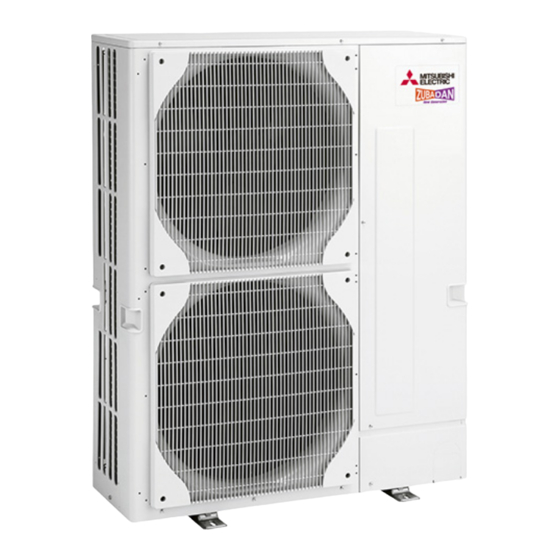
Summary of Contents for Mitsubishi Electric PUHZ-RP HA5
- Page 1 Air-Conditioners PUHZ-RP • PUHZ-RP • INSTALLATION MANUAL FOR INSTALLER English For safe and correct use, read this manual and the indoor unit installation manual thoroughly before installing the air-conditioner unit.
-
Page 2: Table Of Contents
Contents 1. Safety precautions.......... 6. -
Page 3: Safety Precautions
1. Safety precautions 1.3. Before electric work Caution: • B e sure to install circuit breakers. If not installed, electric shock may re- • Be sure to ground the unit. Do not connect the ground wire to gas or water sult. pipes, lightning rods, or telephone grounding lines. If the unit is not prop- • F or the power lines, use standard cables of sufficient capacity. Otherwise, erly grounded, electric shock may result. - Page 4 2. Installation location ■ ■ 2.2. Choosing the outdoor unit installation location RP71 RP100 - 200 • Avoid locations exposed to direct sunlight or other sources of heat. • Select a location from which noise emitted by the unit will not inconvenience neighbors.
-
Page 5: Installing The Outdoor Unit
3. Installing the outdoor unit • Be sure to install the unit in a sturdy, level surface to prevent rattling noises (mm) during operation. (Fig. 3-1)Foundation bolt M10 (3/8") Thickness of concrete 10 mm Length of bolt 70 mm Weight-bearing capacity 30 kg... - Page 6 4. Installing the refrigerant piping 4.2. Connecting pipes (Fig. 4-1) 45°± 2 ° • When commercially available copper pipes are used, wrap liquid and gas pipes with commercially available insulation materials (heat-resistant to 100 °C or more, thickness of 1 mm or more). • The indoor parts of the drain pipe should be wrapped with polyethylene foam insulation materials (specific gravity of 0.03, thickness of 9 mm or more).
- Page 7 4. Installing the refrigerant piping 4.4. Refrigerant pipe airtight testing method (Fig. 4-5) (1) Connect the testing tools. • Make sure the stop valves A B are closed and do not open them. • Add pressure to the refrigerant lines through the service port C of the liquid stop valve A . () Do not add pressure to the specified pressure all at once;...
- Page 8 4. Installing the refrigerant piping Maximum pipe length (RP170·RP200) Liquid O.D. 9.52 12.7 15.88 pipe Thick- t0.8 t0.8 t1.0 (mm) ness O.D. 22.2 25.4 28.58 22.2 25.4 28.58 22.2 25.4 28.58 31.75 pipe Thick- t1.0 t1.0 t1.0 t1.0 t1.0 t1.0 t1.0 t1.0 t1.0 t1.1 (mm) ness Standard size...
-
Page 9: Drainage Piping Work
4. Installing the refrigerant piping 4.7. Precautions when reusing existing R22 refrigerant pipes • Refer to the flowchart below to determine if the existing pipes can be used and if it is necessary to use a filter dryer. • If the diameter of the existing pipes is different from the specified diameter, refer to technological data materials to confirm if the pipes can be used. Measure the existing pipe thickness and check for damage. -
Page 10: Electrical Work
6. Electrical work 6.1. Outdoor unit (Fig. 6-1, Fig. 6-2) 1 Remove the service panel. RP71-170V 2 Wire the cables referring to the Fig. 6-1 and the Fig. 6-. * Except PEA-RP170, 00WHA S1 S2 S3 A Indoor unit B Outdoor unit C Remote controller RP100-200Y D Main switch (Breaker) E Earth L1 L2 L3 N S1 S2 S3... - Page 11 6. Electrical work 6.2. Field electrical wiring RP71V RP100,15V RP140, 170V RP100, 15, 140Y RP170, 00Y Outdoor unit model 3N~ (3 ph 4-wires), 3N~ (3 ph 4-wires), Outdoor unit power supply ~/N (single), 50 Hz, 30 V ~/N (single), 50 Hz, 30 V ~/N (single), 50 Hz, 30 V 50 Hz, 400 V 50 Hz, 400 V Outdoor unit input capacity Main switch (Breaker)
-
Page 12: Test Run
7. Test run 7.1. Before test run • The insulation resistance drops due to accumulation of refrigerant in the com- pressor. The resistance will rise above 1 M" after the compressor is warmed ► A fter completing installation and the wiring and piping of the indoor and up for 4 hours. outdoor units, check for refrigerant leakage, looseness in the power sup- (The time necessary to warm up the compressor varies according to atmo- ply or control wiring, wrong polarity, and no disconnection of one phase in spheric conditions and refrigerant accumulation.) -
Page 13: Initial Settings For Refrigerant Leakage Detection Function
8. Initial settings for refrigerant leakage detection function Remote control button positions This air conditioner (outdoor unit) can detect refrigerant leakage which may happen during a long period of use. In order to enable the leakage detection, the following settings are required to let the unit memorize the initial conditions (initial learning). * Except RP170, 00. -
Page 14: System Control (Fig. 10-1)
9. Special Functions 3 Because the unit automatically stops in about to 3 minutes after the refrigerant 9.3. Refrigerant collecting (pump down) collecting operation (LED1 and LED are lit), be sure to quickly close the gas Perform the following procedures to collect the refrigerant when moving the indoor stop valve. - Page 15 Unit : mm Fig. 2-6 Fig. 2-7 Fig. 2-8 Fig. 2-9 1500 (1000) 500 (300) Fig. 2-10 Fig. 2-11 Fig. 2-12 Fig. 2-13 Fig. 2-14 Fig. 2-15 Fig. 2-16 Fig. 2-17 Fig. 2-18...
- Page 16 This product is designed and intended for use in the residential, commercial and light-industrial environment. HEAD OFFICE: TOKYO BLDG., 2-7-3, MARUNOUCHI, CHIYODA-KU, TOKYO 100-8310, JAPAN RG79U640L0 Printed in Japan...


