Honeywell QuantumT 3580 User Manual
Omnidirectional laser scanner
Hide thumbs
Also See for QuantumT 3580:
- User manual (60 pages) ,
- Quick start manual (45 pages) ,
- User manual (61 pages)
Table of Contents
Table of Contents

Related Manuals for Honeywell QuantumT 3580


Summary of Contents for Honeywell QuantumT 3580
- Page 1 ® QuantumT 3580 Omnidirectional Laser Scanner User’s Guide...
- Page 2 Disclaimer Honeywell International Inc. (“HII”) reserves the right to make changes in specifications and other information contained in this document without prior notice, and the reader should in all cases consult HII to determine whether any such changes have been made. The information in this publication does not represent a commitment on the part of HII.
-
Page 3: Table Of Contents
ABLE OF ONTENTS Introduction Product Overview ..................... 1 Scanner and Accessories ................. 2 Maintenance ..................... 3 Scanner Components ..................4 Caution and Serial Number Labels ..............5 Cable Removal ....................5 Mounting Specifications and Stand Assembly ..........6 Installation RS232, RS232 TTL, Light Pen or Laser Emulation .......... 8 RS485 ...................... - Page 4 ABLE OF ONTENTS Design Specifications ..................31 Applications and Protocols ................. 33 Default Settings - Communication Parameters ........... 34 Configuration Modes ..................39 Upgrading the Firmware ..................40 Scanner and Cable Terminations Scanner Pinout Connections ................41 Cable Connector Configurations (Host End) ..........43 Regulatory Compliance ..................
-
Page 5: Product Overview
® single-line scanning capabilities. It utilizes the powerful Honeywell QuantumE scan engine to provide an outstanding scan performance on all standard 1D barcode symbologies, including GS1 DataBar™ (RSS). This fully enclosed scanner includes large easily visible LEDs and a rugged protective boot with an adjustable stand. -
Page 6: Scanner And Accessories
NTRODUCTION Scanner and Accessories ASIC OMPONENTS Part No. Description MS3580 QuantumT Omni \ Single-Line Scanner QuantumT Omni \ Single-Line Scanner 00-02026 Installation and User’s Guide * ® 00-02407 MetroSelect Configuration Guide * * Guides also available for download at www.honeywellaidc.com. PTIONAL CCESSORIES Part No. -
Page 7: Maintenance
NTRODUCTION Scanner and Accessories PTIONAL CCESSORIES Part No. Description Keyboard Wedge PowerLink Cable 54-54002x-3 straight cord, short strain relief Stand Alone Keyboard PowerLink Cable 54-54020x-3 straight cord, short strain relief ™ USB Full Speed Cable, Locking Plus-Power Type A 54-54213x-N-3 straight cord, short strain relief ™... -
Page 8: Scanner Components
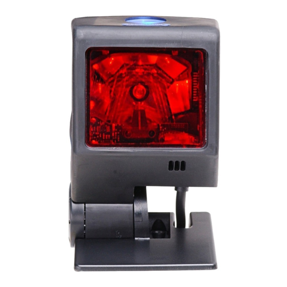
NTRODUCTION Scanner Components Figure 1. Scanner Components ESCRIPTION Red Output Window (Laser Aperture) Pin Hole for Cable Release 10-Pin RJ45, Female Socket Speaker Blue and White LED Indicators Button Protective Boot and Stand Connection Never remove the protective boot from the MS3580. Removing the protective boot will expose electrical components of the scanner that are highly susceptible to electrostatic discharge (ESD). -
Page 9: Caution And Serial Number Labels
NTRODUCTION Caution and Serial Number Labels Figure 2. Labeling Example Caution To maintain compliance with applicable standards, all circuits connected to the scanner must meet the requirements for SELV (Safety Extra Low Voltage) according to EN/IEC 60950-1. To maintain compliance with standard CSA C22.2 No. 60950-1/UL 60950-1 and norm EN/IEC 60950-1, the power source should meet applicable performance requirements for a limited power source. -
Page 10: Mounting Specifications And Stand Assembly
NTRODUCTION Mounting Specifications and Stand Assembly Pedestal Stand Figure 4. Pedestal Stand Assembly Optional Flex Stand Figure 5. Assembly Components for Optional Flex Stand Item Description Qty. Item Description MS3580, QuantumT Flexible Shaft* Pivot Cylinder Base Plate Cover Bearing Plate #8 x 1.00"... - Page 11 NTRODUCTION Mounting Specifications and Stand Assembly Optional Flex Stand Figure 6. Mounting Hole Detail for the Flex Stand Base Plate (Optional) Figure 7. Assembling the Optional Flex Stand...
-
Page 12: Installation
NSTALLATION RS232, RS232 TTL, Light Pen or Laser Emulation Turn off the host device. Plug the male 10-pin RJ45 end of the PowerLink cable into the 10-pin socket on the MS3580. Connect the 9-pin female end of the PowerLink cable to the host device. Plug the external power supply into the power jack on the PowerLink cable. -
Page 13: Rs485
NSTALLATION RS485 Turn off the host device. Plug the male 10-pin RJ45 end of the MVC cable into the 10-pin socket on the MS3580. Connect the other end of the MVC cable to the host device. Turn on the host device. Figure 9. -
Page 14: Keyboard Wedge
Not all computers supply the same current through the keyboard port. For this reason, Honeywell recommends using an external power supply. For additional information contact a customer service representative. -
Page 15: Stand-Alone Keyboard Wedge
Not all computers supply the same current through the keyboard port. For this reason, Honeywell recommends using an external power supply. For additional information contact a customer service representative. -
Page 16: Usb (Integrated)
NSTALLATION Turn off the host device. Plug the male 10-pin RJ45 end of the USB cable into the 10-pin socket on the MS3580. Plug the other end of the USB interface cable into the host device’s USB port. Turn on the host device. Figure 12. -
Page 17: Scanner Operation
CANNER PERATION Configurable Primary and Single Line Scan Pattern Modes There are two configurable scan pattern modes available with the MS3580. • The primary scan pattern mode is the default scan pattern active when the scanner starts. • The single line scan pattern mode is activated by pressing the button located on the side of the scanner. - Page 18 CANNER PERATION Configurable Button Functions INGLE ATTERN UTTON LICK ODE WITH NABLED For illustration purposes the unit’s primary scan pattern has been set to all scan lines (omnidirectional reading) and the single line pattern has been set to single-line (menu reading) with a 5 second button click timeout configured.
- Page 19 CANNER PERATION Configurable Button Functions INGLE ATTERN UTTON LICK ODE WITH ISABLED For illustration purposes the unit’s primary scan pattern has been set to all scan lines (omnidirectional reading) and the single line pattern has been set to single-line (menu reading) with a 5 second button click timeout configured.
- Page 20 CANNER PERATION Configurable Button Functions INGLE ATTERN UTTON ODE WITH NABLED For illustration purposes the unit’s* primary scan pattern has been set to all scan lines (omnidirectional reading) and the single line pattern has been set to single-line (menu reading) with a 5 second button click timeout configured.
- Page 21 CANNER PERATION Configurable Button Functions To scan and transmit additional bar codes, repeat steps 2 through 4. The primary scan pattern will automatically reactivate after the button is released and no bar code is present in the scan field.
- Page 22 CANNER PERATION Configurable Button Functions ECONDARY ATTERN UTTON ODE WITH ISABLED For illustration purposes the unit’s* primary scan pattern has been set to all scan lines (omnidirectional reading) and the secondary pattern has been set to single-line (menu reading) with a 5 second button click timeout configured.
-
Page 23: Audible Indicators
CANNER PERATION Audible Indicators When the MS3580 is in operation, it provides audible feedback to indicate the status of the scanner. Eight settings are available for the tone of the beep (normal, 6 alternate tones and no tone). For instructions on how to change the tone of the beeper, refer to the MetroSelect Configuration Guide (00-02407). -
Page 24: Visual
CANNER PERATION Visual Indicators The QuantumT is equipped with a blue and white LED that indicates the scanner’s state and the status of the current scan when the unit is in operation. Figure 13. Speaker Location and LED Location No LEDs The LEDs will not be illuminated if the scanner is not receiving power from the host or transformer. -
Page 25: Failure
CANNER PERATION Failure Mode Indicators Flashing Blue and One Razzberry Tone This indicates that the scanner has experienced a laser subsystem failure. Return the unit to an authorized service center for repair. Flashing Blue and White and Two Razzberry Tones This indicates that the scanner has experienced a motor failure. -
Page 26: Depth Of Field Specifications
CANNER PERATION Depth of Field Specifications* Normal Scan Zone Specifications are based on a 0.33 mm (13 mil) bar code. † Figure 14. MS3580 Normal Depth of Field * All specifications are subject to change without notice. † MS3580 shown with pedestal stand. -
Page 27: Reduced Scan Zone
CANNER PERATION Depth of Field Specifications* Reduced Scan Zone Specifications are based on a 0.33 mm (13 mil) bar code. † Figure 15. MS3580 Reduced Depth of Field * All specifications are subject to change without notice. † MS3580 shown with pedestal stand. -
Page 28: Depth Of Field By Bar Code Element Width
CANNER PERATION Depth of Field by Bar Code Element Width* Normal Scan Zone INIMUM LEMENT IDTH mils Figure 16. Normal Scan Zone by Bar Code Element Width * All specifications are subject to change without notice. -
Page 29: Reduced Scan Zone
CANNER PERATION Depth of Field by Bar Code Element Width* Reduced Scan Zone INIMUM LEMENT IDTH mils Figure 17. Reduced Scan Zone by Bar Code Element Width * All specifications are subject to change without notice. -
Page 30: Ir Activation Range
CANNER PERATION IR Activation Range* † QuantumT‘s default power save mode is Laser OFF. This power save mode turns the laser off after a configured period of non-use. Any movement detected by the IR in the activation area will cause the scanner to exit power save mode. The laser will automatically turn back on preparing the scanner for bar code recognition, decoding and transmission. -
Page 31: Troubleshooting Guide
ROUBLESHOOTING UIDE The following guide is for reference purposes only. Contact a Honeywell representative to preserve the limited warranty terms on page 48. Symptoms Possible Cause(s) Solution All Interfaces Check the transformer, outlet The unit has no No power is being and power strip. - Page 32 ROUBLESHOOTING UIDE Symptoms Possible Cause(s) Solution All Interfaces The unit scans If the scanner is setup to support The scanner is a bar code, but ACK/NAK, RTS/CTS, configured to support locks up after XON/XOFF or D/E, verify that some form of host the first scan the host cable and host are handshaking but is not...
- Page 33 ROUBLESHOOTING UIDE Symptoms Possible Cause(s) Solution All Interfaces During power There is a non-volatile up the unit Contact a service representative. RAM failure. beeps 3 times. During power up the unit There is a RAM or Contact a service representative. razzes ROM failure.
- Page 34 ROUBLESHOOTING UIDE Symptoms Possible Cause(s) Solution RS232 Only The host is The scanner and host Check that the scanner and the receiving data may not be configured host are configured for the same but the data does for the same interface. interface.
-
Page 35: Design Specifications
ESIGN PECIFICATIONS MS3580 Operational Normal Depth of Field: 19 mm - 273 mm (.75"- 10.75") 0.33 mm (13 mil) bar code Reduced Depth of Field: 19 mm - 146 mm (.75"- 5.75") Omni Scan Scan Speed: 1650 scan lines per second No. - Page 36 ESIGN PECIFICATIONS MS3580 Mechanical Width: 63 mm (2.48") Depth: 50 mm (1.97") Height: 68 mm (2.68") Weight: 6 oz (170 g) Electrical Voltage Supply: 5VDC ± 0.25V Operating Power: 1.375 W Standby Power: 1.0 W Operating Current: 275 mA typical at 5VDC Standby Current: 230 mA typical at 5VDC DC Transformers:...
-
Page 37: Applications And Protocols
The MS3580 scanner with built-in PC Keyboard Wedge Interface is designed to be used for keyboard emulation only. Many RS232 configurable functions (e.g. formatting) available in other Honeywell scanners are also available as keyboard wedge functions. The following are the most important selectable options specific to the keyboard wedge. -
Page 38: Default Settings - Communication Parameters
EFAULT ETTINGS OMMUNICATION ARAMETERS Many functions of the scanner can be "configured" - that is enabled or disabled. The scanner is shipped from the factory configured to a set of default conditions. The default parameter of the scanner has an asterisk ( * ) in the charts on the following pages. - Page 39 EFAULT ETTINGS OMMUNICATION ARAMETERS RS232* IGHT ASER RS485 KBW ARAMETER EFAULT RS232 MULATION Expanded ID “]e0” RSS Limited Enable RSS Limited ID “]e0” ...
- Page 40 EFAULT ETTINGS OMMUNICATION ARAMETERS RS232* IGHT ASER RS485 KBW ARAMETER EFAULT RS232 MULATION Transmit UPC-A Check Digit Transmit UPC-E ...
- Page 41 EFAULT ETTINGS OMMUNICATION ARAMETERS RS232* IGHT ASER RS485 KBW ARAMETER EFAULT RS232 MULATION Nixdorf ID LRC Enabled UPC Prefix ...
- Page 42 EFAULT ETTINGS OMMUNICATION ARAMETERS RS232* IGHT ASER RS485 KBW ARAMETER EFAULT RS232 MULATION Supplements are not Required Two Digit Redundancy ...
-
Page 43: Configuration Modes
ONFIGURATION ODES The MS3580 Series scanner has three modes of configuration. • Bar Codes The MS3580 can be configured by scanning the bar codes included in the Single-Line Configuration Guide or the Supplemental Configuration Guide. The manuals are available for download at www.honeywellaidc.com. •... -
Page 44: Upgrading The Firmware
PGRADING THE IRMWARE The MS3580 is part of Honeywell’s line of scanners with flash upgradeable firmware. The upgrade process requires a new firmware file supplied to the customer by a customer service representative and Honeywell’s MetroSet2 software . A personal computer running Windows 95 or greater with an available RS232 serial or USB port is also required to complete the upgrade. -
Page 45: Scanner And Cable Terminations
CANNER AND ABLE ERMINATIONS Scanner Pinout Connections The MS3580 scanner interfaces terminate to a 10-pin modular socket. The serial # label indicates the interface enabled when the scanner is shipped from the factory. Figure 19. Bottom View of MS3580 (Stand Removed) MS3580-47 Keyboard Wedge MS3580-41 and Stand-Alone Keyboard... - Page 46 CANNER AND ABLE ERMINATIONS MS3580-11 RS485 Function Ground RS232 Transmit Output RS232 Receive Input RTS Output CTS Input DTR Input IBM B-Transmit IBM A+ Receive +5VDC Shield Ground MS3580-104 RS232 TTL, Laser Emulation Function Ground RS232 Transmit Output RS232 Receive Input RTS Output (TTL RS232) / Flip Sense CTS Input (TTL RS232) / Trigger Emulation Output DTR Input (TTL RS232) / Scan Enable...
-
Page 47: Cable Connector Configurations (Host End)
CANNER AND ABLE ERMINATIONS Cable Connector Configurations (Host End) “Standard” PowerLink Cable 59-59000 -3 straight MLPN Function Shield Ground RS232 Transmit Output RS232 Receive Input DTR Input/Light Pen Source Power/Signal Ground Light Pen Data CTS Input 9-Pin D-Type Connector RTS Output +5VDC USB Power/Communication Cable 54-54213... - Page 48 PC Clock No Connect Honeywell will supply an adapter cable with a 5-pin DIN male connector on one end and a 6-pin mini DIN female connector on the other. According to the termination required, connect the appropriate end of the adapter cable to the PowerLink cable, leaving the necessary termination exposed for connecting to the keyboard and the keyboard port on the PC.
-
Page 49: Regulatory Compliance
EGULATORY OMPLIANCE Safety ITE Equipment IEC 60950-1: 2005+A11, EN 60950-1:2006+A11 Laser Laser Class 1: IEC 60825-1:2007+A1+A2, EN 60825-1:2007+A1+A2 Caution Use of controls or adjustments or performance of procedures other than those specified herein may result in hazardous laser light exposure. Under no circumstances should the customer attempt to service the laser scanner. - Page 50 EGULATORY OMPLIANCE Emissions FCC Part 15, ICES-003, CISPR 22, EN 55022 Immunity CISPR 24, EN 55024 NOTE: Immunity performance is not guaranteed for scanner cables greater than 3 meters in length when fully extended. Changes or modifications not expressly approved by the party responsible for compliance could void the user’s authority to operate the equipment.
- Page 51 EGULATORY OMPLIANCE Changes or modifications not expressly approved by the party responsible for compliance could void the user’s authority to operate the equipment. Standard Europeo Attenzione Questo e’ un prodotto di classe A. Se usato in vicinanza di residenze private potrebbe causare interferenze radio che potrebbero richiedere all’utilizzatore opportune misure.
-
Page 52: Limited Warranty
IMITED ARRANTY Honeywell International Inc. ("HII") warrants its products and optional accessories to be free from defects in materials and workmanship and to conform to HII’s published specifications applicable to the products purchased at the time of shipment. This warranty does not cover any HII product which is (i) improperly installed or used;... - Page 53 IMITED ARRANTY All provisions of this Limited Warranty are separate and severable, which means that if any provision is held invalid and unenforceable, such determination shall not affect the validity of enforceability of the other provisions hereof. Use of any peripherals not provided by the manufacturer may result in damage not covered by this warranty.
-
Page 54: Patents
ATENTS For patent information, please refer to www.honeywellaidc.com/patents. -
Page 55: Indicators Audible
NDEX Emissions ........46 AC ........2, 8–12 Accessories ....... 2, 3 Adapter ........10 Failure Audible Indicator . 13, 19–21, 27–30, Modes........21 Firmware ........40 Flash ROM ......1, 40 Bar Code ..19–21, 27–30, 31, 39 Bar Width ........31 Host ........ - Page 56 NDEX Scan Pattern ......1, 31 Horizontal Raster ..... 13 Maintenance ........3 Omnidirectional ....13–18 Manual....... 2, 19, 33 Primary ......13–18 Meteor ......... 40 Single Line ......13–18 MetroSelect ......... 39 Single-Line ......13–18 MetroSet2 ........40 Scan Speed ........ 31 Mode of Operation SELV ........
-
Page 57: Customer Support
E-mail: [email protected] Brazil Telephone: +55 (11) 5185-8222 Fax: +55 (11) 5185-8225 E-mail: [email protected] Mexico Telephone: 01-800-HONEYWELL (01-800-466-3993) E-mail: [email protected] Europe, Middle East, and Africa Telephone: +31 (0) 40 7999 393 Fax: +31 (0) 40 2425 672 E-mail: [email protected] Hong Kong... -
Page 58: Product Service And Repair
USTOMER UPPORT Product Service and Repair Honeywell International Inc. provides service for all its products through service centers throughout the world. To obtain warranty or non-warranty service, contact the appropriate location below to obtain a Return Material Authorization number (RMA #) before returning the product. - Page 59 USTOMER UPPORT Online Product Service and Repair Assistance You can also access product service and repair assistance online at www.honeywellaidc.com.
- Page 60 Honeywell Scanning & Mobility 9680 Old Bailes Road Fort Mill, SC 29707 www.honeywellaidc.com 00-05090 Rev E 11/10...