C7915A Infrared Flame Detector
APPLICATION
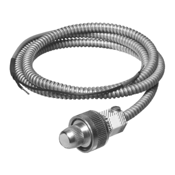
The C7915A Flame Detector includes a lead sulfide photocell
that is sensitive to the infrared radiation emitted by the
combustion of fuels such as natural gas, oil, and coal.
• Particularly suitable for combination or dual-fuel
applications.
• When installed properly, can supervise the pilot flame and/
or the main burner flame.
• Mounts easily on a standard 3/4 inch sight pipe.
• The infrared sensor plugs into an electrical socket in the
C7915A assembly and is field replaceable.
• The lead sulfide photocell's sensitivity to infrared radiation
is compatible with a wide range of flame supervisory
applications.
• Flexible metal cable protects and electrically shields the
detector coaxial cables.
• Accessories available include a heat block, seal-off
adapter, reducer bushing, and orifice plate.
• Immune to x-ray testing.
SPECIFICATIONS
STANDARD MODELS
MODELS: See Table 6 for flame safeguard controls and asso-
ciated amplifiers.
DETECTOR RESPONSE: Responds to infrared radiation with
wavelengths between 0.75 and 1.0 micron.
LEAD SULFIDE PHOTOCELL: Photo conductor resistance
decreases as incident radiant energy increases.
AMBIENT TEMPERATURE RATING: -40°F to 125°F (-40°C to
52°C) maximum at the lead sulfide photocell.
MOUNTING:
C7915A Mount-knurled collar with 3/4-14 NPSM internal
threads for mounting on a standard 3/4 in. pipe (see Fig. 1).
32007255-001 Lead Sulfide Photocell-two leads for inserting
into socket in C7915A (see Fig. 8).
Application ........................................................................
Specifications ...................................................................
Ordering Information ........................................................
Operation ..........................................................................
Installation ........................................................................
Wiring ...............................................................................
Adjustments and Checkout ............................................... 10
Troubleshooting ................................................................ 11
PRODUCT DATA
Contents
1
1
2
3
3
8
65-0292-06
Table of Contents

Related Manuals for Honeywell C7915A


Summary of Contents for Honeywell C7915A
-
Page 1: Table Of Contents
APPLICATION LEAD SULFIDE PHOTOCELL: Photo conductor resistance decreases as incident radiant energy increases. The C7915A Flame Detector includes a lead sulfide photocell AMBIENT TEMPERATURE RATING: -40°F to 125°F (-40°C to that is sensitive to the infrared radiation emitted by the 52°C) maximum at the lead sulfide photocell. -
Page 2: Ordering Information
TRADELINE® Catalog or price sheets for complete ordering number. If you have additional questions, need further information, or would like to comment on our products or services, please write or phone: 1. Your local Honeywell Environmental and Combustion Controls Sales Office (check white pages of your phone directory). 2. Honeywell Customer Care... -
Page 3: Operation
3/4 - 14 NPSM INTERNAL THREADS REPLACING A FIREYE LEAD SULFIDE DETECTOR M23448A Fig. 1. Mounting dimensions of C7915A Infrared Flame Detector and accessories, in inches. (mm). OPERATION CELL CONSTRUCTION The photosensitive material used in the infrared detector is OPERATION OF INFRARED lead sulfide. -
Page 4: Field Of View
All wiring must be NEC Class 1 (line voltage). A Swivel Mount (Honeywell part no. 118367A) is available to Use the C7915A only with Honeywell lead sulfide facilitate flame sighting after the C7915A is mounted. - Page 5 An orifice plate with a hexagonal orifice diameter of 0.125 in. the photocell to a 0.125 in. (3.175 mm) diameter orifice is 4 in. (3.2 mm) is supplied with the C7915A Infrared Flame Detector. (101.6 mm), and from the orifice to the flame junction (or The orifice can be mounted in front of the cell in the seal-off refractory) is 36 in.
-
Page 6: Over
C7915A INFRARED FLAME DETECTOR WITHOUT ORIFICE PLATE WITH ORIFICE PLATE PILOT HOT REFRACTORY MAIN FLAME PILOT HOT REFRACTORY MAIN FLAME M3050B Fig. 3. Using orifice plate to restrict detector field of view to intersection of pilot and main flame, or to small area of hot refractory. -
Page 7: Installing The Sight Pipe
Generally, it is desirable to have the sight Fig. 4. C7915A Infrared Flame Detector aimed at side wall of pipe tilting downward to prevent soot or dirt buildup. -
Page 8: Wiring
C7915A INFRARED FLAME DETECTOR SWIVEL MOUNT Mount the C7915A Detector onto the sight pipe, heat block, or other accessory (Fig. 1 and 9). Screw the mounting collar onto To facilitate flame sighting, a Swivel Mount (part no. 118367A) the sight pipe or accessory. - Page 9 , use Honey- M23446A well specification no. R1298020 or equivalent for the F Fig. 10. Typical wiring of C7915A Infrared Flame Detector to coaxial cable. (This wire is rated up to 400°F [204°C] for nearby wiring subbase or terminal strip.
-
Page 10: Adjustments And Checkout
C7915A INFRARED FLAME DETECTOR ADJUSTMENTS AND Move the detector and sight pipe around to sight the flame at various positions and angles. Try to get a maximum steady CHECKOUT meter reading. The signal must be above the minimum acceptable current/voltage listed in Table 6. -
Page 11: Troubleshooting
EQUIPMENT REQUIRED IGNITION INTERFERENCE TEST 1. Voltmeter (Honeywell W136A or equivalent) with 0 to 300 Vac scale. It is possible for infrared amplifiers to respond to ignition spark 2. A one megohm/volt meter with a zero to 5 or 10 Vdc scale is recommended for 7800 SERIES, R7140 control electrical noise (interference) under certain conditions. -
Page 12: Periodic Maintenance
• add a shield or screen to reflect radiated heat away If the C7915A is disassembled for any reason (e.g., to from the detector. replace the lead sulfide cell or bushing with focusing •...