Table of Contents
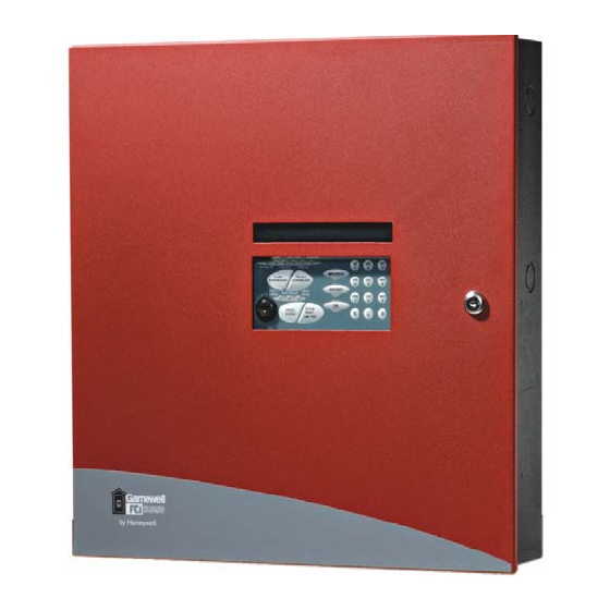
7100 Series Fire Alarm Control
Installation/Operating Manual
Document: 9000-0447
Print Date: 6/6/07
Rev. I
P/N 9000-0447 Rev. I ECN: 06-528
Copyright © 1998
Honeywell International Inc.
All Rights Reserved
Published in U.S.A.
12 Clintonville Road, Northford, CT 06472-1610 USA • TEL: (203) 484-7161 • FAX: (203) 484-7118
www.gamewell-fci.com
Table of Contents

Related Manuals for Honeywell Gamewell 7100 Series


Summary of Contents for Honeywell Gamewell 7100 Series
- Page 1 Document: 9000-0447 Print Date: 6/6/07 Rev. I P/N 9000-0447 Rev. I ECN: 06-528 Copyright © 1998 Honeywell International Inc. All Rights Reserved Published in U.S.A. 12 Clintonville Road, Northford, CT 06472-1610 USA • TEL: (203) 484-7161 • FAX: (203) 484-7118 www.gamewell-fci.com...
-
Page 2: Fire Alarm System Limitations
Do not over-tighten screw terminals. Over- Authority Having Jurisdiction. tightening may damage threads, resulting in E3 Series™ is a trademark of Honeywell International Inc. 9000-0447 Rev. I... - Page 3 reduced terminal contact pressure and difficulty MAINTENANCE: with screw terminal removal. Disconnect all To keep your fire alarm system in excellent sources of power before servicing, removing, or working order, ongoing maintenance is required inserting any circuit boards. Control unit and per the manufacturer’s recommendations and UL associated equipment may be damaged by and NFPA Standards, and applicable state and...
- Page 4 • Smoke particles may be blown away from signal. It is the property owner's responsibility to conduct fire drills and other training exercise to detectors by air outlets. make people aware of fire alarm signals and • Smoke particles may be drawn into air returns instruct them on the proper reaction to alarm before reaching the detector.
-
Page 5: Installation Precautions
Installation Precautions Adherence to the following will aid in problem-free installation with long-term reliability: WARNING - Several different sources of initiating and indicating device loops. Most power can be connected to the fire alarm devices cannot tolerate more than a 10% I.R. control panel. - Page 6 • Brief description of content you think should be improved or corrected • Your suggestion for how to correct/improve documentation Send email messages to: [email protected] Please note this email address is for documentation feedback only. If you have any technical issues, please contact Technical Services.
-
Page 7: Table Of Contents
TABLE OF CONTENTS System Overview........................ 4 Description ........................4 Features ..........................4 1.2.1 Standard Features ..................... 4 1.2.2 Optional Features ...................... 5 Control and Indicators ....................... 5 1.3.1 Switch Controls ......................5 1.3.2 LED Indicators ......................5 1.3.3 Audible Sounder ......................5 Optional Modules ...................... - Page 8 3.16 FCC Required Information ..................21 3.17 Repairs........................21 3.18 Optional Accessories ....................22 3.18.1 LCD-7100 Serial Remote Annunciator ..............22 Table 3-7 Resistance Limitations..................22 3.18.2 LDM-7100 LED Driver Module ................22 Table 3-8 Resistance Limitations..................22 Programming/Operation Instructions................23 LED Indicators.........................
- Page 9 Figure 1 Basic System Module (BSM) 9000-0447 Rev. I Page 3 of 42...
-
Page 10: System Overview
1.0 System Overview Description The Gamewell-FCI 7100 is a multiprocessor-based analog/addressable system, de- signed for commercial, industrial and institutional fire alarm applications. It is available with either one or two signaling line circuits. The 7100 Series is Listed by Underwriter’s Laboratories, Standard UL 864, 9th Edition. It is suitable for the following signaling services: •... -
Page 11: Optional Features
1.2.2 Optional Features • Class A Module (CAOM) with Disconnect Switches for NACs and SLCs • Digital Alarm Communicator (DACT) (Model 7100-D) • RS-232 Printer Transient Module (PTRM), Supervised • Municipal Circuit Option Module (MCOM) Control and Indicators 1.3.1 Switch Controls •... -
Page 12: Municipal Circuit Option Module (Mcom)
1.4.3 Municipal Circuit Option Module (MCOM) The MCOM Module can trip a Local Energy City Master Box, or operate in reverse polarity mode for leased line connection. It can also energize a solenoid for releasing. 1.4.4 Printer Transient Module (PTRM) The serial output on the BSM is connected via an existing RS-232 RJ-11 connector, J3. - Page 13 Notification Appliance Circuits (TB1) • Two (2) regulated power outputs • Power-limited • Supervised • Non-coded • Max. alarm load 1.5 amp. /circuit Special application: See Compatibility Addendum/ P/N 9000-0427 for a list of Gamewell-FCI Approved, UL Listed notification appliances. Use U.L.
- Page 14 Battery Connection (TB7) • Supervised • 24 VDC nominal • Maximum battery size 31 AH • Non-power-limited • 0.6 A max. battery charge current The RS-232 port, consists of an RJ11 connector which provides a standard serial port for the connection to a Listed output device for supplementary type service. Typical examples of such devices include any UL Listed EDP device (remote printer or video terminal), any UL Listed Signaling Device (such as the Keltron VS4095/5 printer), or any UL Listed Signal System Unit.
-
Page 15: Installation
2.0 Installation 2.1 General Components are ordered and shipped in separate packaging for the enclosure and Basic System Module kit. The 7100 is intended for installation indoors, in a dry location. The shipping carton contains an installation drawing, backbox, Basic System Module (BSM), power transformer and door. - Page 16 Figure 5 7100 Wire Connections 9000-0447 Rev. I Page 10 of 42...
-
Page 17: Basic System Module (Bsm)
3.0 Basic System Module (BSM) Table 3-1 Field Wiring Connections Designation Description Comments TB1-1 NAC Circuit 1 (+) Class B, Style Y TB1-2 NAC Circuit 1 (-) Class B, Style Y TB1-3 NAC Circuit 1 (+) Class B, Style Y TB1-4 NAC Circuit 2 (-) Class B, Style Y TB2-1... -
Page 18: Power
Table 3-2 LEDs Jumpers Designation Description Comments LEDs LED25 Yellow Line 1 Trouble LED26 Yellow Line 2 Trouble Jumpers Not used OUT to disable battery IN – No Local Phone Line 1 IN – No Local Phone Line 2 Connection to keypad JMP1 Cut for 240 VAC input operation Power... -
Page 19: Relay Connections
Relay Connections System Trouble Contacts • TB2-1 Normally Open • TB2-2 Common • TB2-3 Normally Closed Transfers on any trouble condition and/or supervisory alarm. System Alarm Contacts • TB2-4 Normally Open • TB2-5 Common • TB2-6 Normally Closed Transfers upon any system alarm except supervisory. 9000-0447 Rev. -
Page 20: Table 3-3 Battery Standby Chart
Table 3-3 Battery Standby Chart Total Total Supv. Alarm Supv. Alarm Module Description Current Current Current Current BSM-1 Basic System Module, 1 SLC 0.056 A 0.076 A BSM-2 Basic System Module, 2 SLC 0.065 A 0.085 A BSM-1D Basic System Module, 1 SLC w/DACT 0.075 A 0.095 A BSM-2D... -
Page 21: Notification Appliance Circuits
Notification Appliance Circuits The 7100 provides two (2), 24 VDC Class B, Style Y notification appliance circuits. Class A, Style Z operation is accomplished by adding the Class A Option (CAOM) Module. Wiring Instructions • NAC 1 - TB1-1 (+), TB1-2 ( - ) •... -
Page 22: Style 7 Signaling Line Circuit Installation
3.4.1 Style 7 Signaling Line Circuit Installation When using a Control Module as a Notification Appliance Circuit (NAC), the isolation described in Section 3.4, Signaling Line Circuits, Style 7, Figure 7 is required, or riser conductors must be installed in accordance with the survivability from attack by fire requirements in National Fire Alarm Code, NFPA 72. -
Page 23: Analog Sensors
Analog Sensors The 7100 accommodates only Gamewell-FCI approved, UL Listed, analog sensors and bases. See the Gamewell-FCI Publication, P/N 9000-0427 for a list of approved sensors and bases. Each signaling line circuit can accommodate 99 sensor address points, using Address numbers 01 to 99. 3.5.1 Address Switches Addresses are set via the rotary switches on each sensor or module. -
Page 24: Optional Modules
Optional Modules 3.9.1 Class A Option Module (CAOM) The Class A Option Module (CAOM) provides Class A signaling for the notification appliance circuits and Class A, Style 6 or 7 signaling for the signaling line circuits. Style 7 wiring requires the use of an M500X Isolator Module on both sides of a device. -
Page 25: Digital Communicator Operation (7100-D Model)
3.10 Digital Communicator Operation (7100-D Model) The 7100-D digital communicator model features numerous formats for communication to a central station. The 7100-D provides the following functions: • Line seizure - takes control of the phone lines, disconnecting any premises phones using the same lines. -
Page 26: 7100-D Dact Event Reporting Codes
3.12 7100-D DACT Event Reporting Codes The 7100-D DACT event reporting codes are shown in Table 3-6 below: Table 3-6 DACT-E3 Event Reporting Codes Event Contact ID Fire Alarm (Smoke or Manual Station) FA GGT 1 110 00 GGT Fire Alarm Restored FH GGT 3 110 00 GGT Waterflow Alarm... -
Page 27: Telephone Requirements
3.13 Telephone Requirements • DC Ringer Equivalence Number (REN) = 0.5B • AC Ringer Equivalence Number = 1.3 • Complies with FCC Part 8 The REN is used to determine the quantity of devices that may be connected to the telephone line. -
Page 28: Optional Accessories
3.18 Optional Accessories 3.18.1 LCD-7100 Serial Remote Annunciator The LCD-7100 Serial Remote Annunciator provides an 80-character display and function keys for the following: - “Alarm Acknowledge” - “System Reset/Lamp Test” - “Trouble Acknowledge” - “System Drill Test” - “Signal Silence” •... -
Page 29: Programming/Operation Instructions
4.0 Programming/Operation Instructions 4.1 LED Indicators Figure 9 LED Indicators Table 4-1 LED Indicators Designation Description Comments AC Power On (green) Lights to indicate presence of 120/240 VAC input. Alarm (red) Lights when system is in alarm, flashes until alarm is acknowledged. -
Page 30: Panel Switches
Panel Switches Figure 10 Switches Table 4-2 Switches Designation Comments Alarm Acknowledge Silences the panel audible sounder. This switch must be pressed once for each Alarm condition present in the system. Trouble Acknowledge Silences the panel audible sounder. This switch must be pressed once for each Trouble or Supervisory condition present in the system. -
Page 31: System Programming
System Programming System programming can be performed either by front panel programming as shown below or via portable computer and the Gamewell-FCI Field Configuration Program. MAIN Menu Selections CONFIG Where automatic configuration of the system is accomplished, as well as all of the system global programming, input to output group programming and NAC coding. - Page 32 Main [GAIN ] Type password for level 3: Any selection [ACCESS] 000000 keypad: enters password (shows as “XXX…” on display) OK: if password is valid for desired level (or higher), opens (Only opens if adequate access has not access, logs the event, and continues to next menu. If not, already been obtained) returns to Main Menu.
-
Page 33: Config. Menu Selections
CONFIG. Menu Selections AUTO Is the selection used to either initialize the system or update it. GLOBAL Is the key feature to the simplicity of programming. Most system as well as individual SLC device programming can be accomplished here. INPUTS Allow the user to insert point-to-point address information to sensors and monitor points individually for device... -
Page 34: Table 5-1 7100 Series Menu System
Table 5-1 7100 Series Menu System Menu Tree Display and Selections Main [MAIN] 1: Config 2: Walk/Drill 3:I/O 4: Clock 5: View 6: Log 7:Info 1: Opens System Config Menu (PW-L4 required) 2: Opens Walk Test / Drill Menu (PW-L1 required) 3: Opens I/O Control Menu (PW-L2 required) 4: Opens Set Clock Menu (PW-L1 required) 5: Opens System Config Menu for viewing only... -
Page 35: Table 5-2 Sensor Sensitivity Settings
Main [SET ] 1: Verification 2: Sensitivity Config [DEFAULTS] 3: PAS 4: Multilevel Global 1: Opens Set Default Verify Options Menu. Device defaults 2: Opens Set Default Sensitivity Menu. 3: Opens Set PAS Parameters Menu. 4: Opens Set Multilevel Parameters Menu. Main [DFLT ] 1: Dflt Ion, Photo Verify (None) - Page 36 Main [CODED] 1: Set Day Alarm (MT60) Config Config [PATTS] to select condition Global <>: selects response condition from: Day Alarm, Night Alarm, Codes Action, Supervisory, Aux. 1: Scrolls through coded pattern selections: MT60, MT120, Temporal, CA Code, Coded 4s. Main [L,AAA] FLR1 Lobby...
- Page 37 Main [SELECT] Loop, Address: 1,001 Config [DEVICE] Key in or use <,> Inputs or Outputs # keys: enters SLC & address (restriction: Address 200) _______________or_________ <>: Scrolls up or down to next available device. Main OK: Accepts address, opens Configure Input Device Menu, Configure Output Device...
- Page 38 Main [CONFIG] 1: Type 2: General Resp 3: Groups Config [L,AAA ] 5: Location 6: View 7: Copy L,AAA Outputs 1: Opens Set Output Type Menu. Select 2: Opens Assign Output To Group(s) Menu. 3,4: Unused. 5: Opens Set SLC Device Location Menu. 6: Displays all settings for this device.
- Page 39 Main [CONFG] 0:Options 1:Line1 2:Line2 Config [DACT ] 3:Account1 4:Account DACT 0: Opens DACT Options Menu. 1: Opens Phone Line Options Menu for Line 1. (opens only if DACT is installed) 2: Opens Phone Line Options Menu for Line 2. 3: Opens Account Options Menu for Account 1.
-
Page 40: Walk / Drill Menu Selections
WALK / DRILL Menu Selections Drill ON/OFF Is a simple ON or OFF selection. ON will activate the NACs, while OFF will deactivate them. Audible Test Is a simple ON or OFF selection for an audible walk test. The audible appliances will sound twice for a trouble, 3 times for a supervisory signal and 4 times for an alarm. - Page 41 Main [Walk/] 1: Drill (OFF) 2:Audble Test (OFF) Walk/Drill [DRILL] 3: Silent Test (OFF) 1: Toggles Fire Drill ON/OFF. 2: Toggles Audible Walk Test ON/OFF. 3: Toggles Silent Walk Test ON/OFF. Main [I/O ] 1: Output On/Off [CTRL] 2: Enable/Disable Device 1: Opens Select Device to Control Menu.
-
Page 42: Clock Menu Selections
CLOCK Menu Selections Time Is set in 24 hour notation. It is set with hours then minutes “HHMM”. Date Is set as month, date and year “MMDDYY”. Night Hours Sets the Day/Night programming. If no time is set here, the system will always remain in the Day mode. - Page 43 Main [SET ]1: Time 2: Date 3: Night Clock [CLOCK]4: Weekend 5: Holidays 1: Opens Set Time Menu. 2: Opens Set Date Menu. 3: Opens Set Night Hours Menu. 4: Opens Set Weekend Schedule Menu. 5. Opens Set Holiday Schedule Menu. Main [SET ] 13:44 (1:44 PM) Clock...
-
Page 44: Log Menu Selections
LOG Menu Selections Display Log Opens the System Display to all events in the buffer memory. Print Log Sends the entire buffer memory to the RS-232 port. Clear Log (Hard reset) will eliminate all events stored in the buffer memory. Sensitivity Report Will send sensor sensitivity information to the RS-232 port. - Page 45 Main [VIEW] 1:Display Log 2: Print Log [LOG ] 3:Clear Log 4:Sens. Report 1: Opens Show Events Menu. 2: Opens Print Log Menu. 3: Prompts for OK; if accepted, clears the Event Log and resets panel. 4: Initiates a sensor sensitivity printout. Main (Display shows a log entry) Scrolls through all logged events, beginning with the most recent...
-
Page 46: Power Up Procedure
Power Up Procedure General Ensure that all cables and optional modules (if any) are installed and secured per the installation instructions. DO NOT install any field wiring at this time. 1. Connect the End-of-Line devices to the notification appliance and municipal (if installed) circuits. -
Page 47: Table 6-1 7100 Series Device Types And Functions
Table 6-1 7100 Series Device Types and Functions Device Type Physical Response Action in Alarm Condition Ion Sensor Ion Duct Sensor Smoke Photo Sensor Alarm Trips ALARM LED and Photo Duct Sensor Photo ALARM Relay Photo/Thermal Thermal Thermal Trips other outputs per Alarm Day Alarm or Night Alarm condition latches,... -
Page 48: Figure 11 Power-Limited/Non Power-Limited Wiring
Figure 11 Power-Limited/Non Power-Limited Wiring 9000-0447 Rev. I Page 42 of 42... -
Page 49: Limited Warranty
Buyer acknowledges that Honeywell International Inc., is not an insurer and assumes no risk for loss or damages or the cost of any inconvenience, transportation damage, misuse, abuse, accident or similar incident. - Page 50 Gamewell-FCI 12 Clintonville Road Northford, CT 06472-1610 USA 203-484-7161 fax: 203-484-7118 www.gamewell-fci.com 9000-0447 Rev. I...