Table of Contents
Table of Contents

Related Manuals for Craftsman 82003


Summary of Contents for Craftsman 82003
- Page 1 Owner's Manual True RMS Multimeter Model No. 82003 Safety CAUTION: Read, understand and Operation follow Safety Rules and Operating Maintenance Instructions in this manual before using this product. Español © Sears, Roebuck and Co., Hoffman Estates, IL 60179 U.S.A.
-
Page 2: Table Of Contents
TABLE OF CONTENTS Warranty Page 3 Safety Instructions Safety Symbols Control and Jacks Symbols and Annunciators Specifications Battery Installation Operating Instructions DC Voltage Measurements AC Voltage Measurements DC Current Measurements AC Current Measurements Resistance Measurements Continuity Check Diode Test Capacitance Measurements Frequency (Duty Cycle) Measurements Temperature Measurements Autoranging/Manual range selection... -
Page 3: Warranty
RETURN IT TO ANY SEARS STORE OR OTHER CRAFTSMAN OUTLET IN THE UNITED STATES for free replacement. This warranty gives you specific legal rights, and you may also have other rights which vary from state to state. -
Page 4: Safety Instructions
SAFETY INSTRUCTIONS This meter has been designed for safe use, but must be operated with caution. The rules listed below must be carefully followed for safe operation. NEVER apply voltage or current to the meter that exceeds the specified maximum: Input Limits Function Maximum Input... -
Page 5: Safety Symbols
SAFETY SYMBOLS This symbol adjacent to another symbol, terminal or operating device indicates that the operator must refer to an explanation in the Operating Instructions to avoid personal injury or damage to the meter. This WARNING symbol indicates a potentially WARNING hazardous situation, which if not avoided, could result in death or serious injury. -
Page 6: Control And Jacks
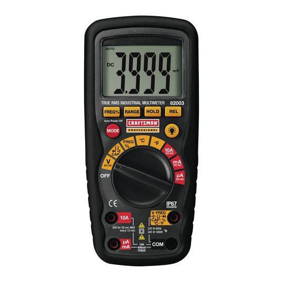
CONTROLS AND JACKS 1. 4,000 count LCD display 2. RANGE button 3. Hz and % button 4. Mode button 5. Function switch 6. mA, µA and 10A input jacks 7. COM input jack 8. Positive input jack 9. Backlight button 10. -
Page 7: Specifications
SPECIFICATIONS Function Range Resolution Accuracy (0.5% reading + 2 digits) DC Voltage 400mV 0.1mV 0.001V (1.2% reading + 2 digits) 0.01V 400V 0.1V (1.5% reading + 2 digits) 1000V (2.0% reading + 10 digits) AC Voltage 400mV 0.1mV 0.001V (2.0% reading + 5 digits) 0.01V 400V 0.1V... - Page 8 Supplied Probe range: -58.0 to 482 F (-50.0 to 250 Note: An optional probe that is rated to the full range of the meter is available from the www.craftsman.com website. Note: Accuracy is stated at 65 F to 83 F (18...
- Page 9 Enclosure Double molded, waterproof (IP67) Shock (Drop Test) 6.5 feet (2 meters) Diode Test Test current of 0.3mA typical, open circuit voltage 1.5V DC typical Continuity Check Audible signal will sound if the resistance is less than 100 (approx.), test current <0.3mA Temperature Sensor Requires type K thermocouple Input Impedance...
- Page 10 Safety This meter is intended for origin of installation use and protected, against the users, by double insulation per EN61010-1 and IEC61010-1 2 Edition (2001) to Category IV 600V and Category III 1000V; Pollution Degree 2. The meter also meets UL 61010-1, 2 Edition (2004), CAN/CSA C22.2 No.
-
Page 11: Battery Installation
BATTERY INSTALLATION WARNING: To avoid electric shock, disconnect the test leads from any source of voltage before removing the battery cover. 1. Turn power off and disconnect the test leads from the meter. 2. Open the rear battery cover by removing two screws (B) using a Phillips head screwdriver. -
Page 12: Operating Instructions
OPERATING INSTRUCTIONS WARNING: Risk of electrocution. High-voltage circuits, both AC and DC, are very dangerous and should be measured with great care. 1. ALWAYS turn the function switch to the OFF position when the meter is not in use. 2. If “OL” appears in the display during a measurement, the value exceeds the range you have selected. -
Page 13: Ac Voltage Measurements
AC VOLTAGE (Frequency, Duty Cycle) MEASUREMENTS AC VOLTAGE: The probe tips may not be long enough to contact the live parts inside some 240V outlets for appliances because the contacts are recessed deep in the outlets. As a result, the reading may show 0 volts when the outlet actually has voltage on it. -
Page 14: Dc Current Measurements
DC CURRENT MEASUREMENTS CAUTION: Do not make current measurements on the 20A scale for longer than 30 seconds. Exceeding 30 seconds may cause damage to the meter and/or the test leads. 1. Insert the black test lead banana plug into the negative COM jack. -
Page 15: Ac Current Measurements
AC CURRENT (Frequency, Duty Cycle) MEASUREMENTS CAUTION: Do not make current measurements on the 20A scale for longer than 30 seconds. Exceeding 30 seconds may cause damage to the meter and/or the test leads. 1. Insert the black test lead banana plug into the negative COM jack. -
Page 16: Resistance Measurements
RESISTANCE MEASUREMENTS WARNING: To avoid electric shock, disconnect power to the unit under test and discharge all capacitors before taking any resistance measurements. Remove the batteries and unplug the line cords. 1. Set the function switch to the ΩCAP position. 2. -
Page 17: Continuity Check
CONTINUITY CHECK WARNING: To avoid electric shock, never measure continuity on circuits or wires that have voltage on them. 1. Set the function switch to the Ω CAP position. 2. Insert the black lead banana plug into the negative COM jack. Insert the red test lead banana plug into the positive ... -
Page 18: Capacitance Measurements
CAPACITANCE MEASUREMENTS WARNING: To avoid electric shock, disconnect power to the unit under test and discharge all capacitors before taking any capacitance measurements. Remove the batteries and unplug the line cords. 1. Set the rotary function switch to the Ω CAP position. -
Page 19: Temperature Measurements
Note: The supplied thermocouple is rated for 482°F (250°C). For higher temperatures you can purchase a high temperature thermocouple from www.craftsman.com. FREQUENCY SENSITIVITY (ELECTRICAL) The frequency sensitivity is range dependent when the function is selected from while in the voltage or current measuring function. -
Page 20: Autoranging/Manual Range Selection
AUTORANGING/MANUAL RANGE SELECTION When the meter is first turned on, it automatically goes into Autoranging. This automatically selects the best range for the measurements being made and is generally the best mode for most measurements. For measurement situations requiring that a range be manually selected, perform the following: 1. -
Page 21: Auto Power Off
AUTO POWER OFF The auto off feature will turn the meter off after 30 minutes. To disable the auto power off feature, hold down the MODE button and turn the meter on. LOW BATTERY INDICATION icon will appear in the display when the battery voltage becomes low. -
Page 22: Maintenance
MAINTENANCE WARNING: To avoid electric shock, disconnect the test leads from any source of voltage before removing the back cover or the battery cover. WARNING: To avoid electric shock, do not operate your meter until the battery cover is in place and fastened securely. This multimeter is designed to provide years of dependable service, if the following care instructions are performed: 1. -
Page 23: Battery Replacement
BATTERY INSTALLATION WARNING: To avoid electric shock, disconnect the test leads from any source of voltage before removing the battery cover. 1. Turn power off and disconnect the test leads from the meter. 2. Open the rear battery cover by removing two screws (B) using a Phillips head screwdriver. -
Page 24: Fuse Replacement
5. Always use a fuse of the proper size and value (0.5A/1000V fast blow for the 400mA range [SIBA 70-172-40], 10A/1000V fast blow for the 20A range [SIBA 50-199-06]). 6. Replace and secure the rear cover, battery and battery cover. WARNING: To avoid electric shock, do not operate your meter until the fuse cover is in place and fastened securely. -
Page 25: Troubleshooting
If You Do Not Understand How the Meter Works: Call our Customer Service Line 1-888-326-1006. SERVICE AND PARTS Item Number Description 82378 Set of black and red Test Leads 82003-D Replacement battery cover 82003-C Front cover 82003-CS Rear cover screws 82377...