Table of Contents
Available languages
Available languages
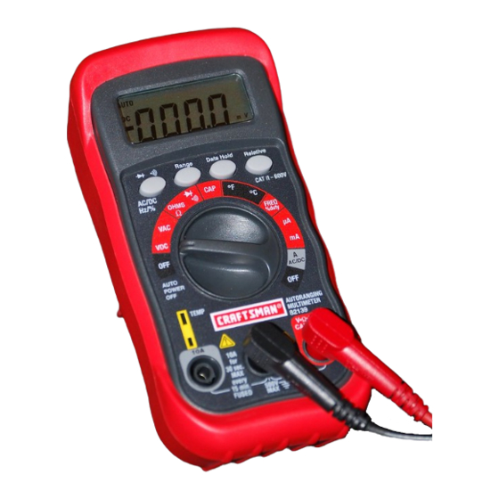
Owner's Manual
AutoRanging
Digital MultiMeter
Model No.
82139
I
QQ O 1!
G
CAUTION:
Read, understand and
follow Safety Rules and Operating
Instructions in this manual before
using this product.
• Safety
• Operation
• Maintenance
• EspaSoI
© Sears, Roebuck
and Co., Hoffman
Estates, IL 60179 U.S.A.
www.craftsman.com
070606
Chapters
Table of Contents

Related Manuals for Craftsman 82139


Summary of Contents for Craftsman 82139
- Page 1 Model No. 82139 • Safety CAUTION: Read, understand and • Operation follow Safety Rules and Operating Instructions in this manual before • Maintenance using this product. • EspaSoI © Sears, Roebuck and Co., Hoffman Estates, IL 60179 U.S.A. www.craftsman.com 070606...
-
Page 2: Table Of Contents
IP':_ :] II :[o] _l[o[o]_i / :1_i II Page Warranty Safety Instructions Safety Symbols Control and Jacks Symbols and Annunciators Specifications Battery Installation Operating Instructions AutoRanging/ManualRanging Data Hold Relative DC Voltage Measurements AC Voltage Measurements DC Current Measurements AC Current Measurements Resistance Measurements Continuity Check... -
Page 3: Warranty
D]_I:lk'd:1:1:1 ill I IlVlVl:l:] :;:1 _iI ONE YEAR FULL WARRANTY ON CRAFTSMAN MULTIMETER If this CRAFTSMAN Multimeter fails to give complete satisfaction within one year from the date of purchase, RETURN IT TO THE NEAREST SEARS STORE OR OTHER CRAFTSMAN... - Page 4 2. USE EXTREME CAUTION when working with high voltages. DO NOT measure voltage if the voltage on the "COM" input jack exceeds 500V above earth ground. NEVER connect the meter leads across a voltage source while the function switch is in the current, resistance, or diode mode. Doing so can damage the meter.
- Page 5 _To] _ i / _To]iF.']r_*l _ Ie]PF_*To_ 4000 count Liquid Crystal Display with symbolic signs Function switch Positive input jack ./,8 COM (negative) input jack 10A (positive) input jack for 10A DC or AC measurements Continuity/Diode, Frequency/Duty Cycle or AC/DC selection button.
- Page 6 ,t".,1 _ [l! IiI [___1t [.] _B Function Resolution Range Accuracy 400mY 0.1mV DC Voltage _+(0.5% reading + 2 digits) (V DC) _+(1.0% reading + 2 digits) 10mV 400V 100mV 600V _+(1.5% reading + 2 digits) 400mY 0.1mV AC Voltage _+(2.0% reading + 30 digits) (V AC) _+(1.5% reading + 3 digits...
-
Page 7: Specifications
Resolution Function Range Accuracy Capacitance _+(5.0% reading +10digits) 40nF 10pF _+(5.0% reading +7digits) 400nF 0.1nF _+(3.5% reading +5digits) 4IJF 10nF 40,uF 200,uF 0.1!iF _+(5.0% reading +5digits) 0.1% Duty C ycle0.1-99.9% _+(1.2% reading +2digits) Pulse width: 100!_s -100ms 0.001Hz Frequency 9.999Hz _+(1.5% reading +5digits) 99.99Hz... - Page 8 Diode Test Test current of 0.3mA maximum, open circuit voltage 1.5V DC typical Continuity Check Audible signal will sound if the resistance is less than approximately 30£-._, test current <0.7mA Temperature sensor Requires type K thermocouple Input Impedance 7.5M£-2(VDC and VAC) 4000 count LCD Display Overrange indication...
- Page 9 I WARNING: Toavoid e lectric shock, disconnect the test l eads from any source ofvoltage before removing the battery door. 1. Disconnect the test l eads from the meter. 2. Remove the protective rubber boot (ifinstalled).---_-_ 3. Open the battery door b y loosening the screw u sing a Phillips head s crewdriver.
-
Page 10: Autoraging/Manual Ranging Selection
ARNING: Risk of electrocution. High-voltage circuits, both AC and DC, are very dangerous and should be measured with great care. 1. ALWAYS turn the function switch to the OFF position when the meter is not in use. This meter has Auto OFF that automatically shuts the meter OFF if 15 minutes elapse between uses. -
Page 11: Relative
RELATIVE The relative measurement feature allows you to make measurements relative to a stored reference value. A reference voltage, current, etc. can be stored and measurements made in comparison to that value. The displayed value is the difference between the reference value and the measured value. -
Page 12: Ac Voltage Measurements
AC VOLTAGE MEASUREMENTS WARNING: Risk of Electrocution. The probe tips may not be long enough to contact the live parts inside some 240V outlets for appliances because the contacts are recessed deep in the outlets. As a result, the reading may show 0 volts when the outlet actually has voltage on it. -
Page 13: Ac Current Measurements
6. Remove power from the circuit under test, then open u pthe circuit at the point where you wish tomeasure current. 7. Touch the black t est p robe t iptothe negative side ofthe circuit. Touch the red test p robe tiptothe positive side ofthe circuit. 8. -
Page 14: Resistance Measurements
RESISTANCE MEASUREMENTS under test and discharge all capacitors before taking any resistance ARNING: TO avoid electric shock, disconnect power to the unit measurements. Remove the batteries and unplug the line cords. 1. Set the function switch to the £-2position. Insert the black test lead banana plug into the negative (COM) jack and the red test lead banana plug into the positive £-2 jack. -
Page 15: Diode Test
DIODE TEST ARNING: To avoid electric shock, do not test any diode that has voltage on it. 1. Set the function switch to-_-))_)position. Press the -)1--))_) button until the _ symbol appears in the display. Insert the black test lead banana plug into the negative (-) jack (COM) and the red test lead banana plug into the positive (+) jack (_-.)). -
Page 16: Capacitance Measurements
CAPACITANCE MEASUREMENTS under test and discharge all capacitors before taking any capacitance ARNING: To avoid electric shock, disconnect power to the unit measurements. Remove the batteries and unplug the line cords. 1. Set the function switch to the CAP position. ("nF" and a small value will appear in the display). - Page 17 source of voltage before removing the back cover or the battery or fuse I WARNING: To avoid electric shock, disconnect the test leads from any doors. I WARNING: To avoid electric shock, do not operate your meter until the battery and fuse doors are in place and fastened securely, This MultiMeter is designed to provide years of dependable service, if the following care instructions...
- Page 18 I WARNING: To avoid e lectric shock, donot o perate your meter until the battery door i sinplace a nd fastened securely. REPLACING THE FUSES WARNING: To avoid e lectric shock, disconnect the test l eads from any source of voltage before removing the fuse door. 1.
- Page 19 / ;(ellJ :] II :[_ -" [ele]l i I_[€ There may be times when your meter does not operate properly. Here are some common problems that you may have and some easy solutions to them. Meter Does Not Operate: 1. Always read all the instructions in this manual before use.
- Page 20 • Seguridad PRECAUCION: Lea, comprenda y siga las Reglas de Seguridad e • Operaci6n Instrucciones de operaci6n en este • Mantenimiento manual antes de operar este • Espa_oI producto (c) Sears, Roebuck and Co., Hoffman Estates, IL 60179 U.S.A. www.sears.com/craftsman 070606...
- Page 21 f__:! ur__! J ]:l[o,Zo] _i II :1_IIJIe Pagina Garantia Instrucciones de seguridad Sefiales de seguridad Control y conexiones Sefiales y anunciadores Especificaciones Instalaci6n de la bateria Instrucciones de operaci6n Escala automatica/Escala manual Retenci6n de datos Relativo Medici6n de voltaje CD Medici6n de voltaje CA Medici6n de corriente CD Medici6n de corriente CA...
- Page 22 Regrese el producto al cualquizer tienda de Sears o cualquier tienda de Craftsman para su reemplazo. Si este producto es usado comercialmente o para renta, esta garantia se aplica s61o durante los primeros 90 dias despues de la fecha de compra.
-
Page 23
1. NUNCA aplique al medidor voltaje o corriente que exceda m&ximos especificados: EXTREME SUS PRECAUClONES al trabajar con alto voltaje. NO mida voltaje si el voltaje en el enchufe de entrada <
> e xcede 500V sobre tierra fisica. NUNCA conecte los alambres del medidor a una fuente de voltaje cuando el conmutador... - Page 24 u_o] _ i / _To]I ::F.'l'ioTo] _I _14[o]_I::F: Pantalla de cristal liquido de 4000 cuentas con seSales simb61icas 2. Conmutador de funci6n Enchufe positivo de alimentaci6n. Enchufe (negativo) de alimentaci6n Enchufe de alimentaci6n de 10A (positivo) para mediciones de 10A CD o CA 6.
- Page 25 _",)",,,1 =[_]I_1 [_I':T_][e)_I =[,,,",) Funci6n Escala Resoluci6n Precisi6n 400mV 0.1mV ±(0.5%lectura + 2 digitos) Voltaje CD (V CD) ±(1.0%lectura + 2 digitos) 10 mV 400V 100mV 600V ±(1.5%lectura + 2 digitos) 400mV 0.1mV ±(2.0% lectura + 30 digitos) Voltaje CA (V CA) ±(1.5%lectura + 3 digitos...
-
Page 26: Especificaciones
_",)",,,1 =[_]I_1 [_I':__][e)_I =[_ FunciSn Escala Resoluci6n Precisi6n Capacitancia ±(5.0%lectura + 10 digitos) 40nF 10pF ±(5.0%lectura + 7 digitos) 400nF 0.1nF ±(3.5%lectura + 5 digitos) 4!iF 10nF 40HF 0.1!iF ±(5.0%lectura + 5 digitos) 200!iF 0.1% ±(1.2%lectura + 2 digitos) R@gimen de 0.1-99.9% trabajo Ancho de impulso: 100!_s - 100ms... -
Page 27
Impedancia de alimentaci6n 7.5M_-._ (VCD y VCA) Pantalla 4000 cuentas LCD Indicaci6n de fuera de escala <
- > indicado Polaridad Automatico (no hay indicaci6n para polaridad positiva); Signo de menos (-) para polaridad negativa. Tasa de medici6n 2 veces por segundo, nominal Apagado autom&tico El medidor se apaga automaticamente despues de 15 minutos de inactividad...
- Page 28 I I_ [_'-]1 ir_*1 IF_*T_] [e] _II e) :ll Ir_*ll :]r-*11 / :1 ;,,1 r:l de prueba de cualquier fuente de voltaje antes de abrir la tapa de la bateria. Desconecte los hilos de prueba del medidor. 2. Quite la funda de goma (siesta colocada). 3.
- Page 29 O" Riesgo voltaje, tanto CD y CA, son muy peligrosos y deberan ser medidos con gran I ADVERTENClA: de electrocuci6n. Los circuitos de alto cuidado. 1. SIEMPRE gire el conmutador de funci6n a la posici6n OFF cuando el medidor no este en uso. Este medidor tiene Auto OFF, que automaticamente apaga el medidor si transcurren mas de 15 minutos...
-
Page 30: Retenci6N De Datos
RETENCION DE DATOS La funci6n de retenci6n de datos permite al medidor <_congelar_ una medida para referencia posterior. Presione el bot6n DATA HOLD para <_congelar_ la lectura en el indicador. En la pantalla aparecera el indicador <_HOLD_. Presione el bot6n DATA HOLD para regresar a operaci6n normal. RELATIVO La funci6n RELATIVO le permite tomar medidas relativas a un valor de... -
Page 31: Medici6N De Voltaje Cd
punto decimal yvalor apropiado. Si s einvierte lapolaridad, lapantalla indicara (-)menos antes del v alor. MEDIClON DE VOLTAJE ADVERTENClA: Riesgo deelectrocuci6n. Las puntas delas sondas pueden noser I osuficientemente largas para h acer contacto con partes vivas d entro dealgunos tomas decorriente de240V para aparatos debido aque los contactos... - Page 32 3. Para m ediciones decorriente dehasta 400mA CD, fije elconmutador defunci6n enlaposici6n delaescala mA einserte el conector banana rojo enelenchufe (mA). 4. Para m ediciones decorriente dehastal0A CD, fijeel conmutador de funci6n enlaposici6n Aeinserte el conector banana del h ilo deprueba rojo enelenchufe 10A.
-
Page 33: Medici6N De Resistencia
4. Para m ediciones decorriente dehastal0A CA, fije elconmutador funci6n enlaposici6n Aeinserte elconector banana del h ilo de prueba rojo enelenchufe 10A. 5. Presione elbot6n CA/CD hasta que aparezca <>. 6. Corte l aenergia del circuito bajo prueba, enseguida abra e lcircuito en elpunto donde desea m edir lacorriente. -
Page 34: Prueba De Continuidad
PRUEBA DE CONTINUIDAD I ADVERTENCIA: Para evitar choque electrico, nunca mida continuidad en circuitos o alambres que tengan voltaje en ellos. Fije el conmutador de funci6n en la posici6n -_o))). Inserte el conector banana negro en el enchufe negativo (-) (COM) y el conector banana del hilo de prueba rojo en el enchufe positivo (+) (£-._). -
Page 35: Medici6N De Capacitancia
NOTA: El v alor indicado enlapantalla durante laprueba dediodo e sel voltaje directo. MEDIClON DE FRECUENClA O FACTOR DE TRABAJO 1. Fije el conmutador de funci6n en la posici6n FREQ. Inserte el conector banana negro en el enchufe negativo (-) (COM) y el conector banana del hilo de prueba rojo en el enchufe positivo (+) (F). - Page 36 MEDICIONES DE TEMPERATURA sondas de prueba de cualesquier fuente de voltaje antes de tomar I ADVERTENCIA: Para evitar choque electrico, desconecte ambas mediciones de temperatura. 1. Si desea tomar mediciones de temperatura en °F, fije el conmutador de funciSn en la escala °F. Si desea tomar mediciones de temperatura en °C, fije el conmutador...
- Page 37 ADVERTENClA: Para evitar choque electrico, desconecte los alambres de prueba de cualquier fuente de voltaje antes de quitar la cubierta posterior o la tapa de la bateria o fusible. ADVERTENClA: Para evitar choque electrico, no opere su medidor hasta que las tapas de la bateria y fusibles esten aseguradas en su lugar.
-
Page 38: Reemplazo De Baterias
REEMPLAZO DE LAS BATERiAS ara ev, ar oho ue e,eotr,oo, desooneote,os a,am res de prueba de cualquier fuente de voltaje antes de abrir la tapa de la bateria. Cuando se consuma la carga de las baterias o caiga debajo del voltaje de operaci6n, en la pantalla LCD aparecer_l el indicador <>... - Page 39 INSCRITO EN UL La marca UL no indica que la precisiSn de las lecturas de este producto han sido evaluadas. •_o] m Lu[o] [o]_II m] : 11 :,K{o] : ] ml :l,v_ r.*T_ Puede haber ocasiones en que su medidor no funcione correctamente. Estos son algunos problemas comunes que puede tener y algunas soluciones faciles para ellos.
- Page 40 NQmero dearticulo Descripci6n 82374 Kit d el f usible 93891 Bateria AAA (requiere 82378 Juego dehilos d eprueba rojo ynegro 82139-DB Tapa d eremplazo del c ompartimento debateria 82139-DF Reemplazo delatapa de fusibles 82139-CS Tornillos delacubierta posterior 82377 Sonda termopar Para p iezas dereemplazo embarcadas directamente...