Dell 5230dn Mono Laser Printer Service Manual
Service manual
Hide thumbs
Also See for 5230dn Mono Laser Printer:
- Quick reference manual (2 pages) ,
- Specifications (4 pages) ,
- User manual (193 pages)
Table of Contents
Quick Links
Table of Contents

Related Manuals for Dell 5230dn Mono Laser Printer


Summary of Contents for Dell 5230dn Mono Laser Printer
- Page 1 15 December 2009...
- Page 2 ! ! ! ...
-
Page 3: Table Of Contents
Table of contents Table of contents ............iii Notices and safety information . - Page 4 Sensor (pass through) lingering jam service check........2-140 Sensor (pass through) static jam service check .
- Page 5 INPUT TRAY TESTS ............. 3-14 Feed Tests (input tray) .
- Page 6 Wiper Messages ..............3-28 Clear Custom Status .
- Page 7 Display Log ..............3-47 Print Log .
- Page 8 Polygon printhead assembly ............3-69 Oscillating printhead assembly .
- Page 9 Wear strips ..............3-91 Media tray assembly .
- Page 10 Duplex assembly removal (5350dn, 5530dn, and T656) ....... .4-16 Duplex cooling fan removal (5350dn, 5530dn, and T656) .......4-17 Duplex drive motor assembly removal (5350dn, 5530dn, and T656) .
- Page 11 Transfer roll assembly removal ........... 4-80 Transfer roll bracket assembly, left removal .
- Page 12 High capacity stacker right frame removal .........4-142 High capacity stacker left frame removal .
- Page 13 Connections ............... . 5-1 Preventive maintenance .
- Page 14 Service Manual...
-
Page 15: Notices And Safety Information
Notices and safety information The following laser notice labels may be affixed to this printer. Laser notice The printer is certified in the U.S. to conform to the requirements of DHHS 21 CFR Subchapter J for Class I (1) laser products, and elsewhere is certified as a Class I laser product conforming to the requirements of IEC 60825-1. - Page 16 Avisos sobre el láser Se certifica que, en los EE.UU., esta impresora cumple los requisitos para los productos láser de Clase I (1) establecidos en el subcapítulo J de la norma CFR 21 del DHHS (Departamento de Sanidad y Servicios) y, en los demás países, reúne todas las condiciones expuestas en la norma IEC 60825-1 para productos láser de Clase I (1).
- Page 17 Laserilmoitus Tämä tulostin on sertifioitu Yhdysvalloissa DHHS 21 CFR Subchapter J -standardin mukaiseksi luokan I (1) - lasertuotteeksi ja muualla IEC 60825-1 -standardin mukaiseksi luokan I lasertuotteeksi. Luokan I lasertuotteita ei pidetä haitallisina. Tulostimen sisällä on luokan IIIb (3b) laser, joka on nimellisteholtaan 5 mW:n galliumarsenidilaser ja toimii 770 - 795 nanometrin aallonpituuksilla.
- Page 18 Avís sobre el Làser Segons ha estat certificat als Estats Units, aquesta impressora compleix els requisits de DHHS 21 CFR, apartat J, pels productes làser de classe I (1), i segons ha estat certificat en altres llocs, és un producte làser de classe I que compleix els requisits d’IEC 60825-1.
- Page 19 Notices and safety information...
- Page 20 Service Manual...
-
Page 21: Lithium Warning
Lithium warning CAUTION This product contains a lithium battery. THERE IS A RISK OF EXPLOSION IF THE BATTERY IS REPLACED BY AN INCORRECT TYPE. Discard used batteries according to the battery manufacturer’s instructions and local regulations. Safety information • The safety of this product is based on testing and approvals of the original design and specific components. - Page 22 Sicherheitshinweise • Die Sicherheit dieses Produkts basiert auf Tests und Zulassungen des ursprünglichen Modells und bestimmter Bauteile. Bei Verwendung nicht genehmigter Ersatzteile wird vom Hersteller keine Verantwortung oder Haftung für die Sicherheit übernommen. • Die Wartungsinformationen für dieses Produkt sind ausschließlich für die Verwendung durch einen Wartungsfachmann bestimmt.
- Page 23 Informació de Seguretat • La seguretat d'aquest producte es basa en l'avaluació i aprovació del disseny original i els components específics. El fabricant no es fa responsable de les qüestions de seguretat si s'utilitzen peces de recanvi no autoritzades. • La informació...
-
Page 24: Preface
Preface This manual contains maintenance procedures for service personnel. It is divided into the following chapters: General information contains a general description of the printer and the maintenance approach used to repair it. Special tools and test equipment, as well as general environmental and safety instructions, are discussed. -
Page 25: General Information
1. General information The Dell laser printers are letter-quality page printers designed to attach to personal computers and to most computer networks. The Dell laser printers are available in the following models: Configuration Machine type MFG Model / Dell Model... -
Page 26: Options
Options Available internal options • Memory cards — Printer memory — Flash memory — Fonts • Firmware cards — Bar Code and Forms — IPDS and SCS/TNe — PrintCryption — PRESCRIBE • Printer hard disk • LXK Internal Solutions Ports (ISP) —... -
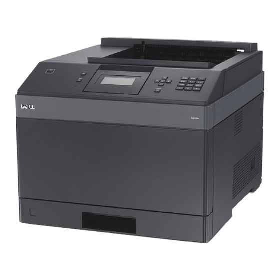
Page 27: Printer Configurations
Printer configurations Basic model The following illustration shows the basic printer model. Feature Paper Capacity Standard exit bin 250- or 550-sheet Printer control panel Multipurpose feeder 100 sheets Standard tray (Tray 1) 250- or 550-sheets Based on 75 g/m (20 lb.) paper. General information... -
Page 28: Fully Configured Model
You must use either a printer stand or printer base if you are using a 2000-sheet tray, a duplex unit, and an input option, or more than one input option. More information is available on our Dell Web site at www.dell.com. Service Manual... - Page 29 2000-sheet drawer. Certain other configurations also must have a printer stand or printer base. More information is available on our Dell Web site at www.dell.com. General information...
-
Page 30: Supported Paper Sizes, Types, And Weights
Supported paper sizes, types, and weights The following tables provide information on standard and optional paper sources and the types of paper they support. Note: For an unlisted paper size, select the closest larger listed size. Paper sizes supported by the printer 250-or 550-sheet Optional Multipurpose... -
Page 31: Paper Types And Weights Supported By The Printer
250-or 550-sheet Optional Multipurpose Paper size Dimensions trays (standard 2000-sheet Duplex unit feeder or optional tray Other Envelope 98 x 162 mm (3.9 x 6.4 in.) to 176 x 250 mm (6.9 x 9.8 in.) This size appears in the Paper Size menu only when the paper source does not support size sensing or when size sensing is turned off. -
Page 32: Tools Required
The finisher supports 60-176 g/m2 (16-47 lb) paper weights. Optional hardware Output Expander (550 Standard exit bin StapleSmart II Paper type sheets) or High 5-Bin Mailbox (350 or 550 sheets) Finisher Capacity (500 sheets) (500 sheets) Output stacker (1850 sheets) Paper •... -
Page 33: Acronyms
Acronyms BLDC Brushless DC motor Customer Replaceable Unit Customer setup DIMM Dual Inline Memory Module DRAM Dynamic Random Access Memory Digital multimeter Enhanced Data Out EEPROM Electrically Erasable Programable Read-Only Memory Electrophotographic process EPROM Erasable Programmable Read-Only Memory Electrostatic Discharge Field Replaceable Unit Gigabyte HCIT... - Page 34 1-10 Service Manual...
-
Page 35: Diagnostic Information
2. Diagnostic information Start CAUTION: Unplug the power cord from the electrical outlet before you connect or disconnect any cable electronic board or assembly. CAUTION: If the printer is kept on, never touch the conductive parts if not specifically required. The power switch and inlet of the low voltage power supply card (LVPS card) assembly is live even while the power supply is cut off. -
Page 36: Confirm The Installation Status
The following is an example of the events that occur during the POR sequence: 1. Turn the machine on. 2. The Dell splash screen appears with a progress bar in the center until the code is loaded. 3. The fuser cooling fan turns on. -
Page 37: User Attendance Messages
User attendance messages Error code or Error contents Description/Action Possible repair actions message System System Timeout The system detects a firmware Turn the power off; wait a few Timeout component that is no longer seconds, and then turn the responding. power back on. - Page 38 Error code or Error contents Description/Action Possible repair actions message Res Save Off This IR is displayed when the This message displays when Deficient Memory printer lacks sufficient memory the printer lacks sufficient to enable Resource Save. This memory to enable Resource message usually indicates the Save.
- Page 39 Error code or Error contents Description/Action Possible repair actions message Insufficient Memory This message displays when The following actions may be the printer memory used to taken: restore the Print and Hold jobs from the disk and found that • Press to clear the some or all of the jobs could message.
- Page 40 Error code or Error contents Description/Action Possible repair actions message 44.01 RFID Error Bad tag error: a tag has failed 1. Retest using new RFID to program, or the “Retry media. Count” has been exceeded. 2. Check the RFID firmware card, RFID interface card, Note: This error is not a data RFID cable, and RFID...
- Page 41 Error code or Error contents Description/Action Possible repair actions message 44.26 RFID Error Based on tag location 1. These error codes most parameters: tag is not likely indicate a problem compatible with printer with the customer’s datastream, and not the 44.27 RFID Error Unsupported SA Code...
- Page 42 Error code or Error contents Description/Action Possible repair actions message 44.36 RFID Error Invalid X/Y Position 1. This error code most likely indicates a problem with the customer’s datastream, and not the RFID Option itself. Ensure there is nothing wrong with the customer’s datastream.
- Page 43 Error code or Error contents Description/Action Possible repair actions message Flash Full This message displays when Press to clear the the printer detects an message. The flash is marked unformatted flash at power on. as bad and normal operation continues. Flash operations are not allowed until the flash is formatted.
- Page 44 Error code or Error contents Description/Action Possible repair actions message Serial Port [x] This error displays when data Go to network service check. Disabled is sent to the printer across an “Network service check” serial port, but the port has on page 2-170.
- Page 45 Error code or Error contents Description/Action Possible repair actions message Too Many Disks This error code displays when 1. Turn off and unplug the Installed too many disks are attached to printer. the printer. 2. Remove the excess disks. 3. Plug in the printer, and turn it on.
- Page 46 Error code or Error contents Description/Action Possible repair actions message Incompatible Output An incompatible output bin is 1. Turn off and unplug the Bin [x] installed. For Output Bin x, x=1, printer. 2, or 3. 2. Remove the incompatible output option. Remove the incompatible 3.
- Page 47 Error code or Error contents Description/Action Possible repair actions message Cartridge Low This IR is displayed when Replace the print cartridge. cartridge low occurs and the cartridge low alarm is activated. If cartridge alarm is not activated, this is not an intervention condition.
-
Page 48: Error Code Table 1
Error code table Error code or Error contents Description/Action Possible repair actions message 200.00 Sensor (input) area The media is jammed in the 1. Fan the media and check for sensor (input) area. obstructions. 2. Go to sensor (input) service check. - Page 49 Error code or Error contents Description/Action Possible repair actions message 200.09 Printhead laser start The printhead laser start 1. Check all connections on failure process failed because it did the printhead. not receive proper feedback 2. Check all connections on signal from the printhead the main drive motor motor.
- Page 50 Error code or Error contents Description/Action Possible repair actions message 200.13 Sensor (input) static Media remains on the sensor Go to sensor (input) static jam (input) during the warm up service check. sequence. “Sensor (input) static jam service check” on page 2-129.
- Page 51 Error code or Error contents Description/Action Possible repair actions message 200.27 Sensor (input) The media reached the sensor Go to sensor (input) lingering lingering jam (input) but did not clear it within jam service check. the specified time. “Sensor (input) lingering Source = Tray 2 Tray level = Not Low jam service check.”...
- Page 52 Error code or Error contents Description/Action Possible repair actions message 200.39 Sensor (input) The media reached the sensor Go to sensor (input) lingering lingering jam (input) but did not clear it within jam service check. the specified time. “Sensor (input) lingering Source = Tray 3 Tray level = Empty jam service check.”...
- Page 53 Error code or Error contents Description/Action Possible repair actions message 201.02 Sensor (fuser output) The media is late reaching the Go to sensor (fuser output) late late jam. sensor (fuser output) within the jam service check. specified time. “Sensor (fuser output) Type 1 fuser late jam service check.”...
- Page 54 Error code or Error contents Description/Action Possible repair actions message 201.27 Sensor (fuser output) The media is late reaching the Go to sensor (fuser output) late late jam. sensor (fuser output) within the jam service check. specified time. “Sensor (fuser output) Type 2 fuser late jam service check.”...
- Page 55 Error code or Error contents Description/Action Possible repair actions message 201.51 Main drive motor The main drive motor assembly 1. Check all connections on assembly load error. has failed or caused high the main drive motor mechanical load due to paper assembly.
- Page 56 Error code or Error contents Description/Action Possible repair actions message 201.57 Sensor (fuser output) The media is late reaching the Go to sensor (fuser output) late late jam sensor (fuser output) within the jam service check. specified time. “Sensor (fuser output) Type 1 fuser late jam service check.”...
- Page 57 Error code or Error contents Description/Action Possible repair actions message 201.80 Operator panel door The printer detected that the 1. Remove all media present assembly interlock switch (operator panel door in media path. switch open failure interlock) did not cycle prior to 2.
- Page 58 Error code or Error contents Description/Action Possible repair actions message 202.04 Sensor (fuser output) The sensor (fuser output) Go to sensor (fuser output) bounce rebounded once the trailing service check. edge of the media passed. “Sensor (fuser output) Type 1 fuser service check”...
- Page 59 Error code or Error contents Description/Action Possible repair actions message 202.25 Paper jam around Page may be jammed in fuser 1. Remove all media present fuser exit or redrive exit or redrive area. in media path. area. 2. Check media for proper installation.
- Page 60 Error code or Error contents Description/Action Possible repair actions message 202.34 Sensor (fuser output) Media reached the sensor Go to sensor (fuser output) lingering jam. (fuser output) but did not clear lingering jam service check. it in the specified time. “Sensor (fuser output) Type 2 fuser lingering jam service check.”...
- Page 61 Error code or Error contents Description/Action Possible repair actions message 202.51 Sensor (fuser output) Media reached the sensor Go to sensor (fuser output) lingering jam. (fuser output) but did not clear lingering jam service check. it in the specified time. “Sensor (fuser output) Destination is standard bin.
- Page 62 Error code or Error contents Description/Action Possible repair actions message 202.61 Sensor (fuser output) Media reached the sensor Go to sensor (fuser output) lingering jam. (fuser output) but did not clear lingering jam service check. it in the specified time. “Sensor (fuser output) Destination is standard bin.
- Page 63 Error code or Error contents Description/Action Possible repair actions message 202.78 Sensor (narrow Media remains on the sensor 1. Go to sensor (fuser output) media) static jam (narrow media) during the static jam service check. warm up sequence. “Sensor (fuser Type 2 fuser output) static jam service check”...
- Page 64 Error code or Error contents Description/Action Possible repair actions message 202.87 Sensor (fuser output) Media reached the sensor Go to sensor (fuser output) lingering jam. (fuser output) but did not clear lingering jam service check. it in the specified time. “Sensor (fuser output) Destination is output option.
- Page 65 Error code or Error contents Description/Action Possible repair actions message 203.08 Redrive motor load The redrive motor assembly 1. Remove all media present error has failed or caused high in media path. mechanical load during the 2. Ensure that upper redive warm up sequence.
- Page 66 Error code or Error contents Description/Action Possible repair actions message 230.00 Paper jam around Page may be jammed in 1. Remove all media present internal duplex. internal duplex area. in media path. 2. Check for obstructions in Source = Internal media path.
- Page 67 Error code or Error contents Description/Action Possible repair actions message 230.08 Internal duplex drive The internal duplex drive motor 1. Remove all media present motor load error assembly has failed or caused in media path. high mechanical load during 2. Check all connections on Source = Internal warm up sequence.
- Page 68 Error code or Error contents Description/Action Possible repair actions message 230.18 Internal duplex drive The internal duplex drive motor 1. Remove all media present motor assembly does not rotate at the specified in media path. underspeed error. speed. 2. Check all connections on the duplex media entrance Source = Internal drive motor assembly.
-
Page 69: Service Checks
Error code or Error contents Description/Action Possible repair actions message 234.00 Sensor (duplex exit) Media is late reaching the 1. Remove all media present late jam sensor (duplex exit) within the in media path. specified time. 2. Check media for proper Source = External installation. - Page 70 Error code or Error contents Description/Action Possible repair actions message 237.07 Paper jam around Page may be jammed in 1. Remove all media present external duplex external duplex area. in media path. 2. Check media for proper Source = External installation.
- Page 71 Error code or Error contents Description/Action Possible repair actions message 238.04 Sensor (duplex Media remains on the sensor 1. Remove all media present double-feed) static (duplex double-feed) during the in media path. warm up sequence. 2. Replace the external duplex assembly if problem Source = External remains.
- Page 72 Error code or Error contents Description/Action Possible repair actions message 239.01 External duplex Mechanical feed error or timing 1. Remove all media present assembly error error. in media path. 2. Check media for proper Source = External installation. duplex 3. Check for obstructions in media path.
- Page 73 Error code or Error contents Description/Action Possible repair actions message 239.04 Input device ready Mechanical feed error or timing 1. Remove all media present response error. error. in media path. 2. Check media for proper Source = External installation. duplex 3.
- Page 74 Error code or Error contents Description/Action Possible repair actions message 239.07 Select output device Mechanical feed error or timing 1. Remove all media present error. error. in media path. 2. Check media for proper Source = External installation. duplex 3. Check for obstructions in media path.
- Page 75 Error code or Error contents Description/Action Possible repair actions message 241.01 Pick motor control The pick motor does not reach 1. Remove all media present failure. the proper operating speed at in media path. the specified time. 2. Ensure media tray is not Media tray 1 overfilled.
- Page 76 Error code or Error contents Description/Action Possible repair actions message 241.08 Pick motor load error The pick motor has failed or 1. Remove all media present caused high mechanical load in media path. Source = Media tray 1 due to paper jam or bind. 2.
- Page 77 Error code or Error contents Description/Action Possible repair actions message 241.18 Sensor (input) late The media is late reaching the Go to sensor (input) late jam sensor (input) within the service check. specified time. “Sensor (input) late jam Source = Tray 1 service check.”...
- Page 78 Error code or Error contents Description/Action Possible repair actions message 242.05 Sensor (pass through) The media is late reaching the Go to sensor (pass through) late jam sensor (pass through) within late jam service check. the specified time. “Sensor (pass through) Source = Tray 2 late jam service check”...
- Page 79 Error code or Error contents Description/Action Possible repair actions message 242.52 Tray 2 pick motor The Pick motor encoder 1. Check all connections on overrun failure continues to detect pulses after the pick arm assembly. the motor was turned off. 2.
- Page 80 Error code or Error contents Description/Action Possible repair actions message 242.49 HCIT tray lift motor The HCIT tray lift motor has 1. Ensure the HCIT media tray stalled failure stalled or has become assembly is properly inserted obstructed. into the machine. Source = Tray 2 2.
- Page 81 Error code or Error contents Description/Action Possible repair actions message 242.65 Pick motor load error The pick motor has failed or 1. Remove all media present caused high mechanical load in media path. Source = Media tray 2 due to paper jam or bind. 2.
- Page 82 Error code or Error contents Description/Action Possible repair actions message 242.67 Pick motor overspeed The pick motor does not rotate 1. Remove all media present failure at the specified speed. in media path. 2. Ensure media tray is not Source = Media tray 2 overfilled.
- Page 83 Error code or Error contents Description/Action Possible repair actions message 243.00 Media tray 3 area jam The media is jammed in the 1. Remove all media present media tray 3 area. in media path. 2. Check media for proper installation. 3.
- Page 84 Error code or Error contents Description/Action Possible repair actions message 243.17 Media tray pulled jam A media tray above the source 1. Remove all media present tray was pulled during the in media path. Source = Tray 3 printing process. 2.
- Page 85 Error code or Error contents Description/Action Possible repair actions message 243.49 HCIT tray lift motor The HCIT tray lift motor has 1. Ensure the HCIT media tray stalled failure stalled or has become assembly is properly inserted obstructed. into the machine. Source = Tray 3 2.
- Page 86 Error code or Error contents Description/Action Possible repair actions message 243.65 Pick motor load error The pick motor has failed or 1. Remove all media present caused high mechanical load in media path. Source = Media tray 3 due to paper jam or bind. 2.
- Page 87 Error code or Error contents Description/Action Possible repair actions message 243.67 Pick motor overspeed The pick motor does not rotate 1. Remove all media present failure at the specified speed. in media path. 2. Ensure media tray is not Source = Media tray 3 overfilled.
- Page 88 Error code or Error contents Description/Action Possible repair actions message 244.00 Media tray 4 area jam The media is jammed in the 1. Remove all media present media tray 4 area. in media path. 2. Check media for proper installation. 3.
- Page 89 Error code or Error contents Description/Action Possible repair actions message 244.17 Media tray pulled jam A media tray above the source 1. Remove all media present tray was pulled during the in media path. printing process. 2. Close all media trays. 244.18 Pick retry timeout The engine timed out waiting...
- Page 90 Error code or Error contents Description/Action Possible repair actions message 244.49 HCIT tray lift motor The HCIT tray lift motor has 1. Ensure the HCIT media tray stalled failure stalled or has become assembly is properly inserted obstructed. into the machine. Source = Tray 4 2.
- Page 91 Error code or Error contents Description/Action Possible repair actions message 244.65 Pick motor load error The pick motor has failed or 1. Remove all media present caused high mechanical load in media path. Source = Media tray 4 due to paper jam or bind. 2.
- Page 92 Error code or Error contents Description/Action Possible repair actions message 244.67 Pick motor overspeed The pick motor does not rotate 1. Remove all media present failure at the specified speed. in media path. 2. Ensure media tray is not Source = Media tray 4 overfilled.
- Page 93 Error code or Error contents Description/Action Possible repair actions message 245.00 Media tray 5 area jam The media is jammed in the 1. Remove all media present media tray 5 area. in media path. 2. Check media for proper installation. 3.
- Page 94 Error code or Error contents Description/Action Possible repair actions message 245.17 Media tray pulled jam A media tray above the source 1. Remove all media present tray was pulled during the in media path. Source = Tray 5 printing process. 2.
- Page 95 Error code or Error contents Description/Action Possible repair actions message 245.49 HCIT tray lift motor The HCIT tray lift motor has 1. Ensure the HCIT media tray stalled failure stalled or has become assembly is properly inserted obstructed. into the machine. Source = Tray 5 2.
- Page 96 Error code or Error contents Description/Action Possible repair actions message 245.65 Pick motor load error The pick motor has failed or 1. Remove all media present caused high mechanical load in media path. Source = Media tray 5 due to paper jam or bind. 2.
- Page 97 Error code or Error contents Description/Action Possible repair actions message 245.67 Pick motor overspeed The pick motor does not rotate 1. Remove all media present failure at the specified speed. in media path. 2. Ensure media tray is not Source = Media tray 5 overfilled.
- Page 98 Error code or Error contents Description/Action Possible repair actions message 250.00 MPF area jam The media is jammed in the Go to sensor (input) service MPF area. check. Source = MPF “Sensor (input) service check” on page 2-120. 250.03 Sensor (input) late The media is late reaching the Go to sensor (input) late jam sensor (input) within the...
- Page 99 Error code or Error contents Description/Action Possible repair actions message 260.01 Envelope feeder Mechanical feed error or timing 1. Remove the envelope assembly error error. feeder. 2. Remove all media present in media path. 3. Check media for proper installation. 4.
- Page 100 Error code or Error contents Description/Action Possible repair actions message 260.06 Sensor (envelope The media is late reaching the 1. Remove the envelope feeder pass through) sensor (envelope feeder pass feeder. late jam through) within the specified 2. Remove all media present time.
- Page 101 Error code or Error contents Description/Action Possible repair actions message 260.15 Sensor (input) late The media is late reaching the Go to sensor (input) late jam sensor (input) within the service check. specified time. “Sensor (input) late jam Source = Envelope feeder service check.”...
- Page 102 Error code or Error contents Description/Action Possible repair actions message 27x.15 Sensor (output pass Media remains on the sensor “Sensor (output pass through) static jam (output pass through) during through) static jam service x = bin the warm up sequence. check”...
- Page 103 Error code or Error contents Description/Action Possible repair actions message 27x.51 Right tamper does not The sensor (right tamper HP) 1. Check all the connections on leave home position does not detect that the tamper the output option controller x = bin failure has moved from home position.
- Page 104 Error code or Error contents Description/Action Possible repair actions message 28x.26 Timer 0 overflow (1ms A software failure has occurred 1. Turn the machine off/on. timer did not get with the output option. x = bin 2. Replace the output option if serviced for an entire number problem remains.
- Page 105 Error code or Error contents Description/Action Possible repair actions message 28x.35 Sensor (self priming) The sensor (self priming) within 1. Check all the connections on late failure the stapler assembly does not the output option controller x = bin detect a ready staple in the card and the stapler assembly.
- Page 106 Error code or Error contents Description/Action Possible repair actions message 28x.38 Staple ready home The sensor (self priming) within 1. Check all the connections on position jam the stapler assembly does not the controller card and the x = bin detect a ready staple in the stapler assembly.
- Page 107 Error code or Error contents Description/Action Possible repair actions message 28x.40 Left tamper does not The sensor (left tamper HP) 1. Check all the connections on leave home position does not detect that the tamper the output option controller x = bin failure has moved from home position.
- Page 108 Error code or Error contents Description/Action Possible repair actions message 28x.42 Right tamper does not The sensor (right tamper HP) 1. Check all the connections on leave home position does not detect that the tamper the output option controller x = bin failure has moved from home position.
- Page 109 Error code or Error contents Description/Action Possible repair actions message 28x.46 Paddle home position The sensor (paddle HP) does 1. Check all the connections on not detect that the paddle is the output option controller x = bin operating. card. number Applies to: 2.
- Page 110 Error code or Error contents Description/Action Possible repair actions message 28x.50 Left tamper home The left tamper home position 1. Check all the connections on position jam is not detected by the sensor the output option controller x = bin (left tamper HP) card.
- Page 111 Error code or Error contents Description/Action Possible repair actions message 28x.54 Eject motor encoder The eject motor encoder 1. Check all the connections on not detected detection is lost during normal the output option controller x = bin operation. card. number Applies to: 2.
- Page 112 Error code or Error contents Description/Action Possible repair actions message 28x.61 DMID command is not A software failure has occurred 1. Turn the machine off/on. received for 500ms with the output option. x = bin 2. Replace the output option if after main motor runs number problem remains.
- Page 113 Error code or Error contents Description/Action Possible repair actions message 28x.68 Staple ready home The sensor (self priming) within 1. Check all the connections on position jam the stapler assembly does not the controller card and the x = bin detect a ready staple prior to a stapler assembly.
- Page 114 Error code or Error contents Description/Action Possible repair actions message 28x.70 Stapler mechanism The sensor (home signal) 1. Check all the connections on not in home position within the stapler assembly the controller card and the x = bin failure detected that the stapler stapler assembly.
- Page 115 Error code or Error contents Description/Action Possible repair actions message 901xx System software error Code detected unusual event 1. POR the machine and print or timing. a simple test page to determine if the problem is firmware related, or if the customer is sending a corrupted print job.
- Page 116 Error code or Error contents Description/Action Possible repair actions message 905.xx Interface violation by Code detected unusual event 1. POR the machine and print paperport device or timing. a simple test page to determine if the problem is system software related, or if the customer is sending a corrupted print job.
- Page 117 Error code or Error contents Description/Action Possible repair actions message 913.00 Pick arm motor The pick arm motor does not 1. Check all the connections on overspeed failure rotate at the specified speed. the pick arm assembly. 2. Check all the connections on the system card assembly.
- Page 118 Error code or Error contents Description/Action Possible repair actions message 916.00 Internal duplex drive The duplex drive motor 1. Check all the connections on motor encoder not encoder detection is lost during the duplex drive motor detected failure normal operation assembly.
- Page 119 Error code or Error contents Description/Action Possible repair actions message 920.02 Fuser warm-up failure The fuser hot roll fell to far 1. Turn the machine off/on below desired temperature and ensure the fuser unit Fuser type = 1 while in standby control. assembly is properly installed.
- Page 120 Error code or Error contents Description/Action Possible repair actions message 920.06 Fuser warm-up failure The fuser hot roll temperature 1. Turn the machine off/on does not increase while the and ensure the fuser unit Fuser type = 1 lamp is turned on. assembly is properly installed.
- Page 121 Error code or Error contents Description/Action Possible repair actions message 920.26 Fuser warm-up failure The fuser hot roll took too long 1. Turn the machine off/on to heat up after transitioning to and ensure the fuser unit Fuser type = 2 new enhanced mode within assembly is properly standby control only.
- Page 122 Error code or Error contents Description/Action Possible repair actions message 920.31 Fuser warm-up failure The fuser hot roll temperature 1. Turn the machine off/on does not increase while the and ensure the fuser unit Fuser type = 2 lamp is turned on. assembly is properly installed.
- Page 123 Error code or Error contents Description/Action Possible repair actions message 920.52 Fuser warm-up failure The fuser hot roll fell to far Replace the fuser unit below desired temperature assembly if problem remains. Fuser type = 1 while in standby control. Go to “Fuser unit assembly removal”...
- Page 124 Error code or Error contents Description/Action Possible repair actions message 920.81 Fuser warm-up failure The fuser hot roll temperature Replace the fuser unit does not increase while the assembly if problem remains. Fuser type = 2 lamp is turned on. Go to “Fuser unit assembly removal”...
- Page 125 Error code or Error contents Description/Action Possible repair actions message 922.03 Fuser warm-up failure The fuser hot roll does reach 1. Turn the machine off/on the “final lamp detection” and ensure the fuser unit Fuser type = 1 parameter but not in the assembly is properly specified time.
- Page 126 Error code or Error contents Description/Action Possible repair actions message 922.06 Fuser warm-up failure The fuser hot roll did not reach 1. Turn the machine off/on operating temperature within and ensure the fuser unit Fuser type = 1 new enhanced control. assembly is properly installed.
- Page 127 Error code or Error contents Description/Action Possible repair actions message 922.27 Fuser warm-up failure The fuser hot roll does not 1. Turn the machine off/on reach the “beginning lamp and ensure the fuser unit Fuser type = 2 detection” parameter in the assembly is properly specified time.
- Page 128 Error code or Error contents Description/Action Possible repair actions message 922.29 Fuser warm-up failure The fuser hot roll has timed out 1. Turn the machine off/on and not reached “final lamp and ensure the fuser unit Fuser type = 2 detection”...
- Page 129 Error code or Error contents Description/Action Possible repair actions message 922.32 Fuser warm-up failure The fuser hot roll does not 1. Turn the machine off/on reach operating temperature and ensure the fuser unit Fuser type = 2 after increasing interpage gap. assembly is properly installed.
- Page 130 Error code or Error contents Description/Action Possible repair actions message 922.75 Fuser warm-up failure The fuser hot roll failed to Replace the fuser unit reach target temperature. assembly if problem remains. Fuser type = 2 Go to “Fuser unit assembly removal”...
- Page 131 Error code or Error contents Description/Action Possible repair actions message 923.25 Fuser over The fuser hot roll has 1. Turn the machine off/on temperature failure. exceeded the proper operating and ensure the fuser unit temperature. assembly is properly Fuser type = 2 installed.
- Page 132 Error code or Error contents Description/Action Possible repair actions message 924.50 Open fuser thermistor The fuser thermistor might be Replace the fuser unit check faulty. assembly if problem remains. Go to “Fuser unit assembly Fuser type = 1 removal” on page 4-22.
- Page 133 Error code or Error contents Description/Action Possible repair actions message 925.02 Incorrect fuser or The machine detected a 115 V 1. Turn the machine off/on fuser lamp detected. lamp in a 220 V machine. The and ensure the fuser unit fuser lamp has an excessive assembly is properly Fuser type = 1...
- Page 134 Error code or Error contents Description/Action Possible repair actions message 925.51 Incorrect fuser or The machine detected a 115 V 1. Turn the machine off/on fuser lamp detected. lamp in a 220 V machine. The and ensure the fuser unit fuser lamp has an excessive assembly is properly Fuser type = 1...
- Page 135 Error code or Error contents Description/Action Possible repair actions message 927.01 Main cooling fan The cooling fan is obstructed or 1. Check for cooling fan failure. has failed. obstructions. 2. Check the connections on the main cooling fan. 3. Replace the main cooling fan.
- Page 136 Error code or Error contents Description/Action Possible repair actions message 927.11 Print cartridge cooling The print cartridge cooling fan 1. Check for cooling fan fan failure is obstructed or has failed. obstructions. 2. Check the connections on the main cooling fan. 3.
- Page 137 Error code or Error contents Description/Action Possible repair actions message 929.02 Sensor (toner empty) The sensor (toner empty) does 1. Check the toner pulse sensor failure. not provide toner level wheel on the print cartridge feedback or the print cartridge for damage and replace the is damaged.
- Page 138 Error code or Error contents Description/Action Possible repair actions message 935.00 Polygon mirror motor The signals driving the polygon 1. Check all connections on control failure. mirror motor may have been the printhead assembly. corrupted, or the cable may be 2.
- Page 139 Error code or Error contents Description/Action Possible repair actions message 936.21 Main drive motor The main drive motor assembly 1. Check all connections on assembly failure may be faulty or has failed. the system card assembly. 2. Check all connections on Failed to stop within the main drive motor timeout.
- Page 140 Error code or Error contents Description/Action Possible repair actions message 936.61 Main drive motor The main drive motor assembly 1. Check all connections on assembly failure may be faulty or has failed. the system card assembly. 2. Check all connections on No lock detected at the main drive motor normal motor start.
- Page 141 Error code or Error contents Description/Action Possible repair actions message 937.41 Main drive motor The main drive motor assembly 1. Check all connections on assembly failure may be faulty or has failed. the system card assembly. 2. Check all connections on Over speed detected the main drive motor during speed control.
- Page 142 Error code or Error contents Description/Action Possible repair actions message 937.71 Main drive motor The main drive motor assembly Warning: Ensure that the assembly failure may be faulty or has failed. metal frame of the internal duplex assembly is properly Loss of lock detected The internal duplex assembly grounded to the metal frame of...
- Page 143 Error code or Error contents Description/Action Possible repair actions message 937.81 Main drive motor The main drive motor assembly 1. Check all connections on assembly failure may be faulty or has failed. the system card assembly. 2. Check all connections on Driver over temp the main drive motor detection.
- Page 144 Error code or Error contents Description/Action Possible repair actions message 950.xx NVRAM mismatch Mismatch between system Warning: When replacing any failure card EEPROM and operator of the following components: panel mirror. • Operator panel assembly (5230n/dn, 5350dn, and ".xx" codes: 5530dn) 00-29: mismatch between •...
- Page 145 Error code or Error contents Description/Action Possible repair actions message 955.xx NVRAM failure The Code ROM or NAND flash Replace the system card failed the Cyclic Redundancy assembly. Check (CRC) check or the “System card Go to NAND experienced an assembly removal”...
- Page 146 Error code or Error contents Description/Action Possible repair actions message 975.xx Network Error The system detected an Replace the system card unrecognizable network port assembly. “System card Go to assembly removal” on page 4-76. 976.xx Network Error The system detected an Replace the system card unrecoverable software error in assembly.
- Page 147 Error code or Error contents Description/Action Possible repair actions message 982.04 Output option An output option was not fully 1. Turn the main power off. communication seated onto the printer or has 2. Remove and reinstall the failure. been removed while the main output option.
- Page 148 Error code or Error contents Description/Action Possible repair actions message 985.01 Service engine RFID Generic hardware error 1. Check the RFID firmware communications card, RFID interface card, RFID cable, and RFID option for correct “High installation. Go to capacity input tray (HCIT) pick arm bracket assembly removal”...
- Page 149 Error code or Error contents Description/Action Possible repair actions message 985.03 Service engine RFID Radio having problems 1. Check the RFID firmware communications communicating with printer card, RFID interface card, RFID cable, and RFID option for correct “High installation. Go to capacity input tray (HCIT) pick arm bracket assembly removal”...
- Page 150 Error code or Error contents Description/Action Possible repair actions message 985.05 Service engine RFID Internal radio problem 1. Check the RFID firmware communications card, RFID interface card, RFID cable, and RFID option for correct “High installation. Go to capacity input tray (HCIT) pick arm bracket assembly removal”...
- Page 151 Error code or Error contents Description/Action Possible repair actions message 985.07 Service engine RFID Antenna is disconnected 1. Check the RFID firmware communications card, RFID interface card, RFID cable, and RFID option for correct “High installation. Go to capacity input tray (HCIT) pick arm bracket assembly removal”...
- Page 152 Error code or Error contents Description/Action Possible repair actions message 990.11 Paperport failure Paperport parity error Replace the system card assembly. “System card Go to assembly removal” on page 4-76. 990.12 Paperport failure Paper port other paper port Replace the system card error assembly.
- Page 153 Error code or Error contents Description/Action Possible repair actions message 990.54 HCIT tray lift motor The HCIT tray lift motor is not 1. Check for obstruction in the lost encoder failure reporting pulses back to the HCIT tray lift area. engine.
-
Page 154: Sensor (Input) Service Check
Service checks Sensor (input) service check Step Check Check the sensor (input) for damage. Go to step 2. Replace the sensor (input). Is the above component free from damage? Go to “Sensor (input) removal” on page 4-71. 1. Enter the diagnostic mode The sensor is Go to step 2. -
Page 155: Sensor (Narrow Media) Service Check
Sensor (narrow media) service check Step Check Check the sensor (narrow media) for damage. Go to step 2. Replace the fuser unit assembly. Is the above component free from damage? Go to “Fuser unit assembly removal” on page 4-22. 1. Enter the diagnostic mode. The sensor is Go to step 2. -
Page 156: Sensor (Duplex Input) Service Check (External Duplex Only)
Step Check Check the above sensor for proper connection. Replace the Replace the duplex input connection. Is the above sensor connected properly? sensor assembly (internal duplex only). Go to “Duplex input sensor assembly removal (5350dn, 5530dn, and T656)” on page 4-19. -
Page 157: Sensor (Pass Through) Service Check
Sensor (pass through) service check Step Check 1. Enter the diagnostic mode The sensor is Go to step 2. working properly 2. Select Input tray tests 3. Select Sensor test 4. Select the appropriate tray number 5. Observe the line item “pass through” for the appropriate media tray Does the display on the operator panel, change every time the sensing area of the above sensor is interrupted or... - Page 158 Step Check Check the media size setup and tray guides for all media Go to step 2. Replace the trays. media, or change the media size Does the media size, in use, match the size set for all media setup. trays? Check the media trays for overfilling.
- Page 159 Step Check Perform a print test and check the duplex drive motor Go to step 17. Replace the assembly for proper operation. duplex drive motor assembly. Does the above component operate properly? Go to “Duplex drive motor assembly removal (5350dn, 5530dn, and T656)”...
-
Page 160: Sensor (Input) Lingering Jam Service Check
Step Check Perform a print test and check the pick arm assembly. Go to step 21. Replace the pick arm assembly. Go Is the media properly picked and advanced out of the media “Operator tray? panel door assembly removal (T656)” on page 4-49. -
Page 161: Sensor (Input) Early Jam Service Check
Step Check Check the above sensor for proper connection. Replace the Replace the sensor (input). connection. Is the above sensor connected properly? “Sensor Go to (input) removal” on page 4-71. Check the sensor (fuser output) for proper operation. Go to step 8. Go to step 7. - Page 162 Step Check Perform a MPF print test and check the MPF pick solenoid Go to step 4. Replace the MPF for proper operation. pick solenoid. “MPF pick Does the above component operate properly? Go to solenoid assembly removal” on page 4-38.
-
Page 163: Sensor (Input) Static Jam Service Check
Sensor (input) static jam service check Use this procedure for the following jams: • 200.13 Step Check Check the media path for partially fed or jammed media. Go to step 2. Remove any pre- staged or jammed Is the media path free from partially fed or jammed media? media. - Page 164 Step Check Check the sensor (fuser output) for proper operation. Go to step 7. Go to step 6. 1. Enter the diagnostic mode 2. Select Base sensor tests 3. Observe the line item “output” Does the display on the operator panel, change every time the sensing area of the above sensor is interrupted or blocked.
-
Page 165: Sensor (Fuser Output) Lingering Jam Service Check
Sensor (fuser output) lingering jam service check. Use this procedure for the following jams: • 202.01 • 202.02 • 202.07 • 202.10 • 202.11 • 202.12 • 202.26 • 202.27 • 202.32 • 202.34 • 202.35 • 202.36 • 202.37 •... -
Page 166: Sensor (Fuser Output) Static Jam Service Check
Step Check Perform a print test. Contact next Problem solved. highest level of Does the problem remain? tech support. Sensor (fuser output) static jam service check Use this procedure for the following jams: • 202.06 • 202.13 • 202.31 • 202.38 •... -
Page 167: Sensor (Narrow Media) Late Jam Service Check
Sensor (narrow media) late jam service check. Use this procedure for the following jams: • 201.04 • 201.06 • 201.29 • 201.31 • 201.54 • 201.56 • 201.79 • 201.81 Step Check Check the media size setup and tray guides for all media Go to step 2. -
Page 168: Sensor (Narrow Media) Static Jam Service Check
Step Check Perform a print test. Contact next Problem solved. highest level of Does the problem remain? tech support. Sensor (narrow media) static jam service check Use this procedure for the following jams: • 202.03 • 202.13 • 202.28 • 202.38 •... -
Page 169: Sensor (Duplex Input) Late Jam Service Check
Sensor (duplex input) late jam service check. Use this procedure for the following jams: • 230.02 • 231.00 Step Check Check the door assembly, rear. Go to step 2. Open then properly close the Is the above component properly closed? door assembly, rear. -
Page 170: Sensor (Duplex Input) Lingering Jam Service Check
Step Check Perform a print test and check the duplex drive motor Go to step 14. Replace the assembly for proper operation. duplex drive motor assembly. Does the above component operate properly? Go to “Duplex drive motor assembly removal (5350dn, 5530dn, and T656)”... - Page 171 Step Check Check the sensor (duplex input) for proper operation. Go to step 6. Go to step 5. 1. Enter the diagnostic mode. 2. Select Duplex tests. 3. Select sensor test. 4. Observe the line item “input”. Does the display on the operator panel, change every time the sensing area of the above sensor is interrupted or blocked.
-
Page 172: Sensor (Duplex Input) Static Jam Service Check
Sensor (duplex input) static jam service check. Use this procedure for the following jams: • 230.13 • 238.01 • 238.03 • 238.05 • 238.07 Step Check Check media origination. Go to step 2 Go to step 5 Did the media originate from the internal duplex? Check the media path for partially fed or jammed media. -
Page 173: Sensor (Pass Through) Late Jam Service Check
Sensor (pass through) late jam service check Use this procedure for the following jams: • 242.02 • 242.03 • 242.04 • 242.05 • 242.06 • 242.10 • 242.16 • 242.37 • 243.02 • 243.03 • 243.04 • 243.04 • 243.05 •... -
Page 174: Sensor (Pass Through) Lingering Jam Service Check
Step Check Perform a print test and check the pick arm assembly for Go to step 8. Replace the the appropriate media tray. appropriate pick arm assembly. Is the media properly picked and advanced out of the appropriate media tray? Go to “Operator panel door... -
Page 175: Sensor (Pass Through) Static Jam Service Check
Step Check Check the above sensor for proper connection. Replace the Replace the appropriate connection. Is the above sensor connected properly? Sensor (pass through). “250-sheet Go to controller card assembly removal” on page 4-107. Perform a print test and check the main motor assembly. Replace the main Replace the drive motor... -
Page 176: Sensor (Stapler Pass Through) Late Jam Service Check
Sensor (stapler pass through) late jam service check Step Check Check the output option for proper installation. Go to step 2. Remove then reinstall the output Is the above component properly installed? option Check for obstructions in the media path between the base Go to step 3. -
Page 177: Sensor (Stapler Pass Through) Static Jam Service Check
Step Check Check the above sensor for proper connection. Replace the Replace the stapler unit connection. Is the above sensor connected properly? assembly. Go to “SFP stapler assembly stapler unit assembly removal” on page 4-183. Perform a print test using the output option. Replace the output Problem solved. -
Page 178: Sensor (Output Pass Through) Lingering Jam Service Check
Step Check Check for obstructions in the media path between the base Go to step 3. Remove machine and the output option. obstructions. Is the media path free from obstructions? Check the sensor (output pass through) for proper Go to step 5. Go to step 4. -
Page 179: Sensor (Output Pass Through) Static Jam Service Check
Step Check Check the sensor (output pass through) for proper Go to step 5. Go to step 4. operation. 1. Enter the diagnostic mode 2. Select Output bin tests 3. Select Sensor test 4. Select Output bin x 5. Observe the line item “passthru” Does the display on the operator panel, change every time the sensing area of the above sensor is interrupted or blocked. -
Page 180: Sensor (Mailbox Empty) Late Jam Service Check
Step Check Check the above sensor for proper connection. Replace the Replace the sensor (output connection. Is the above sensor connected properly? pass through). Go to “High capacity stacker sensor (pass through) removal” on page 4-145. Go to “5-bin mailbox sensor (pass through) removal”... -
Page 181: Sensor (Mailbox Empty) Lingering Jam Service Check
Sensor (mailbox empty) lingering jam service check Step Check Check the output option for proper installation. Go to step 2. Remove then reinstall the output Is the above component properly installed? option Check for obstructions in the media path between the Go to step 3. -
Page 182: Nvram Mismatch Failure (950.00 Through 950.29) Service Check
Step Check Check the above sensor for proper connection. Replace the Replace the sensor (mailbox connection. Is the above sensor connected properly? empty). Go to “5-bin mailbox sensor (media bin empty) removal” on page 4-92. Perform a print test using the output option. Replace the output Problem solved. - Page 183 Check the operator panel assembly (5230n/dn, 5350dn, Go to step 3. Go to step 2. and 5530dn) or the NVM card assembly (T656 only). Were any of the above items recently replaced? Check the system card assembly. Go to step 4. Contact next level of support.
-
Page 184: Image Quality Trouble
Image quality trouble Printer Related Troubleshooting Note: First, get a printout as a base, and follow the symptom table to identify the possible failing FRU’s. Image quality symptoms • “Faint print (Low contrast)” on page 2-151. Faint print (low contrast)– •... -
Page 185: Image Quality
Image Quality Faint print (Low contrast) Leading edge Trailing edge Before starting, check the media route for foreign objects, such as staples, clips, and scraps, in the media path. Step Check Check the media condition. Problem solved. Go to step 2. Load new, dry, recommended media, and perform a print test. - Page 186 Step Check Check the printhead assembly for proper connection. Replace the Replace the printhead connections. Is the above component properly connected? assembly. Go to “Printhead assembly removal (5230n/dn)” on page 4-60 “Printhead assembly removal (5350dn, 5530dn, and T656)” on page 4-61.
-
Page 187: Blank Print (No Print)
Blank print (no print) Check the media path for foreign objects such as staples, clips, scraps of media. Step Check Check the media condition. Problem solved. Go to step 2. Load new, dry, recommended media, and perform a print test. Is the image density normal? Check the toner level. - Page 188 Step Check Check the laser beam route. Go to step 8. Remove debris or clean the Check for debris between the printhead assembly and printhead the PC drum. assembly window. Is the laser beam route free of debris and the glass window, in the printhead assembly, free of contamination? Check the HVPS card assembly for proper connection.
-
Page 189: Solid Black
Solid black Check the media path for foreign objects such as staples, clips, scraps of media. Step Check Check the charge roll assembly for proper installation. Go to step 2. Replace the charge roll Is the above component properly installed? assembly. -
Page 190: Vertical Lines And Bands (Process Direction)
Vertical lines and bands (process direction) Leading edge Trailing edge Step Check Check the media condition. Go to step 2. Problem solved. Load new, dry, recommended media. Re-print the defective image. Does the error continue? Is the media transfer route and the media path clear of Go to step 3. -
Page 191: Horizontal White Stripes Or Bands (Side To Side Direction)
Horizontal white stripes or bands (side to side direction) Leading edge Trailing edge Step Check Check the media condition. Go to step 2. Problem solved. Load new, dry, and recommended media. Re-print the defective image. Does the error continue? Are the media transfer route and the media path free of Go to step 3. -
Page 192: Vertical Stripes (Process Direction)
Vertical stripes (process direction) Leading edge Trailing edge Step Check Check the media condition. Go to step 2. Problem solved. Load new, dry, recommended media. Re-print the defective image. Does the error continue? Are the media transfer route and the media path free of Go to step 3. -
Page 193: Horizontal Stripes (Side To Side Direction)
Step Check Perform a print test. Contact next Problem solved. highest level of Does the problem remain? tech support. Horizontal stripes (side to side direction) Leading edge Trailing edge Step Check Check the media condition. Go to step 2. Problem solved. Load new, dry, recommended media. - Page 194 Step Check Check the heat roll and pressure roll. Replace the Go to step 7. fuser unit Remove the fuser unit assembly. assembly. “Fuser Go to CAUTION: Allow the fuser unit assembly unit assembly removal” on to cool down. page 4-22.
-
Page 195: Partial Lack
Partial lack Leading edge Trailing edge Step Check Check the media condition. Go to step 2. Problem solved. Load new, dry, recommended media. Re-print the defective image. Does the problem remain? Check the toner level. Go to step 3. Replace the print cartridge. -
Page 196: Spots
Spots Leading edge Trailing edge Step Check Check the media condition. Go to step 2. Problem solved. Load new, dry, recommended media. Re-print the defective image. Does the error continue? Check the media transfer route. Go to step 3. Remove debris Is the media route free of contamination or debris? contamination. -
Page 197: After Image
Step Check Check the printhead installation. Go to step 8. Reinstall and adjust the Is the above component properly installed? printhead assembly. Go to “Printhead assembly removal (5230n/dn)” on page 4-60 “Printhead assembly removal (5350dn, 5530dn, and T656)” on page 4-61. - Page 198 Step Check Check the heat roll and pressure roll. Replace the Go to step 4. fuser unit Remove the fuser unit assembly. assembly. “Fuser Go to CAUTION: Allow the fuser unit assembly unit assembly removal” on to cool down. page 4-22.
-
Page 199: Background (Fog)
Background (fog) Leading edge Trailing edge Step Check Check the media condition. Go to step 2. Problem solved. Load new, dry, recommended media. Re-print the defective image. Does the error continue? Check the media transfer route. Go to step 3. Remove debris Is the media path free of contamination or debris. -
Page 200: Skew
Step Check Perform a print test. Contact next Problem solved. highest level of Does the problem remain? tech support. Skew Leading edge Trailing edge The printed image is not paralleled with both sides of the media. Step Check Check printer installation placement. Go to step 2. -
Page 201: Media Damage
Step Check Check the aligner assembly for proper adjustment. Go to step 6. Replace the aligner Go to “Alignment assembly adjustment” on assembly. page 4-4. “Output Go to Does the problem remain? cover assembly removal” on page 4-54. Perform a print test. Contact next Problem solved. - Page 202 Step Check Check the transfer roll assembly for contamination and Go to step 5. Replace the wear. transfer roll assembly. Is the above component free of excess wear and “Transfer contamination? Go to roll assembly removal” on page 4-80. Check the aligner assembly for proper adjustment. Go to step 6.
-
Page 203: No Fuse
No fuse Leading edge Trailing edge Step Check Check the fuser unit assembly installation. Go to step 2. Reinstall the fuser unit Is the fuser unit assembly properly installed? assembly. Check the media condition. Go to step 3. Problem solved. Load new, dry, recommended media. -
Page 204: Network Service Check
Have the network administrator verify that the device is using the correct SSID, and wireless security protocols. For more network troubleshooting information, consult the Dell Network Setup Guide. Step... - Page 205 Step Questions / actions Try using a different ethernet cable. Problem resolved Go to step 14. Did this remedy the situation? Have the network administrator check the Replace the system card. Contact the network network drop for activity. Go to “System card administrator.
- Page 206 2-172 Service Manual...
-
Page 207: Diagnostic Aids
3. Diagnostic aids This chapter explains the tests and procedures to identify printer failures and verify repairs have corrected the problem. Understanding the printer control panel (models 5230n/dn, 5350dn, and 5530dn) Item Description Display Shows messages and pictures that communicate the status of the printer. Navigation buttons Press the up or down arrow buttons to scroll through menus or menu items, or to increase or decrease a value when entering numbers. -
Page 208: Accessing Service Menus (Models 5230N/Dn, 5350Dn, And 5530Dn)
Item Description Menu Opens the menu index Note: The menus are available only when the printer is in the Ready state. Insert a flash drive into the front of the printer to print saved files. Note: Only the front USB port supports flash drives. Accessing service menus (models 5230n/dn, 5350dn, and 5530dn) There are different test menus that can be accessed during POR to identify problems with the printer. -
Page 209: Diagnostics Mode (Models 5230N/Dn, 5350Dn, And 5530Dn)
Diagnostics mode (models 5230n/dn, 5350dn, and 5530dn) Entering Diagnostics mode (models 5230n/dn, 5350dn, and 5530dn) 1. Turn the printer off. 1. Press and hold 2. Turn the printer on. 3. Release the buttons after 10 seconds. Available tests The tests display on the operator panel in the order shown: REGISTRATION “REGISTRATION”... - Page 210 DUPLEX TESTS (if installed) “Quick Test (duplex)” on page 3-12 Quick Test “Top Margin (duplex)” on page 3-13 Top Margin Sensor Test “Sensor Test (duplex)” on page 3-13 Motor Test “Motor Test (duplex)” on page 3-14 Duplex Feed 1 “Duplex Feed 1” on page 3-14 Duplex Feed 2 “Duplex Feed 2”...
-
Page 211: Exiting Diagnostics Mode (Models 5230N/Dn, 5350Dn, And 5530Dn)
EP SETUP “EP Defaults” on page 3-21 EP Defaults “Fuser Temperature (Fuser Temp)” on page 3-21 Fuser Temp Fuser Page Count “Fuser Page Count” on page 3-21 Warm Up Time “Warm Up Time” on page 3-21 Transfer “Transfer” on page 3-21 Print Contrast “Print Contrast”... -
Page 212: Quick Test
The print registration range is: Variable Description Value Direction of change Top margin -25 to +25 Each increment causes A positive change moves the image approximately 4 pels shift (at 600 down the page and increases the dpi). top margin. A negative change moves the image up and decreases the top margin. -
Page 213: Print Tests
PRINT TESTS Input source tests The purpose of the diagnostic Print Tests is to verify that the printer can print on media from each of the installed input options. The contents of the Print Test Page varies depending on the media installed in the selected input source. -
Page 214: Hardware Tests
NVRAM. The CONFIG MENU print quality test pages are identical to the DIAGNOSTIC print quality test pages with the exception of the first page. The first print quality test page from the CONFIG MENU does not include EP or Printer setup. HARDWARE TESTS Select the following Hardware Tests from this menu: •... -
Page 215: Usb Hs Test Mode
USB HS Test Mode 1. Select USB HS Test Mode from HARDWARE TESTS. 2. Press until the appears next to the Port to be tested, and then press 3. Select the desired Test, and then press Port Test Appears on the display Port 0 Test J USB High Speed... -
Page 216: Rfid Option Test
RFID Option Test This test confirms that the RFID firmware and hardware are working properly. In the event that the test fails, it is recommended that the test be repeated to confirm that the problem is not intermittent or caused by a single failed piece of RFID media. - Page 217 2. Reload RFID media in Tray 2 with the RFID media that was just printed in step 1, and then press continue. The test page will be printed. Note: The sheet should be placed face down with the arrow pointing toward the front of the printer. If the page looks like this: If the page looks like this: If the page looks like this:...
-
Page 218: Duplex Tests
3. Load plain media in Tray 2, and then press Continue. The test page will be printed. If the page looks like this: If the page looks like this: RFID Option Test RFID Option Test Step 3. Step 3. Step three is complete. Step three is complete. -
Page 219: Top Margin (Duplex)
duplexed pages (Continuous) until Stop is pressed. For information about changing the margin, see “Top Margin (duplex)” on page 3-13. Note: Before you set the duplex top margin, be sure to set the registration. See “REGISTRATION” on page 3-5. The paper you choose to print the page on should be either Letter or A4. To run the Quick Test (duplex): 1. -
Page 220: Motor Test (Duplex)
• Duplex input sensor • Duplex exit sensor 3. Press Back or Stop to exit the test. Motor Test (duplex) This test lets you test the duplex option paper feed drive system, and verify that the power and velocity values are acceptable. -
Page 221: Sensor Test (Input Tray)
Feed Tests (input tray) This test lets the servicer observe the paper path as media is feeding through the printer. A blank sheet of paper feeds through the printer as the laser turns off during this test. The only way to observe the paper path is to open the lower front door that is used to access the envelope or multipurpose feeder. -
Page 222: Feed To All Bins
Use these tests to verify that media can be fed to a specific output bin. Media is fed from the default input source to the selected output bin. No information is printed on the media fed to the output bin because the printhead is not engaged during this test. -
Page 223: Sensor Test (High Capacity Output Stacker)
To run the Sensor Test for the standard bin: 1. Select Sensor Test from OUTPUT BIN TESTS. 2. Select Standard Bin from Sensor Tests. 3. Standard Bin Testing displays briefly, and then Bin Empty empty displays. 4. Select NearFull or Full sensor to test. The following screen is displayed: Standard Bin x Full=Open NearFull=Open... -
Page 224: Sensor Tests (5-Bin Mailbox)
Sensor Tests (5-bin mailbox) 1. Select Sensor Tests from OUTPUT BIN TESTS. 2. Select Output Bin x (x=number of the output option to be tested). The following screen is displayed: Output Bin x P1=OP P2=OP L=NL • passThru– 5-bin mailbox pass thru sensor shows Open or Closed •... -
Page 225: Base Sensor Test
To run the Finisher Sensor Test: 1. Select Sensor Test from FINISHER TESTS. 2. Select one of the four tests to perform:. Each of the tests displays the individual sensors that can be manually actuated, and the display shows Open or Closed. •... -
Page 226: Perm Page Count (Permanent Page Count)
The page count can only be viewed and cannot be changed. To view the page count: 1. Select Page Count from PRINTER SETUP. 2. Press Back to return to PRINTER SETUP. Perm Page Count (permanent page count) The permanent page count can only be viewed and cannot be changed. To view the permanent page count: 1. -
Page 227: Edge To Edge
• To change a digit or character, press to increase or to decrease the value. • When the last digit is changed, press to validate the Configuration ID 1. If Invalid ID appears, the entry is discarded, and the previous Configuration ID 1 is displayed on the screen. -
Page 228: Print Contrast
Print Contrast The print contrast setting controls the developer voltage offset. The print contrast can be adjusted to Low, Medium, or High. The default setting is Medium. Charge Roll The charge roll can be adjusted to Low, Medium, or High. The default setting is Medium. Gap Adjust The setting adjusts the minimum gap between sheets. -
Page 229: Reports
REPORTS Prints a Menu Settings Page. To print the Menu Settings Page: 1. Select Menu Settings Page from REPORTS. 2. Press Back to return to DIAGNOSTICS. EVENT LOG Display Log The event log provides a history of printer errors. It contains the 12 most recent errors that have occurred on the printer. -
Page 230: Clear Log
Additional debug information in some cases Dell 5230dn (s/n: XXXXXXXXX) The printed event log can be faxed to Dell or your next level of support for verification or diagnosis. To print the event log: Select Print Log from EVENT LOG. -
Page 231: Configuration Menu (Config Menu) (Models 5230N/Dn, 5350Dn, And 5530Dn)
Configuration menu (CONFIG MENU) (models 5230n/dn, 5350dn, and 5530dn) Entering Configuration Menu (models 5230n/dn, 5350dn, and 5530dn) 1. Turn off the printer. 2. Press and hold 3. Turn on the printer. 4. Release the buttons after ten seconds. The message CONFIG MENU displays on the top line of the operator panel. Available menus “Maintenance page count (Maint Cnt Value)”... -
Page 232: Maintenance Page Counter Reset (Reset Cnt)
To view the maintenance page count: 1. Select Maint Cnt Value from CONFIG MENU. 2. Press to view the value. Press Back to return to the main Configuration menu. Maintenance page counter reset (Reset Cnt) After scheduled maintenance, the servicer needs to reset the page counter. To reset the maintenance page count to zero: Select Reset Cnt from the Configuration menu, and then select Reset. -
Page 233: Size Sensing
To print the Event Log, select Reports from CONFIG MENU, and then Event Log. The message Printing EVENT LOG is displayed. The event log provides a history of printer errors. The event log can only be printed in CONFIG MENU. SIZE SENSING This setting controls whether the printer automatically registers the size of paper installed in an input source with size sensing. -
Page 234: Factory Defaults
Factory Defaults This setting enables a user to restore all the printer settings to the original factory settings. Selections are Restore Base and Restore Network. Network does not appear unless you have a network printer. The following settings are not changed: •... -
Page 235: Best Speed
Best Speed Settings are For short jobs and For long jobs. Make a setting change, and then press . Submitting selection appears on the display. Exit Config Menu (models 5230n/dn, 5350dn, and 5530dn) Press to exit the CONFIG MENU. The message Resetting the Printer displays, and the printer performs a POR and restarts in normal mode. -
Page 236: Accessing Service Menus (Model T656)
Item Description Indicator light Indicates the printer status: • Off– The power is off. • Blinking green– The printer is warming up, processing data, or printing. • Solid green– The printer is on, but idle. • Blinking red– Operator intervention is needed. Stop Stops all printer activity A list of options is offered once Stopped appears on the display. -
Page 237: Entering Diagnostics Menu (Model T656)
Diagnostics Menu (model T656) Entering Diagnostics Menu (model T656) 1. Turn off the printer. 2. Press and hold 3 and 6 buttons simultaneously. 3. Turn on the printer. 4. Release the buttons after 10 seconds. Available tests The tests display on the operator panel in the order shown: Note: Some menus are not available, depending on the configuration of the printer. - Page 238 Diagnostics Menu tests (Continued) Tray 1 Tray 2 (if installed) Tray 3 (if installed) Tray 4 (if installed) Tray 5 (if installed) Envelope Feeder MP Feeder “Sensor Test (input tray)” on page 3-41 Sensor Tests Tray 1 Tray 2 (if installed) Tray 3 (if installed) Tray 4 (if installed) Tray 5 (if installed)
-
Page 239: Registration (Printer)
Diagnostics Menu tests (Continued) Warm Up Time “Warm Up Time” on page 3-46 Transfer “Transfer” on page 3-46 Print Contrast “Print Contrast” on page 3-46 Charge Roll “Charge Roll” on page 3-46 Gap Adjust “Gap Adjust” on page 3-47 “Auto Dark Adjust” on page 3-47 Auto Dark Adjust REPORTS “REPORTS”... -
Page 240: Quick Test
Retain this page to determine the changes you need to make to the margins settings. The diamonds in the margins should touch the margins of the page. Dell 2. To change the value of any of the margin settings: •... -
Page 241: Input Source Tests
The message Quick Test Printing… appears on the display. Once the Quick Test Page completes printing, the Registration screen displays again. 3. Touch Back to return to the Diagnostics Menu. PRINT TESTS Selections on the screen vary since only installed input sources are listed, followed by Printing Quality Test Pages. -
Page 242: Panel Test
• Contents of the EVENT LOG from DIAGNOSTICS. • Configuration information, including printer serial number, controller code level, engine code level, operator panel code level, font versions, and cartridge information. • Default values for the QUALITY MENU settings used to print the pages. HARDWARE TESTS Select the following Hardware Tests from this menu: •... -
Page 243: Dram Test
DRAM Test The purpose of this test is to check the validity of DRAM memory, both standard and optional. The test writes patterns of data to DRAM to verify that each bit in memory can be set and read correctly. To run the DRAM Test: 1. -
Page 244: Quick Test (Duplex)
Port Test Appears on the display Single Step USB High Speed Get Device Certification Testing... Descriptor Single Step USB High Speed Set Feature Certification Testing... To stop testing before completion, turn the printer off. DUPLEX TESTS Quick Test (duplex) This test prints a duplex version of the Quick Test that can be used to verify that the correct placement of the top margin on the back side of a duplex page. -
Page 245: Left Margin (Duplex)
• An increase moves the top margin down and widens the top margin. A decrease moves the top margin upward and narrows the top margin. 4. Touch Submit. 5. Print the Quick Test (duplex) again to verify the adjustment. Repeat if necessary. Left Margin (duplex) To set the Left Margin (duplex): 1. -
Page 246: Duplex Feed 1
2. When the motor stops, the results are displayed. Listed below is an example of such results: Duplex Motor Test Test Passed Avg. PWM of High-Speed Test: 1d Avg. PWM of Low-Speed Test: Oe Max. PWM of Low-Speed Test: 00 Min. -
Page 247: Output Bin Tests
Sensor Test (input tray) This test is used to determine if the input tray sensors are working correctly. To run the Input Tray Sensor Test: 1. Touch to select the Sensor Test from INPUT TRAY TESTS. 2. Touch to select the input source from the sources displayed on the Sensor Test menu. All installed sources are listed. -
Page 248: Base Sensor Test
To run the Sensor Test for the standard bin: 1. Touch to select Sensor Test from OUTPUT BIN TESTS. 2. Touch to select Standard Bin from Sensor Tests. 3. Manually actuate the bin sensor by moving the flag in and out of the sensor, and the display changes. The following screen is displayed: Bin Empty: empty or Bin Empty: full. -
Page 249: Device Tests
DEVICE TESTS Quick Disk Test This test performs a non-destructive read/write on one block per track on the disk. The test reads one block on each track, saves the data, and proceeds to write and read four test patterns to the bytes in the block. If the block is good, the saved data is written back to the disk. -
Page 250: Printer Setup
PRINTER SETUP PRINTER SETUP Defaults Printed Page Count Permanent Page Count Serial Number xxxxxxx Engine Setting 1 Engine Setting 2 Submit Back The triangles pointing up or down indicate whether there are additional menus. Touch the up or down arrows to display these additional menus. -
Page 251: Configuration Id
Configuration ID The two configuration IDs are used to communicate information about certain areas of the printer that cannot be determined using hardware sensors. The configuration IDs are originally set at the factory when the printer is manufactured, however, the servicer may need to reset Configuration ID 1 or Configuration ID 2 whenever you replace the system board. -
Page 252: Ep Defaults
The triangles pointing up or down indicate whether there are additional menus. Touch the up or down arrows to display these additional menus. Note: If you make changes, touch Submit to make the change effective. EP Defaults This setting is used to restore each printer setting listed in EP SETUP to its factory default value. Sometimes this is used to help correct print quality problems. -
Page 253: Gap Adjust
Touch Back to return to Diagnostics Menu. Gap Adjust The setting adjusts the minimum gap between sheets. Increasing this value may reduce curl of some printed media and eliminate some output bin stacking problems. However, increasing this value also results in slower overall performance, measured in pages per minute. -
Page 254: Print Log
Additional debug information in some cases Dell 5230dn (s/n: XXXXXXXXX) The printed event log can be faxed to Dell or your next level of support for verification or diagnosis. To print the event log: to select Print Log from EVENT LOG. -
Page 255: Configuration Menu (Config Menu) (Model T656)
Configuration menu (CONFIG MENU) (model T656) Entering Configuration Menu (model T656) 1. Turn off the printer. 2. Press and hold 2 and 6 buttons simultaneously. 3. Turn on the printer. 4. Release the buttons after 10 seconds. Available menus Note: Some menus are not available, depending on the configuration of the printer. Maintenance Counter Value “Maintenance Counter Value”... -
Page 256: Reset Maintenance Counter
The current value for the maintenance page counter is displayed. This counter tracks printer usage. A print job containing a single page increments the counter by one and a duplex page by two. At 300,000, the customer is reminded that the printer requires scheduled maintenance. This counter is reset by the servicer after an 80 Scheduled Maintenance message displays and a maintenance kit is installed. -
Page 257: Print Quality Pages
Print Quality Pages The print quality test pages can be printed from either the Diagnostics Menu or Configuration Menu (CONFIG MENU). When printed from the Diagnostics Menu, additional information is included, and the print cartridge “Print quality pages (Prt Quality Pgs)” on page 3-26. -
Page 258: Panel Menus
3. Touch Back to return to EVENT LOG. Note: An event log printed from the CONFIG MENU will not contain debug information or secondary codes for 900 service errors. However, the event log printed from DIAGNOSTICS mode does include this information. SIZE SENSING This setting controls whether the printer automatically registers the size of paper installed in an input source with size sensing. - Page 259 To change the PPDS Emulation setting: 1. Touch to select PPDS Emulation from the Configuration Menu. 2. The panel displays the setting's name in the header and [setting's current value] below the header row. Touch to change the setting. The selections are Deactivate and Activate. The default is Deactivate.
-
Page 260: Energy Conserve
Factory Defaults This setting enables a user to restore all the printer settings to the original factory settings. Selections are Restore Base, Restore STD NET, or Restore LES. Restore LES enables you to remove all LXK Embedded Solutions applications (LES). Network does not appear unless you have a network printer. -
Page 261: Paper Prompts
Paper Prompts When a tray is out of the indicated paper size, a prompt is sent to the user to load paper in a tray. This setting controls the tray the user is directed to fill. 1. Touch to select Paper Prompts from the Configuration Menu. The panel displays the setting's name in the header and [setting's current value] below the header... -
Page 262: Disk Encryption
Disk Encryption If a hard disk is installed, Disk Encryption selects whether the data on the disk is encrypted or not. The values are Disable and Enable. This setting determines if the printer encrypts the information that it writes to the hard disk. -
Page 263: Wipe Disk
Wipe Disk This setting provides you with a tool for erasing the contents of a disk. Warning: Wipe Disk removes a disk's data in such a way that it cannot be recovered. To change this setting: 1. Touch to select Wipe Disk from Configuration Menu. Note: If an advanced password has been established, you must enter this password in order to change the setting. -
Page 264: Les Applications
LES Applications This disables all installed LXK Embedded Solution applications. The default is Enable. To change this setting: 1. Touch to select LES Applications from the Configuration Menu. Note: If an advanced password has been established, you must enter this password in order to change the setting. -
Page 265: Usb Speed
USB speed To change this setting: 1. Touch to select USB speed from the Configuration Menu. 2. Touch to change the value. The values are Auto (default) and Full. 3. Touch Submit to save the change. Touch Back to cancel and return to the Configuration Menu. Exit Configuration Menu (model T656) Touch Exit Config Menu to exit the Configuration Menu. -
Page 266: Printer Overview
Printer overview CAUTION: Do not set up this product or make any electrical or cabling connections, such as the power cord or options and features, during a lightning storm. Basic model The following illustration shows the basic printer model. Feature Paper Capacity Standard exit bin 250- or 550-sheet... -
Page 267: Printer Theory
Printer theory Model 5230n/dn with duplex, paper path, rolls, and sensors Standard bin full actuator and sensor (standard bin full) Sensor (input) PC drum PC cartridge Diverter Sensor (fuser output) Sensor (narrow media) Sensor (duplex input) Sensor (option pass through) Sensor (duplex double feed) Sensor (duplex exit) -
Page 268: Models 5350Dn And 5530Dn Paper Path Rolls And Sensors
Models 5350dn and 5530dn paper path rolls and sensors Standard bin full actuator and sensor (standard bin full) Sensor (input) PC drum Diverter PC cartridge Sensor (fuser output) Sensor (narrow media) Sensor (option pass through) Sensor (duplex input) Pick arm assembly Functions of main components •... -
Page 269: Side Guide
The rear media tray guide assembly can be adjusted to different media sizes by moving it to the front or rear. The rear guide should come into contact with the media and hold it in position. Side guide The media tray assembly is designed so it can adapt to the media width in the media feed direction by moving the side guide to the left or right. -
Page 270: Pick Arm Assembly
The media size set for the media tray assembly is transmitted to the switch (media size) by moving these guides. The media size is detected by the on/off information of these switches. Pick arm assembly Sensor (media empty) Media out actuator Sensor (media low) Pick roll assemblies Sensor (media empty) -
Page 271: Switch (Media Size)
Switch (media size) This switch (media size) sets the size of media supplied from each media tray assembly. A signal indicating the media size is transmitted as a voltage to the printer system card assembly. Sensor (media empty) If media runs out in a media tray assembly, the actuator lowers and the actuator flag, unlocks the sensing area of the sensor (media empty). -
Page 272: Paper Sizes Supported By The Printer
Supported paper sizes, types, and weights The following tables provide information on standard and optional paper sources and the types of paper they support. Note: For an unlisted paper size, select the closest larger listed size Paper sizes supported by the printer 250-or 550-sheet Optional Multipurpose... -
Page 273: Registration
250-or 550-sheet Optional Multipurpose Paper size Dimensions trays (standard 2000-sheet Duplex unit feeder or optional tray Other Envelope 98 x 162 mm (3.9 x 6.4 in.) to 176 x 250 mm (6.9 x 9.8 in.) This size appears in the Paper Size menu only when the paper source does not support size sensing or when size sensing is turned off. -
Page 274: Transfer
Transfer Transfer roll Transfer roll assembly The transfer roll assembly applies charge to the rear surface of the media when the media passes between the transfer roll assembly and photo conductor (drum). Thus, the toner image is transferred from the photo conductor (drum) surface to the media surface. -
Page 275: Polygon Printhead Assembly
Polygon printhead assembly The printhead scans the photo conductor drum surface with a laser beam. It consists of four components: laser diode (LD) card assembly, printhead motor, polygon mirror, and the start of scan card assembly. Polygon printhead 1. LD card assembly – generates the laser beam. The beam is turned on or off according to a print data signal coming from the system card. - Page 276 Conceptual diagram of an image created by scanning Paper Path 600 dots/inch 600 scans/inch 3-70 Service Manual...
-
Page 277: Oscillating Printhead Assembly
Oscillating printhead assembly The oscillating printhead scans the photo conductor drum surface with a laser beam. It consists of four components: laser diode (LD) card assembly, magnetic motor, mirror, and the start of scan card assembly. Oscillating printhead 1. LD card assembly – generates the laser beam. The beam is turned on or off according to a print data signal coming from the system card. -
Page 278: Fuser
Fuser Fuser unit assembly Fuser components Hot roll Fuser lamp Sensor(Fuser ou Sensor(Narrow m Fuser solen 3-72 Service Manual... -
Page 279: Heat Roll
Heat roll The heat roll is a hollow metal tube with a coated surface. This tube is heated by the inner heater lamp. The heat is applied to the media passing between the heat roll and pressure roll, fusing the toner on the media. Pressure roll The pressure roll is used to apply pressure to the media surface for fusing. -
Page 280: Type 2 Fuser Unit Assembly
Type 2 fuser unit assembly In the type 2 fuser unit assembly, the detacs, which are used to prevent the media from sticking to the hot roll, do make full contact with the hot roller. The type 2 fuser unit assembly has a life of 150K. Hot roll Fuser lamp Full contact detac... -
Page 281: Drive
Drive Main drive motor assembly The main drive motor is a DC motor that drives the print cartridge, aligner, MFP and fuser. Redrive motor assembly The redrive motor assembly is a DC motor that drives the redrive assembly that transports the media into the standard bin or output option. -
Page 282: Electrical Components And Controller
Electrical components and controller Main cooling fan LVPS card assembly Duplex System card cooling fan assembly Print cartridge cooling fan HVPS card assembly Switch (printer front door interlock) The switch is a safety switch to cut off a 24 VDC power supply from the LVPS card assembly to the high volt power supply (HVPS) card assembly, printer system card assembly and to the main drive motor assembly, while the printer front door assembly is open. -
Page 283: System Card Assembly
System card assembly The system card assembly controls printing operation based on the communication with the RIP controller and optional peripherals. It also controls toner dispense, fuser control, sensor switch feedback, drive motors, clutches and solenoids Control Printhead control Rotation of printhead motor The on/off control of the printhead motor is performed according to the mode of operation as shown below. -
Page 284: Fuser Warm-Up
Fuser warm-up The fuser warm-up starts at the time of power on, interlock open or close, jam reset, or return from the low power mode, and ends when the ready temperature is attained, when a failure occurs, or when executing diagnosis. -
Page 285: Charge
Charge The Charge Roll places a uniform negative electrostatic charge on the surface of the drum. The drum surface is made of a photoconductive material that holds an electrical charge as long as the drum remains in darkness. Light striking the drum discharges the surface charge. HVPS Charge roll (-VDC) -
Page 286: Development
This discharge/no discharge process creates an invisible, electrostatic image on the surface of the drum. This image is called a latent image. Modulated Laser Beam Printhead DRUM Drum Surface Drum Surface Image Voltage Laser Beam Laser Beam Discharge Level Development The toner contained within the PC Cartridge has an electrical property that causes it to adhere to the development roll. -
Page 287: Transfer
Roll, toner transfers from the Magnet Roll to that point on the drum. There is now a visible toner image on the drum surface. The image is called a developed image. HVPS Developer Metering Roll Blade Toner DRUM -VDC Drum Surface Drum Surface Image Voltage... -
Page 288: Cleaning
is now stuck to the photoconductor (drum) due to the relative electrical differences between the negative electrical charge of the inner conductive layer of the drum and the positive electrical charge of the paper. HVPS -VDC DRUM -VDC Transfer roll Sheet of paper Cleaning The Cleaning Blade removes any toner that remains on the drum after the transfer process. -
Page 289: Auto Density Sensing
Auto density sensing Sensor shield assembly Sensor (toner density) The image density sensor assembly uses a reflection type sensor that detects a pre-placed toner patch and image on the photoconductor (drum) and outputs pulses when the central line of the patch image aligns with the central line of the detector. -
Page 290: High Capacity Input Tray (Hcit) Tray Assembly
High Capacity Input Tray (HCIT) tray assembly Rear media tray guide Media end guide assembly Media size actuator Sensor (media empty) Sensor (media low) Sensor (pass through) Sensor (tray raised HP) HCF drawer assembly Tray lift drive motor 3-84 Service Manual... -
Page 291: Sheet/550-Sheet Tray Assembly
250-sheet/550-sheet tray assembly Lockable back restraint Rear media tray guide Media end guide Auto size finger actuator Media size sensing The media size set for the media tray assembly is set by positioning the right media guide, unlocking the slider lock, and sliding the rear paper guide. -
Page 292: Media Level Sensing
Media level sensing The media level for the media tray assembly is triggered by the actuator flag positioned in the two photointerrupter sensors in the pick arm bracket assembly. The actuator flag blocks and unblocks the two sensors in different sequence; it determines whether the paper tray is empty, low, or full. 250-sheet tray Sensor A Sensor B... -
Page 293: Switch (Media Size)
The pick arm assembly (autocompensator) is a paper pick device that generates its own normal force. This force generation is inherent in the fundamental design of the pick arm. If light media is used, it picks very gently. If a heavy media is used, it picks very aggressively. No customer adjustments are necessary, therefore no special trays are needed for card stock or labels. - Page 294 Pick arm assembly Sensor (media empty) Sensor (media low) Sensor (pass through) 550-sheet drawer assembly 3-88 Service Manual...
-
Page 295: Media Transport Path
Media transport path The following is a cross section of the printer and the tandem tray module, showing the main components directly associated with the media path and transport. Model 5230 paper path, rolls, and sensors Standard bin full actuator and sensor (standard bin full) Sensor (input) PC drum... -
Page 296: Models 5350Dn And 5530Dn Paper Path, Rolls, And Sensors
Models 5350dn and 5530dn paper path, rolls, and sensors Standard bin full actuator and sensor (standard bin full) Sensor (input) PC drum Diverter PC cartridge Sensor (fuser output) Sensor (narrow media) Sensor (option pass through) Sensor (duplex input) Pick arm assembly Functions of main components When the 250 or 550 sheet input trays are installed under the printer, additional trays are available. -
Page 297: Wear Strips
Wear strips The wear strips are designed to provide a fixed resistance to ensure that a single piece of paper is properly fed out of the media tray. There are several types of wear strips available for custom or hard to feed media. Media tray assembly Rear media guide Bottom plate... -
Page 298: Sensor (Media Low)
If media runs out in a media tray assembly, the actuator lowers and the actuator flag, unlocks the sensing area of the sensor (media empty). The sensor light is transmitted. When the sensing area is blocked (media is present), the signal is off. Sensor (media low) This sensor detects by the actuator position whether media in the media tray assembly is low. -
Page 299: Duplex
Duplex Layout of media transport path The main components associated with the media path and transport with the duplex installed. Model 5230dn duplex paper path Standard bin full actuator and sensor (standard bin full) Sensor (input) PC drum PC cartridge Diverter Sensor (fuser output) Sensor (narrow media) -
Page 300: Models 5350Dn And 5530Dn Duplex Paper Path
Models 5350dn and 5530dn duplex paper path Standard bin full actuator and sensor (standard bin full) Sensor (input) PC drum Diverter PC cartridge Sensor (fuser output) Sensor (narrow media) Sensor (option pass through) Sensor (duplex input) Pick arm assembly Functions of main components When the duplex is installed, duplex (double-sided) printing is available with the printer. -
Page 301: Duplex Drive Motor Assembly
Duplex drive motor assembly The duplex drive motor assembly transmits driving force to the two duplex media transport roll assemblies and the duplex media center transport roll assembly middle that feeds media. Duplex drive motor assembly Sensor (duplex input) 3-95 Diagnostic aids... -
Page 302: Understanding Jam Numbers And Locations
Understanding jam numbers and locations When a jam occurs, a message indicating the jam location appears. Open doors and covers and remove trays to access jam locations. To resolve any paper jam message, you must clear all jammed paper from the paper path. -
Page 303: And 203 Paper Jams
WARNING: Do not leave the cartridge exposed to light for extended periods. WARNING: The jammed paper may be covered with unfused toner which can stain garments and skin. 5. Remove the jammed paper. CAUTION: The inside of the printer might be hot. To reduce the risk of injury from a hot component, allow the surface to cool before touching. -
Page 304: Paper Jam
230 paper jam Rear paper jams 1. Remove the standard tray from the printer. 2. Pull down the bottom rear door. 3-98 Service Manual... -
Page 305: Front Paper Jams
3. Push the tab down. 4. Remove the jammed paper. 5. Close the bottom rear door. 6. Insert the standard tray. 7. Press Front paper jams 1. Remove the standard tray from the printer. 2. Push the tab down. 3. Remove the jammed paper. 4. -
Page 306: Paper Jams (Optional External Duplex Unit)
231-239 paper jams (optional external duplex unit) Rear paper jams 1. Push in and hold the latch while pulling up the rear duplex door. 2. Remove the jammed paper. 3. Close the rear duplex door. 4. Press Front paper jams 1. -
Page 307: Paper Jams
3. Raise the recessed duplex bar. 4. Remove the jammed paper,. 5. Replace the duplex jam access tray. 6. Insert the standard tray. 7. Press 241–245 paper jams 1. Pull out the tray indicated on the display. 2. Remove any jammed paper, and then insert the tray. 3. -
Page 308: Paper Jam
250 paper jam 1. Remove the paper from the multipurpose feeder. 2. Flex the sheets of paper back and forth to loosen them, and then fan them. Do not fold or crease the paper. Straighten the edges on a level surface. 3. -
Page 309: Paper Jam
260 paper jam The envelope feeder feeds envelopes from the bottom of the stack; the bottom envelope will be the one that is jammed. 1. Lift the envelope weight, and then remove all the envelopes. 2. If the jammed envelope has entered the printer and cannot be pulled out, then lift the envelope feeder up and then out of the printer, and then set it aside. -
Page 310: Paper Jam
280 paper jam 1. Pull down the StapleSmart II Finisher door. 2. Remove the jammed paper. 3. Close the StapleSmart ii Finisher door. 4. Press 3-104 Service Manual... -
Page 311: Paper Jam
281 paper jam 1. Clear the jam from the stapler output bin. 2. Press 282 paper jam To prevent paper jams, the stapler motor does not run when the stapler door is open. 1. Close the stapler door until it clicks into place. 2. -
Page 312: Staple Jam
283 staple jam 1. Press the latch to open the stapler door. 2. Pull the latch of the staple cartridge holder down, and then pull the holder out of the printer. 3. Use the metal tab to lift the staple guard, and then remove any loose staples. 3-106 Service Manual... - Page 313 4. Press down on the staple guard until it snaps into place. 5. Push the cartridge holder firmly back into the stapler unit until the cartridge holder clicks into place. 6. Close the stapler door. 7. Press 3-107 Diagnostic aids...
-
Page 314: Security Reset Jumper
Security Reset Jumper The Security Reset Jumper is available on all high-end printer and MFP models, including the 5230n/dn, 5350dn, 5530dn, X652, X654, X656, and X658. It functions as described below (excerpt from the RIP Functional Spec): Security Reset Jumper Each device contains a hardware jumper with which an administrator can: •... - Page 315 3. Remove the small yellow jumper that covers a pair of the jumper’s pins. Rear Front Bottom 4. Replace the small yellow jumper so that it covers the pins adjacent to its original position. 5. Replace and secure the Kensington lock on the card cage (if installed). 6.
-
Page 316: Printer Skew Specifications
LSU induced skew. If the horizontal line does not fall within the defined limit or spec, then it is considered skewed and the printhead must be adjusted. Go to “Polygon and Oscillating printhead mechanical registration adjustment” on page 4-2. Dell Quick Test Printer Information Margin Settings Page Count... -
Page 317: Print Registration
Duplex Skew Specification Side: Print Sequence Thru Printer: 16 lb-to-24 lb +/-0.007 mm/mm +/-0.005 mm/mm All Other Papers +/-0.010 mm/mm +/-0.005 mm/mm Card Stock +/-0.007 mm/mm +/-0.007 mm/mm Labels: +/-0.010 mm/mm +/-0.010 mm/mm - Paper, Dual-Web Paper +/-0.010 mm/mm +/-0.010 mm/mm - Vinyl, Polyester (less than or equal 92# liner Print Registration... - Page 318 3-112 Service Manual...
-
Page 319: Repair Information
4. Repair Information WARNING: Read the following before handling electronic parts. Handling ESD-sensitive parts Many electronic products use parts that are known to be sensitive to electrostatic discharge (ESD). To prevent damage to ESD-sensitive parts, follow the instructions below in addition to all the usual precautions, such as turning off power before removing logic boards: •... -
Page 320: Adjustments
Adjustments Polygon and Oscillating printhead mechanical registration adjustment Do the printhead mechanically registration adjustment whenever you remove or replace the printhead or loosen the mounting screws. Install the new printhead with the mounting screws centered in the slots in the printhead frame assembly. Leave the screws loose enough to allow the printhead to move from side to side within the slots. -
Page 321: Oscillating Printhead Assembly Electronic Adjustment
5. Select Quick Test Page. The test page should only be printed on letter or A4 paper from Tray 1. The Quick Test Page consists of alignment diamonds, horizontal lines that can be used for mechanical registration adjustment. An example of the printhead alignment printout is shown below: Dell Quick Test Device Information... -
Page 322: Alignment Assembly Adjustment
Dell Quick Test Device Information Page Cou nt 192 MB Installed Memory Processor Speed 467MHz Serial Number 0116413 00 14 FF 00 00 00 00 TDS Calibration Engine ID System Card ID 0004007E24A2 Printer Revision Levels Loader LF.LBH.P055-0... - Page 323 1. Loosen the locknut on the inside rear of the alignment assembly. 2. Remove the two screws holding the alignment assembly to the left side frame. 3. Back the reference adjustment screw out far enough to allow the alignment assembly to be removed from the printer.
-
Page 324: Fuser Solenoid Adjustment
Step B Print a copy of the Quick Test Page, and check the margin adjustments printed on the test page. These settings should be within the range specified in “Registration” on page 3-67. The reference screw can be adjusted without loosening the locknut. Turn the screw a few turns, and print a copy of the Quick Test Page as you check the diamonds on the left margin. -
Page 325: Removals
Removals Replacement note: To replace a removed part, reverse the order of removal unless noted otherwise. Access door removal 1. Open the access door. 2. Gently detach the two hinges (A) of the access door from the machine. 3. Remove the access door. Alignment assembly removal WARNING: When replacing the alignment assembly, ensure that the media skew is properly adjusted using “Alignment assembly adjustment”... - Page 326 2. Remove the six screws (A) securing the metal cover to the machine. 3. Remove the metal cover. 4. Remove the inner deflector. Go to “Inner deflector removal” on page 4-24. “MPF pick solenoid assembly removal” on page 4-38. 5. Remove the MPF pick solenoid assembly. Go to Service Manual...
- Page 327 6. Remove the two screws (B) securing the alignment assembly to the machine. Note: The adjuster screw (C) requires a hex wrench to loosen and tighten. Note: The adjuster screw (C) can be accessed through the hole (D) in the system card. 7.
-
Page 328: Connection Access Cover, Rear Removal
Connection access cover, rear removal 1. Gently detach the two hinges (A) of the connection access cover, rear from the machine. 2. Remove the connection access cover, rear. Connection bezel assembly, rear removal (5230n/dn) 1. Remove the side cover, left. Go to “MPF cam gear removal”... -
Page 329: Connection Bezel Assembly, Rear Removal (5350Dn And 5530Dn)
Connection bezel assembly, rear removal (5350dn and 5530dn) “Side cover, left removal (5350dn, 5530dn, and T656)” on page 4-67. 1. Remove the side cover, left. Go to “Cover assembly, rear lower (5350dn and 5530dn)” on 2. Remove the cover assembly, rear lower. Go to page 4-12. -
Page 330: Cover Assembly, Rear Lower Removal (5230N/Dn)
Cover assembly, rear lower removal (5230n/dn) “HVPS card assembly removal” on page 4-24. 1. Remove the fuser access door assembly. Go to 2. Open the rear lower door. 3. Remove the three screws (A) securing the cover assembly, rear lower to the machine. 4. - Page 331 WARNING: When removing the charge roll assembly, avoid touching the charge roll surface. 1. Open the MPF door assembly. 2. Open the operator panel front cover assembly. 3. Detach the left side of the charge roll assembly from the machine. 4.
-
Page 332: Door Assembly, Rear Removal
Door assembly, rear removal 1. Pull the door assembly, rear away from the machine. 2. Twist the door strap left or right until vertical, and pull the strap out of the slot. 3. Position the door assembly, rear at a 45° angle as shown in the picture. 4. - Page 333 6. Detach the rear duplex guide spring (C). 7. Remove the duplex guide assembly, rear. 8. Remove the screw (D) securing the rear duplex guide handle to the assembly. 9. Remove the duplex guide assembly, rear. 4-15 Repair Information...
-
Page 334: Duplex Assembly Removal (5350Dn, 5530Dn, And T656)
Duplex assembly removal (5350dn, 5530dn, and T656) Note: When removing the duplex drive motor assembly, it does not need to be completely removed from the machine. It may be allowed to gently hang out of the way by the harness. “Duplex drive motor assembly removal (5350dn, 1. -
Page 335: Duplex Cooling Fan Removal (5350Dn, 5530Dn, And T656)
Duplex cooling fan removal (5350dn, 5530dn, and T656) “Side cover, right removal (5350dn, 5530dn, and T656)” on 1. Remove the side cover, right. Go to page 4-68. 2. Remove the screw (A) securing the duplex cooling fan to the machine. 3. -
Page 336: Duplex Drive Motor Assembly Removal (5350Dn, 5530Dn, And T656)
Duplex drive motor assembly removal (5350dn, 5530dn, and T656) “HVPS card assembly removal” on page 4-24. 1. Remove the fuser access door. Go to “Cover assembly, rear lower (5350dn and 5530dn)” on 2. Remove the cover assembly, rear lower. Go to page 4-12. -
Page 337: Duplex Input Sensor Assembly Removal (5350Dn, 5530Dn, And T656)
7. Remove the harness (E) from the duplex drive motor assembly. Replacement Warning: When replacing the duplex drive motor assembly, ensure that all harnesses are properly re-routed. Replacement Note: Ensure the belt is replaced properly. Duplex input sensor assembly removal (5350dn, 5530dn, and T656) 1. -
Page 338: Duplex Guide Assembly, Front Removal (5350Dn, 5530Dn, And T656)
Duplex guide assembly, front removal (5350dn, 5530dn, and T656) 1. Remove the media tray. 2. Gently place the printer on its left or right side. 3. Detach the front left duplex guide spring (A) from the duplex guide assembly, front. 4. -
Page 339: Fuser Access Door Assembly Removal
Fuser access door assembly removal “Door assembly, rear removal” on page 4-14. 1. Remove the door assembly, rear. Go to 2. Press the two tabs (A) on the fuser access door assembly, and detach it from the machine. 4-21 Repair Information... -
Page 340: Fuser Drive Release Linkage Removal
3. Swing the fuser access door assembly away from the machine. 4. Unsnap the fuser access door assembly from the machine. 5. Remove the fuser access door assembly. Fuser drive release linkage removal 1. Remove the system card assembly. Go to “System card assembly removal”... -
Page 341: Fuser Wiper Cover Assembly Removal
5. While pressing the two buttons (A), pull the fuser unit assembly from the machine. Replacement Warning: When replacing the fuser unit assembly, ensure that the electrical connection (B) and the two buttons (A) are properly secured. Fuser wiper cover assembly removal 1. -
Page 342: Hvps Card Assembly Removal
HVPS card assembly removal “Side cover, right removal (5230n/dn)” on page 4-67 1. Remove the side cover, right. Go to “Side cover, right removal (5350dn, 5530dn, and T656)” on page 4-68. 2. Remove the four screws (A) securing the HVPS card assembly to the machine. 3. - Page 343 2. Release the two hooks (A) securing the lower portion of the inner deflector to the machine. 3. Remove the inner deflector. Replacement Warning: When replacing the inner deflector, ensure that it is properly installed, or jamming will occur. 4-25 Repair Information...
-
Page 344: Laser Cover Removal
Laser cover removal “Output cover assembly removal” on page 4-54. 1. Remove the output cover assembly. Go to “Fuser wiper cover assembly removal” on page 4-23. 2. Remove the fuser wiper cover assembly. Go to 3. Remove the side cover, left. Go to “MPF cam gear removal”... -
Page 345: Lcd Screen Bezel Removal (5230N/Dn, 5350Dn, And 5530Dn)
6. Remove the laser cover. LCD screen bezel removal (5230n/dn, 5350dn, and 5530dn) Gently detach the LCD screen bezel from the operator panel door assembly. 4-27 Repair Information... -
Page 346: Lvps Card Assembly Removal (5230N/Dn)
LVPS card assembly removal (5230n/dn) WARNING: When replacing the LVPS card assembly, ensure that the voltage selection switch is set to the proper setting, or damage will occur. 1. Remove the door assembly, rear. Go to “Door assembly, rear removal” on page 4-14. - Page 347 6. Disconnect the connector (C) from the LVPS card assembly. 7. Remove the LVPS card assembly. Replacement Warning: When replacing the LVPS card assembly, ensure that all connections are replaced. Replacement Warning: When replacing the LVPS card assembly, ensure that the connector pins (D) properly engage the system card.
- Page 348 LVPS card assembly removal (5230n/dn, 5350dn, and 5530dn) WARNING: When replacing the LVPS card assembly, ensure that the voltage selection switch (E) is set to the proper setting, or damage will occur. 1. Remove the door assembly, rear. Go to “Door assembly, rear removal”...
- Page 349 6. Disconnect the connector (C) from the LVPS card assembly. 7. Remove the LVPS card assembly. Replacement Warning: When replacing the LVPS card assembly, ensure that all connections are replaced. Replacement Warning: When replacing the LVPS card assembly, ensure that the connector pins (D) properly engage the system card.
-
Page 350: Main Cooling Fan Removal
Main cooling fan removal “MPF cam gear removal” on page 4-36 “Side cover, left 1. Remove the side cover, left assembly. Go to removal (5350dn, 5530dn, and T656)” on page 4-67. 2. Remove the six screws (A) securing the metal shield to the machine. 3. -
Page 351: Main Drive Motor Assembly Removal
7. Remove the fuser cooling fan connection (C). Main drive motor assembly removal 1. Remove the system card assembly. Go to “System card assembly removal” on page 4-76. 2. Remove the fuser drive release linkage. Go to “Fuser drive release linkage removal” on page 4-22. -
Page 352: Media Out Actuator Removal
6. Disconnect the connection (B) from the main drive motor assembly. Replacement Warning: Ensure that all electrical connections are properly replaced. Replacement Warning: When replacing the main drive motor assembly, ensure that the operator panel door assembly is in the closed position or the main drive motor assembly will not align properly and damage will occur. -
Page 353: Media Support Removal
Media support removal 1. Gently detach the two bosses (A) of the media support from the machine. 2. Remove the media support. Media turn guide removal 1. Remove the MPF tray door assembly. Go to “MPF tray door assembly removal (5230n/dn, 5350dn, and 5530dn)”... -
Page 354: Mpf Cam Gear Removal
MPF cam gear removal “Output cover assembly removal” on page 4-54. 1. Remove the alignment assembly. Go to 2. Release the hook (A) securing the gear to the unit. 3. Remove the MPF cam gear. MPF lift plate assembly removal “Media turn guide removal”... -
Page 355: Mpf Media Out Actuator Removal
5. Remove the MPF lift plate assembly. Replacement Warning: When replacing the MPF lift plate assembly, ensure that the lever (C) is held down when reinstalling the MPF lift plate assembly, or damage will occur. Replacement Warning: When replacing the MPF lift plate assembly, ensure that the MPF pick solenoid assembly does not become damaged. -
Page 356: Mpf Pick Solenoid Assembly Removal
MPF pick solenoid assembly removal Note: The MPF lift plate assembly can be detached and allowed to hang by the harness. The connection does not need to be disconnected. “MPF lift plate assembly removal” on page 4-36. 1. Remove the MPF lift plate assembly. Go to 2. - Page 357 5. Remove the screw (B) securing the MPF pick solenoid assembly to the machine. 6. Remove the MPF pick solenoid assembly. 7. Disconnect the connection (C) from the MPF pick solenoid assembly. 4-39 Repair Information...
-
Page 358: Mpf Tray Door Assembly Removal (5230N/Dn, 5350Dn, And 5530Dn)
MPF tray door assembly removal (5230n/dn, 5350dn, and 5530dn) 1. Open the operator panel door assembly. 2. Open the MPF tray door assembly, and position it as shown in the picture. 3. Gently release the two bosses (A) from the slots (B). 4-40 Service Manual... - Page 359 4. While holding the MPF tray in its uppermost position, swing the MPF tray door assembly away from the machine to detach the MPF tray from the machine. 4-41 Repair Information...
-
Page 360: Operator Panel Latch Assembly Removal (5230N/Dn, 5350Dn, And 5530Dn)
5. Slide the MPF tray door assembly in the direction of the arrow to detach it from the machine. 6. Remove the MPF tray door assembly. Operator panel latch assembly removal (5230n/dn, 5350dn, and 5530dn) 1. Open the operator panel door assembly. 2. -
Page 361: Operator Panel Door Assembly Removal (5230N/Dn, 5350Dn, And 5530Dn)
3. Release the two hooks (B). 4. Remove the operator panel latch assembly. Operator panel door assembly removal (5230n/dn, 5350dn, and 5530dn) Warning: When replacing any of the following components: • Operator panel assembly • System card assembly Only replace one component at a time. Replace the required component and perform a POR before replacing a second component listed above. - Page 362 3. Release the three hooks (B) securing the cover to the assembly. 4. Detach the operator panel door assembly from the machine. 5. Remove the black plastic cover. 6. Remove the two screws (C) securing the USB socket to the assembly. 7.
-
Page 363: Operator Panel Hinge Assembly, Left Removal (5230N/Dn, 5350Dn, And 5530Dn)
8. Disconnect the connector (D) from the assembly. Operator panel hinge assembly, left removal (5230n/dn, 5350dn, and 5530dn) 1. Remove the operator panel door assembly. Go to “Operator panel door assembly removal (5230n/dn, 5350dn, and 5530dn)” on page 4-43. 2. Remove the screw (A) securing the cover to the operator panel hinge assembly, left. 3. -
Page 364: Operator Panel Hinge Assembly, Right Removal (5230N/Dn, 5350Dn, And 5530Dn)
9. Remove the pin (G) from the operator panel hinge assembly, left. 10. Remove the operator panel hinge assembly, left. Operator panel hinge assembly, right removal (5230n/dn, 5350dn, and 5530dn) 1. Remove the operator panel door assembly. Go to “Operator panel door assembly removal (5230n/dn, 5350dn, and 5530dn)”... - Page 365 3. Detach the spring (B) from the operator panel hinge assembly, right. 4. Remove the E-clip (C) from the operator panel hinge assembly, right. 5. Remove the pin (D) from the operator panel hinge assembly, right. 4-47 Repair Information...
- Page 366 6. Remove the operator panel hinge assembly, right. 4-48 Service Manual...
-
Page 367: Operator Panel Door Assembly Removal (T656)
Operator panel door assembly removal (T656) Warning: When replacing any of the following components: • Operator panel assembly • System card assembly Only replace one component at a time. Replace the required component and perform a POR before replacing a second component listed above. If this procedure is not followed, the printer will be rendered inoperable. Never replace two or more of the components listed above without a POR after installing each one or the printer will be rendered inoperable. - Page 368 6. Remove eight screws (E) securing the scanner controller cage cover to the cage. An X658 model is represented in the graphic below, however, the card cage cover removal procedure is similar for all models. 7. Remove the printer controller card cage cover. 8.
- Page 369 9. Lift the operator panel door assembly out of the machine. 4-51 Repair Information...
-
Page 370: Operator Panel Cover Latch Assembly Removal (T656)
Operator panel cover latch assembly removal (T656) 1. Lift the operator panel cover assembly. 2. Remove the ten screws (A) securing the operator panel cover latch assembly to the operator panel cover assembly. 3. Remove the operator panel cover latch assembly. Option drive shaft removal 1. - Page 371 3. Remove the spring. Replacement Warning: When replacing the option drive shaft, ensure that the plastic hook (A) is not damaged, or the option drive shaft will not remain secured. 4-53 Repair Information...
-
Page 372: Output Cover Assembly Removal
Output cover assembly removal 1. Unsnap the output cover assembly from the machine. 2. Remove the output cover assembly. 4-54 Service Manual... -
Page 373: Pick Arm Assembly Removal
Pick arm assembly removal 1. Remove the media tray from the machine. 2. Place the machine on the left or right side. 3. Remove the spring (A). 4. Remove the two E-clips (B) securing the pick arm assembly to the machine. 4-55 Repair Information... - Page 374 5. Remove the screw (C) securing the pick arm assembly to the machine. 6. Remove the band (D) from the pick arm assembly. 7. Remove the cover from the pick arm assembly. 8. Remove the three connections (E) from the pick arm assembly. 9.
-
Page 375: Pick Roll Assembly Removal
Pick roll assembly removal 1. Remove the media tray. 2. Gently pull the pick arm assembly down, and release the two hooks (A) securing the two pick roll assemblies. 3. Remove the two pick roll assemblies. Replacement Warning: When replacing the pick roll assembly, do not touch the rubber surface. Print cartridge cooling fan removal “Side cover, right removal (5230n/dn)”... -
Page 376: Print Cartridge Clamp Assembly Removal
Print cartridge clamp assembly removal Note: This procedure can be applied to the left or right printer cartridge hold down assembly. “Laser cover removal” on page 4-26. 1. Remove the laser cover. Go to 2. Remove the screw (A) securing the print cartridge clamp assembly to the machine. 3. -
Page 377: Print Cartridge Id Connector Assembly Removal
Print cartridge ID connector assembly removal 1. Remove the print cartridge. “Output cover assembly removal” on page 4-54. 2. Remove the main drive motor assembly. Go to 3. Release the two hooks (A) securing the print cartridge ID connector assembly to the machine. 4. -
Page 378: Printhead Assembly Removal (5230N/Dn)
Printhead assembly removal (5230n/dn) Note: When replacing the printhead assembly, ensure that the printhead is properly calibrated, or print quality “Alignment assembly adjustment” on page 4-4. issues will occur. Go to “Laser cover removal” on page 4-26. 1. Remove the laser cover. Go to 2. -
Page 379: Printhead Assembly Removal (5350Dn, 5530Dn, And T656)
5. Remove the three screws (C) securing the printhead assembly to the machine. 6. Remove the printhead assembly. Replacement Warning: When replacing the printhead assembly, ensure that the printhead is properly calibrated, or print quality issues will occur. Printhead assembly removal (5350dn, 5530dn, and T656) WARNING: When replacing the printhead assembly, ensure that the printhead skew is properly adjusted, or print quality issues will occur. - Page 380 3. Remove the metal cover. 4. Disconnect the connections (B) from the printhead assembly. 5. Remove the four screws (C) securing the printhead assembly to the machine. 6. Remove the printhead assembly. Replacement Warning: When replacing the printhead assembly, ensure that the printhead skew is properly adjusted, or print quality issues will occur.
-
Page 381: Redrive Assembly Removal
Redrive assembly removal “Door assembly, rear removal” on page 4-14. 1. Remove the door assembly, rear. Go to 2. Open the fuser access door. 3. Remove the two screws (A) securing the redrive assembly to the machine. 4. Press the two tabs (B) to release the redrive assembly to the machine. 5. - Page 382 3. Remove the metal cover. 4. Disconnect the connection (B) from the redrive motor assembly. 5. Disconnect the connection (C) from the sensor (standard media bin full). 4-64 Service Manual...
-
Page 383: Side Cover, Left Removal (5230N/Dn)
6. Release the hooks (D) securing the output option interface cable assembly to the machine. 7. Detach the output option cable assembly. 8. Remove the two screws (E) securing the redrive motor assembly to the machine. 9. Remove the redrive motor assembly. Side cover, left removal (5230n/dn) 1. - Page 384 3. Remove the cover assembly, rear lower. Go to “Cover assembly, rear lower removal (5230n/dn)” on page 4-12. 4. Remove the four screws (A) securing the side cover, left to the machine. 5. Swing the side cover, left away from the machine. 6.
-
Page 385: Side Cover, Left Removal (5350Dn, 5530Dn, And T656)
Side cover, left removal (5350dn, 5530dn, and T656) 1. Open the MPF tray door assembly. 2. Open the operator panel door assembly. 3. Remove the cover assembly, rear lower. Go to “Cover assembly, rear lower removal (5230n/dn)” on page 4-12 “Cover assembly, rear lower (5350dn and 5530dn)”... -
Page 386: Side Cover, Right Removal (5350Dn, 5530Dn, And T656)
4. Remove the five screws (A) securing the side cover, right to the machine. 5. Remove the side cover, right. Side cover, right removal (5350dn, 5530dn, and T656) 1. Open the operator panel door assembly. 2. Open the MPF tray door assembly. “Cover assembly, rear lower (5350dn and 5530dn)”... -
Page 387: Sensor (Duplex Input) Removal (5350Dn, 5530Dn, And T656)
Sensor (duplex input) removal (5350dn, 5530dn, and T656) “Duplex input sensor assembly removal (5350dn, 1. Remove the duplex input sensor assembly. Go to 5530dn, and T656)” on page 4-19. 2. Release the hooks (A) securing the senor (duplex media path) to the bracket. 3. -
Page 388: Sensor (Media Out) Removal
Sensor (media level) removal “Operator panel door assembly removal (T656)” on page 4-49. 1. Remove the pick arm assembly. Go to 2. Release the hooks (A) securing the sensor (media level) to the assembly. 3. Remove the sensor (media level). Sensor (media out) removal “Operator panel door assembly removal (T656)”... -
Page 389: Sensor (Input) Removal
Sensor (toner empty) removal “HVPS card assembly removal” on page 4-24. 1. Remove the HVPS card assembly. Go to 2. Remove the screw (A) securing the sensor (toner empty) to the machine. 3. Remove the sensor (toner empty). 4. Disconnect the connection (B) from the sensor (toner empty). Sensor (input) removal “Inner deflector removal”... -
Page 390: Sensor Shield Assembly Removal
Sensor shield assembly removal “Inner deflector removal” on page 4-24. 1. Remove the inner deflector. Go to 2. Gently unsnap the sensor shield assembly from the machine. 3. Remove the sensor shield assembly. Replacement Warning: When replacing the sensor shield assembly, ensure that the spring (A) is properly aligned and the sensor shield assembly opens and closes properly. -
Page 391: Sensor (Toner Density) Removal
Sensor (standard bin exit) removal “Sensor (standard bin exit) removal” on page 4-73. 1. Remove standard bin actuator assembly. Go to 2. Release the hooks (A) securing the sensor (standard bin exit) to the assembly. 3. Remove the sensor (standard bin exit). Sensor (toner density) removal 1. -
Page 392: Switch (Media Size) Assembly Removal
3. Press the tab (B) to release the standard bin actuator assembly from the machine. 4. Remove the standard bin actuator assembly. Switch (media size) assembly removal “MPF cam gear removal” on page 4-36 “Side cover, left removal 1. Remove the side cover, left. Go to (5350dn, 5530dn, and T656)”... - Page 393 6. Release the two hooks (B) securing the switch (media size) assembly to the machine. 7. Remove the switch (media size) assembly. 8. Disconnect the connection (C) from the switch (media size) assembly. 4-75 Repair Information...
-
Page 394: System Card Assembly Removal
System card assembly removal WARNING: When replacing any of the following components: • Operator panel assembly (5230n/dn, 5350dn, and 5530dn) • NVM card assembly (T656 only) • System card assembly (All models) Only replace one component at a time. Replace the required component and perform a POR before replacing a second component listed above. - Page 395 4. Remove the metal shield. WARNING: When disconnecting all the electrical connections, ensure that the connectors and harnesses do not become damaged. 5. Disconnect all connections from the system card assembly. Note: There are two fine thread screws and four course thread screws securing the system card assembly to the machine, ensure that these screws are properly reinstalled.
- Page 396 WARNING: When removing the system card assembly from the machine, ensure that the LVPS assembly connection (C) does not become damaged. 7. Remove the system card assembly. 8. Remove any remaining screws securing the system card assembly to the metal box. 9.
-
Page 397: Nvm Card Assembly Removal
NVM card assembly removal WARNING: When replacing any of the following components: • Operator panel assembly (5230n/dn, 5350dn, and 5530dn) • NVM card assembly (T656 only) • System card assembly (All models) 1. Remove the side cover, left. Go to “Side cover, right removal (5230n/dn)”... -
Page 398: Transfer Roll Assembly Removal
4. Remove the metal shield. 5. Gently remove the NVM card assembly (B) from the machine. Transfer roll assembly removal 1. Open the operator panel door assembly. 2. Remove the print cartridge. 4-80 Service Manual... -
Page 399: Transfer Roll Bracket Assembly, Left Removal
3. Gently unsnap the transfer roll assembly from the machine. 4. Remove the transfer roll assembly. Replacement Warning: When replacing the transfer roll assembly, do not touch the foam surface. Transfer roll bracket assembly, left removal 1. Remove the transfer roll assembly. Go to “Transfer roll assembly removal”... -
Page 400: Transfer Roll Bracket Assembly, Right Removal
9. Remove the ground wire (F). Replacement Warning: When reinstalling the transfer roll bracket assembly, left, ensure that the bushing (C), spring (D), and ground wire (F) are properly replaced. Transfer roll bracket assembly, right removal 1. Remove the transfer roll assembly. Go to “Transfer roll assembly removal”... -
Page 401: Transfer Deflector Removal
Transfer deflector removal “Transfer roll assembly removal” on page 4-80. 1. Remove the transfer roll assembly. Go to 2. Gently unsnap the transfer deflector from the machine. 3. Remove the transfer deflector. 4. Remove the screw (A) securing the ground wire to the transfer deflector. 5. - Page 402 3. Release the spring from the machine. Note: The tray roller catch assembly should be removed from the media tray cabinet. 4. Remove the tray roller catch assembly from the machine. 4-84 Service Manual...
-
Page 403: Option Removals
Option removals 5-bin mailbox rear door assembly removal 1. Open the rear door assembly and twist the rear door strap vertical and remove the strap. 2. Pry the rear door hinges out of the bottom hinges and remove. 4-85 Repair Information... -
Page 404: Bin Mailbox Left Outer Cover Removal
5-bin mailbox left outer cover removal 1. Open the rear door assembly. 2. Grasp the upper rear corner of the left outer cover and pull it off the 5-bin mailbox assembly. 5-bin mailbox left inner cover removal 1. Remove the 5-bin mailbox rear door assembly. Go to “5-bin mailbox rear door assembly removal”... -
Page 405: Bin Mailbox Right Outer Cover Removal
3. Remove the single screw (A) on the top and the four screws (B) on the inside of the left inner cover. 4. Remove the 5-bin mailbox left inner cover. 5-bin mailbox right outer cover removal 1. Open the rear door assembly. 2. -
Page 406: Bin Mailbox Right Inner Cover Removal
5-bin mailbox right inner cover removal “5-bin mailbox rear door assembly removal” on 1. Remove the 5-bin mailbox rear door assembly. Go to page 4-85. “5-bin mailbox right outer cover removal” on 2. Remove the 5-bin mailbox right outer cover. Go to page 4-87. -
Page 407: Bin Mailbox Top Cover Removal
5-bin mailbox top cover removal 1. Open the rear door assembly. 2. Remove the cable cover panel by lifting up on the right side and pull to the right and out. 3. Remove the two screws (A) on each side of the top cover. 4. -
Page 408: Bin Mailbox Media Bin Full Actuator Removal
5-bin mailbox media bin full actuator removal “5-bin mailbox left inner cover removal” on page 4-86. 1. Remove the 5-bin mailbox left inner cover. Go to 2. Grasp the media bin full actuator and pull the pins from the bosses. 4-90 Service Manual... -
Page 409: Bin Mailbox Sensor (Pass Through) Removal
5-bin mailbox sensor (pass through) removal “5-bin mailbox left outer cover removal” on page 4-86. 1. Remove the 5-bin mailbox left outer cover. Go to 2. If the lower pass through sensor needs to be removed, first remove the 5-bin mailbox rear door assembly. “5-bin mailbox rear door assembly removal”... -
Page 410: Bin Mailbox Sensor (Media Bin Empty) Removal
5-bin mailbox sensor (media bin empty) removal “5-bin mailbox left outer cover removal” on page 4-86. 1. Remove the 5-bin mailbox left outer cover. Go to 2. Release the connecting tabs on the sensor (media bin empty) and remove from its bracket. 3. -
Page 411: Bin Mailbox Controller Card Assembly Removal
5-bin mailbox controller card assembly removal “5-bin mailbox left outer cover removal” on page 4-86. 1. Remove the 5-bin mailbox left outer cover. Go to 2. Disconnect all the harnesses from the 5-bin mailbox controller card assembly. 3. Remove the two screws (A) securing the controller card assembly to the 5-bin mailbox assembly. 4. -
Page 412: Bin Mailbox Static Brush Mylar Assembly Removal
5-bin mailbox static brush mylar assembly removal “5-bin mailbox top cover removal” on page 4-89. 1. Remove the 5-bin mailbox top cover. Go to 2. Carefully flex the 5-bin mailbox static brush mylar assembly to detach the hinges on each side. 3. -
Page 413: Bin Mailbox Media Bin Fifth Deflector Removal
5-bin mailbox media bin fifth deflector removal “5-bin mailbox rear door assembly removal” on page 4-85. 1. Remove the rear door assembly. Go to 2. With a spring hook, carefully remove the upper deflector gate spring and for ease of reassembly, temp 3. -
Page 414: Bin Mailbox Media Bin First Through Fourth Deflector Removal
5-bin mailbox media bin first through fourth deflector removal “5-bin mailbox rear door assembly removal” on page 4-85. 1. Remove the rear door assembly. Go to 2. Using a springhook, remove the deflector spring from the deflector. 3. Unsnap each side of the deflector and remove. Replacement Note: The static brush mylar assembly is attached to the media bin fifth deflector. -
Page 415: Bin Mailbox Media Bin Extension Assembly Removal
5-bin mailbox media bin extension assembly removal 1. Fully extend the media bin extension. 2. Release the two tabs on the underside of the extension and pull out the rest of the way. 5-bin mailbox deflector gate solenoid removal 1. Remove the 5-bin mailbox right outer cover. Go to “5-bin mailbox right outer cover removal”... - Page 416 4. Remove the screw (A) securing the appropriate 5-bin mailbox deflector gate solenoid. 5. Remove and unroute the cable to the deflector gate solenoid. 6. Disconnect the proper deflector gate solenoid harness from the controller card. Note: To ease the cable unrouting, cut the appropriate cable. 4-98 Service Manual...
-
Page 417: Bin Mailbox Transport Solenoid Removal
5-bin mailbox transport solenoid removal “5-bin mailbox left outer cover removal” on page 4-86. 1. Remove the 5-bin mailbox left outer cover. Go to 2. Disconnect J15 at the controller card. 3. Remove the screw (A) securing the 5-bin mailbox transport solenoid to the left frame. 4. -
Page 418: Bin Mailbox Sensor (Deflector Gate Hp) Removal
5-bin mailbox sensor (deflector gate HP) removal “5-bin mailbox left inner cover removal” on page 4-86. 1. Remove the 5-bin left inner cover. Go to 2. Remove the following harnesses from the controller card: J14 A and B, J2, and J11. 3. - Page 419 4. Remove the four screws (B) securing the left frame assembly to the 5-bin mailbox assembly. 5. Move the left frame assembly out of the way. 6. Remove the 5-bin mailbox sensor (deflector gate HP) by pressing the tabs. 4-101 Repair Information...
-
Page 420: Sheet Option Tray Assembly
7. Disconnect the harness from the 5-bin mailbox sensor (deflector gate HP). 250-sheet option tray assembly Note: Carefully remove the base machine from the input option tray assembly before proceeding. 4-102 Service Manual... -
Page 421: Sheet Media Tray Assembly Removal
250-sheet media tray assembly removal Note: This removal procedure can be applied to 250-sheet option drawer assembly. Remove the 250-sheet media tray assembly from the 250-sheet option drawer assembly. 250-sheet pick arm bracket assembly removal Note: Carefully remove the base machine from the input option tray assembly before proceeding. 1. - Page 422 3. Remove the three screws (A) securing the 250-sheet pick arm bracket assembly to the drawer. 4. Remove the 250-sheet pick arm bracket assembly. 4-104 Service Manual...
-
Page 423: Sheet Media Out Actuator Removal
250-sheet media out actuator removal Note: Carefully remove the base machine from the input option tray assembly before proceeding. “250-sheet pick arm bracket assembly 1. Remove the 250-sheet pick arm bracket assembly. Go to removal” on page 4-103. 2. Release the hook (A) securing the 250-sheet media out actuator to the 250-sheet pick arm bracket assembly. - Page 424 4. Remove the four screws (A) securing the 250-sheet frame assembly to the drawer. 5. Remove the 250-sheet frame assembly. 4-106 Service Manual...
-
Page 425: Sheet Controller Card Assembly Removal
250-sheet controller card assembly removal “250-sheet frame assembly removal” on page 4-105. 1. Remove the 250-sheet frame assembly. Go to 2. Disconnect the three connectors from the 250-sheet controller card assembly. 3. Remove the three screws (B) securing the 250-sheet controller card assembly to the 250-sheet frame. 4. -
Page 426: Sheet Option Tray Assembly
550-sheet option tray assembly Note: Carefully remove the base machine from the input option tray assembly before proceeding. 550-sheet media tray assembly removal Note: This removal procedure can be applied to 550-sheet option drawer assembly. Remove the 550-sheet media tray assembly from the 550-sheet option drawer assembly. 4-108 Service Manual... -
Page 427: Sheet Pick Arm Bracket Assembly Removal
550-sheet pick arm bracket assembly removal “Media out actuator removal (models 5350dn 1. Remove the 550-sheet media tray assembly. Go to and 5530dn)” on page 4-159. 2. Remove the two 550-sheet pick arm bracket assembly cable connectors (A) from the 550-sheet controller card assembly. -
Page 428: Sheet Bellcrank Recoil Spring Removal
550-sheet bellcrank recoil spring removal “550-sheet pick arm bracket assembly 1. Remove the 550-sheet pick arm bracket assembly. Go to removal” on page 4-109. 2. Remove the 550-sheet bellcrank recoil spring from the 550-sheet pick arm bracket assembly. 4-110 Service Manual... -
Page 429: Sheet Frame Assembly Removal
550-sheet frame assembly removal Note: The 550-sheet frame assembly is not a FRU. “550-sheet pick arm bracket assembly 1. Remove the 550-sheet pick arm bracket assembly. Go to removal” on page 4-109. 2. Release the hooks securing the sensor (pass through) to the drawer. 3. -
Page 430: Sheet Controller Card Assembly Removal
5. Remove the 550-sheet frame assembly. 550-sheet controller card assembly removal “Media size actuator removal” on page 4-160. 1. Remove the 550-sheet frame assembly. Go to 2. Disconnect the three connectors from the 550-sheet controller card assembly. 4-112 Service Manual... - Page 431 3. Remove the three screws (A) securing the 550-sheet controller card assembly to the 550-sheet frame. 4. Remove the 550-sheet controller card assembly. 4-113 Repair Information...
-
Page 432: Sheet Option Drive Shaft With Spring Removal
550-sheet option drive shaft with spring removal “Media size actuator removal” on page 4-160. 1. Remove the 550-sheet frame assembly. Go to 2. Pinch the two hooks (A) on the cap, and detach it from the 550-sheet frame. 3. Pull the drive roll gear (B), the shaft with spring (C), and the bevel out through the opening. 4. -
Page 433: High Capacity Input Tray (Hcit)
2. Turn the drawer upside down, and unsnap the two hooks (A) securing the anti-tip latch assembly to the drawer with a flathead screwdriver. Note: The hooks might break when detaching the anti-tip assembly from the drawer. 3. Remove the anti-tip latch assembly. High capacity input tray (HCIT) Note: Carefully remove the HCIT from the base machine and the caster base before proceeding. -
Page 434: High Capacity Input Tray (Hcit) Media Tray Assembly Removal
High capacity input tray (HCIT) media tray assembly removal 1. Open the HCIT media tray assembly until it reaches a stop. 2. Press the latches (A) on the left and right sides of the HCIT tray slides. 3. Slide the HCIT media tray assembly out of the drawer. 4-116 Service Manual... -
Page 435: High Capacity Input Tray (Hcit) Tray Cover, Front Removal
High capacity input tray (HCIT) tray cover, front removal 1. Open the HCIT media tray assembly until it reaches a stop. 2. Remove the six screws (A) securing the HCIT tray cover, front to the HCIT media tray assembly. 4-117 Repair Information... - Page 436 3. Remove the HCIT tray cover, front. 4-118 Service Manual...
-
Page 437: High Capacity Input Tray (Hcit) Cover, Rear Removal
High capacity input tray (HCIT) cover, rear removal “High capacity input tray (HCIT) media tray assembly 1. Remove the HCIT media tray assembly. Go to removal” on page 4-116. 2. Remove the four screws (A) securing the HCIT cover, rear to the drawer. 4-119 Repair Information... - Page 438 3. Remove the HCIT cover, rear. 4-120 Service Manual...
-
Page 439: High Capacity Input Tray (Hcit) Cover, Right Removal
High capacity input tray (HCIT) cover, right removal Note: Carefully remove the base machine from the HCIT tray assembly before proceeding. Note: Before removing the HCIT right cover, first remove the right side anti-tip latch assembly. Go to “High capacity input tray (HCIT) anti-tip latch assembly removal” on page 4-124. - Page 440 3. Remove the HCIT cover, right. 4-122 Service Manual...
-
Page 441: High Capacity Input Tray (Hcit) Cover, Left Removal
High capacity input tray (HCIT) cover, left removal Note: Carefully remove the base machine from the HCIT tray assembly before proceeding. Note: Before removing the HCIT cover, left, first remove the left side anti-tip latch assembly. Go to “High capacity input tray (HCIT) anti-tip latch assembly removal” on page 4-124. -
Page 442: High Capacity Input Tray (Hcit) Anti-Tip Latch Assembly Removal
3. Remove the HCIT cover, left. High capacity input tray (HCIT) anti-tip latch assembly removal Note: Carefully remove the base machine from the HCIT tray assembly before proceeding. The left and right anti-tip latch assemblies are the same, and only one is in a package. The instructions below are for removing the left latch;... -
Page 443: High Capacity Input Tray (Hcit) Drawer Slide Assembly Removal
1. Remove the HCIT cover, left. Go to “High capacity input tray (HCIT) cover, left removal” on page 4-123. Note: The left side anti-tip assembly will come off when removing the HCIT cover, left. High capacity input tray (HCIT) drawer slide assembly removal The left and right drawer slide assemblies are the same, and only one is in a package. -
Page 444: High Capacity Input Tray (Hcit) Tray Lift Drive Motor Assembly Removal
3. Remove the HCIT drawer slide. High capacity input tray (HCIT) tray lift drive motor assembly removal Note: Carefully remove the base machine from the HCIT tray assembly before proceeding. 1. Remove the HCIT cover, right. Go to “High capacity input tray (HCIT) cover, right removal” on page 4-121. -
Page 445: High Capacity Input Tray (Hcit) Controller Card Assembly Removal
5. Remove the HCIT tray lift drive motor assembly. High capacity input tray (HCIT) controller card assembly removal Note: Carefully remove the base machine from the HCIT tray assembly before proceeding. 1. Remove the HCIT cover, left. Go to “High capacity input tray (HCIT) cover, left removal” on page 4-123. -
Page 446: High Capacity Input Tray (Hcit) Media Size Actuator Assembly Removal
3. Remove the three screws (A) securing the HCIT controller card assembly. 4. Remove the HCIT controller card assembly and the shield. High capacity input tray (HCIT) media size actuator assembly removal Note: Carefully remove the base machine from the HCIT tray assembly before proceeding. 1. - Page 447 4. Snap loose the actuator switch (C) and remove. 5. Remove the four screws (D) securing the card mount option with the media size actuator to the frame. 4-129 Repair Information...
- Page 448 6. Remove the card mount option with the media size actuator. Re-installation note: 1. Re-install the card mount option with the media size actuator to the frame by inserting the leftmost part of it through the hole, and then securing it with the four screws. 2.
-
Page 449: High Capacity Input Tray (Hcit) Pick Arm Bracket Assembly Removal
High capacity input tray (HCIT) pick arm bracket assembly removal Note: Carefully remove the base machine from the HCIT tray assembly before proceeding. “High capacity input tray (HCIT) cover, left removal” on page 4-123. 1. Remove the HCIT cover, left. Go to 2. - Page 450 4. Remove the five screws (A) securing the HCIT pick arm bracket assembly. 5. Remove the HCIT pick arm bracket assembly from the drawer by slightly lifting and removing it. 4-132 Service Manual...
-
Page 451: High Capacity Input Tray (Hcit) Tray Closed Latch With Spring Removal
High capacity input tray (HCIT) tray closed latch with spring removal The left and right tray closed latches with springs are the same, and only one is in a package. The instructions below are for removing the left latch; removing the right latch has similar instructions. 1. -
Page 452: High Capacity Stacker Rear Door Assembly Removal
High capacity stacker rear door assembly removal 1. Open the rear door assembly. 2. Remove the rear door strap by twisting vertically and pulling it out of the slot. 3. Remove the rear door assembly from the hinges by gently prying the hinges off the bosses. 4-134 Service Manual... -
Page 453: High Capacity Stacker Right Cover Removal
High capacity stacker right cover removal “High capacity stacker rear door assembly 1. Remove the high capacity stacker rear door assembly. Go to removal” on page 4-134. 2. Using a #1 phillips screwdriver, remove the three screws (A) securing the right cover to the high capacity stacker assembly. -
Page 454: High Capacity Stacker Left Cover Removal
High capacity stacker left cover removal “High capacity stacker rear door assembly 1. Remove the high capacity stacker rear door assembly. Go to removal” on page 4-134. 2. Using a #1 phillips screwdriver, remove the three screws (A) securing the left cover to the high capacity stacker assembly. -
Page 455: High Capacity Stacker Media Output Bin Assembly Removal
High capacity stacker media output bin assembly removal 1. Remove both the high capacity stacker media output bin recoil springs. 2. Remove the high capacity stacker standard output bin LED. 3. Carefully spread the left side of the high capacity stacker assembly and maneuver the media output bin from the assembly. -
Page 456: High Capacity Stacker Controller Card Cover Panel Removal
High capacity stacker controller card cover panel removal “High capacity stacker media output bin assembly 1. Remove the media output bin assembly. Go to removal” on page 4-137. 2. Remove the two screws (A) securing the controller card cover panel on the rear of the assembly. 3. -
Page 457: High Capacity Stacker Switch (Media Bin Hp) Removal
High capacity stacker switch (media bin HP) removal “High capacity stacker controller 1. Remove the high capacity stacker controller card cover panel. Go to card cover panel removal” on page 4-138. 2. Remove the two screws (A) securing the high capacity stacker switch (media bin HP) to the left frame. 3. -
Page 458: High Capacity Stacker Sensor (Media Bin Full) Assembly Removal
High capacity stacker sensor (media bin full) assembly removal “High capacity stacker controller 1. Remove the high capacity stacker controller card cover panel. Go to card cover panel removal” on page 4-138. 2. Release the tabs securing the high capacity stacker sensor (media bin full) assembly to the left frame. 3. -
Page 459: High Capacity Stacker Controller Card Assembly (Upper And Lower) Removal
3. Remove the bracket from the frame and disconnect the sensor (media bin full) and media bin full actuator. High capacity stacker controller card assembly (upper and lower) removal 1. Remove the high capacity stacker controller card cover panel. Go to “High capacity stacker controller card cover panel removal”... -
Page 460: High Capacity Stacker Right Frame Removal
High capacity stacker right frame removal 1. Remove the right media output bin recoil spring. 2. Remove the four screws (A) securing the right frame to the high capacity stacker assembly. 3. Carefully remove the right frame. Note: When installing the right frame, make sure the media output bin assembly is aligned properly. 4-142 Service Manual... -
Page 461: High Capacity Stacker Left Frame Removal
High capacity stacker left frame removal 1. Remove the left media output bin recoil spring. 2. Remove the two screws (A) securing the switch (media bin HP) to the left frame. 3. Remove the high capacity stacker standard output bin LED. 4. -
Page 462: High Capacity Stacker Upper Deflector Gate Removal
Note: When installing the left frame, make sure the media output bin assembly is aligned properly. High capacity stacker upper deflector gate removal 1. Remove the rear door assembly. Go to “High capacity stacker rear door assembly removal” on page 4-134. -
Page 463: High Capacity Stacker Sensor (Pass Through) Removal
3. Unsnap each side of the deflector gate and remove. High capacity stacker sensor (pass through) removal 1. Remove the rear door assembly. Go to “High capacity stacker rear door assembly removal” on page 4-134. 2. Using needle-nose pliers or your finger, pull out and downward on the sensor (pass through) until the sensor unsnaps. - Page 464 4. Disconnect the sensor (pass through) harness from the controller card and remove the sensor. 4-146 Service Manual...
-
Page 465: High Capacity Stacker Left Mounting Bracket Removal
High capacity stacker left mounting bracket removal “High capacity stacker left cover removal” on page 4-136. 1. Remove the high capacity stacker left cover. 2. Remove the eight screws (A) securing the high capacity stacker left mounting bracket. 3. Pull the bracket up and let it rest on the assembly with the cables intact. 4-147 Repair Information... -
Page 466: High Capacity Stacker Sensor (Deflector Gate Hp) Removal
High capacity stacker sensor (deflector gate HP) removal “High capacity stacker left mounting 1. Remove the high capacity stacker left mounting bracket. Go to bracket removal” on page 4-147. 2. Remove the harness from the sensor. 3. Unclip the sensor tabs and remove. 4-148 Service Manual... -
Page 467: Installing / Removing The Rfid Uhf Option
Installing / Removing the RFID UHF option 1. RFID UHF option components: 1. RFID UHF Option 2. Firmware card 3. User Flash card 4. Fuser wiper 5. Interface card, plastic tee, screw 6. RFID cable 7. Documentation CD 2. Unplug the power cord from the electrical outlet, and then disconnect all cables from the printer. 4-149 Repair Information... - Page 468 3. Open the system board door, and loosen the screw on the system board cover. Remove the cover. 4. Install the firmware card into the system board. 4-150 Service Manual...
- Page 469 5. Install the flash card into the system board. 4-151 Repair Information...
- Page 470 6. Remove the metal cover from the system card opening. 7. Locate the interface card mounting area on the system board. 4-152 Service Manual...
- Page 471 8. Snap the plastic tee card holder into place on the system board. 9. Angle the interface card through the connector opening. 10. Insert the interface card into the plastic tee card holder. 4-153 Repair Information...
- Page 472 11. Insert the long thumbscrew into the hole in the interface card. Turn it just enough to hold the card in place. Do not tighten yet. 12. Insert the screws to secure the mounting bracket to the system board. 13. Tighten the thumbscrew, and insert the interface card plug into the blue connector on the system board. 4-154 Service Manual...
- Page 473 14. Replace the system board cover. 15. Lift the printer off the 250/550 sheet optional drawer, place the RFID option on top of the drawer, and place the printer on top of the RFID option. 4-155 Repair Information...
- Page 474 16. Unpack the RFID cable, and attach between the RFID option and the interface card. Reconnect all printer cables. 17. Remove the old fuser wiper (or blank). 4-156 Service Manual...
-
Page 475: Lower Interface Cable Assembly Removal
18. Install the new wiper. Turn the printer on. 19. To remove the RFID UHF option, reverse the order of installation. Lower interface cable assembly removal 1. Remove the 550-sheet frame assembly. Go to “Media size actuator removal” on page 4-160. -
Page 476: Media Size Actuator Removal
Media size actuator removal Note: Carefully remove the base machine from the input option tray assembly before proceeding. “250-sheet controller card assembly removal” 1. Remove the 250-sheet controller card assembly. Go to on page 4-107. 2. Remove the screw (A) securing the media size actuator to the 250-sheet frame. 3. -
Page 477: Media Tray Catch Spring Removal
Media tray catch spring removal “250-sheet frame assembly removal” on page 4-105. 1. Remove the 250-sheet frame assembly. Go to 2. Turn the drawer upside down to access the media tray catch spring. 3. Release the media tray catch spring. Media out actuator removal (models 5350dn and 5530dn) 1. -
Page 478: Media Tray Roller Catch Assembly Removal
Media size actuator removal “550-sheet controller card assembly removal” 1. Remove the 550-sheet controller card assembly. Go to on page 4-112. 2. Remove the screw (A) securing the media size actuator to the 550-sheet frame. 3. Remove the media size actuator. Media tray catch spring removal 1. - Page 479 1. Remove the media tray catch spring. Go to “Media tray catch spring removal” on page 4-160. 2. Remove the tray roller catch assembly from the drawer. 4-161 Repair Information...
-
Page 480: Output Expander Rear Door Assembly Removal
Output expander rear door assembly removal 1. Open the rear door assembly. 2. Hold the door to approximately 45° angle, and force out the left hinge and slide the right hinge out to remove the door. Output expander left outer cover removal 1. -
Page 481: Output Expander Left Inner Cover Removal
Output expander left inner cover removal “Output expander left outer cover removal” on 1. Remove the output expander left outer cover. Go to page 4-162. 2. Remove the screw (A) securing the left inner cover. 3. Holding the rear of the left inner cover, pull out while simultaneously separating it from the option. Output expander right outer cover removal 1. -
Page 482: Output Expander Right Inner Cover Removal
Output expander right inner cover removal “Output expander right outer cover removal” on 1. Remove the output expander right outer cover. Go to page 4-163. 2. Remove the screw (A) securing the right inner cover to the unit. 3. At the rear of the right inner cover, pull out from the option and remove the right inner cover. Output expander media bin latch (left and right) removal 1. -
Page 483: Output Expander Media Output Bin Assembly Removal
Output expander media output bin assembly removal “Output expander media bin latch 1. Remove the left and right output expander media bin latches. Go to (left and right) removal” on page 4-164. “Output expander sensor (pass through) removal” on 2. Remove the standard output bin LED. Go to page 4-170. -
Page 484: Output Expander Sensors (Media Bin Full) Assembly Removal
Output expander sensors (media bin full) assembly removal “Output expander left inner cover removal” on 1. Remove the output bin left inner cover. Go to page 4-163. 2. Untwist the sensor harnesses from the cable guide. 3. Release the tabs securing the sensors (media bin full) and remove. Replacement Note: Be sure to replace the sensors in the correct order. -
Page 485: Output Expander Sensor (Media Bin Full) Bracket Assembly Removal
Output expander sensor (media bin full) bracket assembly removal “Output expander left inner cover removal” on 1. Remove the output expander left inner cover. Go to page 4-163. 2. Grasp the sensor bracket and pull away from the option while releasing the tab. 3. - Page 486 2. Remove the screw (A) on the back side of the option. 3. Remove the grounding screw (B) on the right output option frame guide the grounding cable through the hole in the frame. 4. Carefully flex the panel from the lower middle and pull the four tab (C) out of the frame and remove. 4-168 Service Manual...
-
Page 487: Output Expander Controller Card Removal
Output expander controller card removal “Output expander controller card cover 1. Remove the output expander controller card cover panel. Go to panel removal” on page 4-167. 2. Disconnect all harnesses from the controller card. 3. Remove the two screws (A) securing the controller card to the frame. 4. -
Page 488: Output Expander Sensor (Pass Through) Removal
Output expander sensor (pass through) removal “Output expander controller card cover 1. Remove the output expander controller card cover panel. Go to panel removal” on page 4-167. 2. Release the tabs securing the sensor (pass through). 3. Remove the sensor harness from the controller card. 4. -
Page 489: Output Expander Deflector Gate Removal
Output expander deflector gate removal 1. Use a spring hook to disconnect the upper end of the deflector gate spring. 2. Temporarily hook the upper end of the deflector gate spring to the left frame. 3. Pull the deflector gate out of its hinges and remove. 4-171 Repair Information... -
Page 490: Output Expander Sensor (Deflector Gate Hp) Removal
Output expander sensor (deflector gate HP) removal “Output expander left inner cover removal” on 1. Remove the output expander left inner cover. Go to page 4-163. 2. Remove the four screws securing the left frame assembly to the option. 3. Pull the left frame assembly out far enough to gain access to the sensor (deflector gate HP). 4. -
Page 491: Sfp Stapler Assembly Rear Door Assembly Removal
SFP stapler assembly rear door assembly removal 1. Open the rear door assembly. 2. Force the left hinge out of the slot by pushing the door to the right. 3. Once the left hinge has been disengaged, pull the right hinge out. 4. -
Page 492: Sfp Stapler Assembly Left Cover Removal
SFP stapler assembly left cover removal 1. Remove the two screws (A) on the inside of the exit bin compartment securing the left cover. 2. Pull out on the front side of the left cover to disengage the tabs. 3. Remove the left cover. 4-174 Service Manual... -
Page 493: Sfp Stapler Assembly Top Cover Removal
SFP stapler assembly top cover removal “SFP stapler assembly left cover removal” on page 4-174 1. Remove the left and right cover. Go to “SFP stapler assembly right cover removal” on page 4-173. 2. Remove the two screws (A) from the left and right side of the top cover. 3. -
Page 494: Sfp Stapler Assembly Handle Cover Removal
SFP stapler assembly handle cover removal “SFP stapler assembly left cover removal” on page 4-174 1. Remove the left and right cover. Go to “SFP stapler assembly right cover removal” on page 4-173. 2. Remove two screws (A) from each side of the SFP stapler assembly. 3. -
Page 495: Sfp Stapler Assembly Led Sensor Cover Removal
SFP stapler assembly LED sensor cover removal 1. Remove the screw (A) securing the LED sensor cover to the underside of the output bin. 2. Remove the output bin LED. Go to “SFP stapler assembly standard output bin LED and LED clear lens removal”... -
Page 496: Sfp Stapler Assembly Sensor (Finisher Bin Media Present) Removal
4. Remove the LED sensor cover. SFP stapler assembly sensor (finisher bin media present) removal 1. Remove the LED sensor cover. Go to “SFP stapler assembly LED sensor cover removal” on page 4-177. 2. Using a flat-blade screwdriver, release the tabs (A) on the sensor and remove it from the sensor cover. 3. -
Page 497: Sfp Stapler Assembly Standard Output Bin Led And Led Clear Lens Removal
SFP stapler assembly standard output bin LED and LED clear lens removal “SFP stapler assembly LED sensor cover removal” on 1. Remove the LED sensor cover. Go to page 4-177. 2. Remove the two screws (A) securing the LED to the cover. 3. -
Page 498: Sfp Stapler Assembly Tamper Drive Belt Removal
SFP stapler assembly tamper drive belt removal “SFP stapler assembly tamper drive belt removal” on 1. Remove the tamper recoil spring. Go to page 4-180. 2. Pull the belt out the tamper belt holder and remove the belt from the pulley. 4-180 Service Manual... -
Page 499: Sfp Stapler Assembly Tamper Drive Motor Assembly Removal
SFP stapler assembly tamper drive motor assembly removal “SFP stapler assembly top cover removal” on page 4-175. 1. Remove the top cover. Go to 2. Pull slack in the tamper drive belt and remove the belt from the tamper drive belt pulley. 3. -
Page 500: Sfp Stapler Assembly Media Stack Flap And Media Stack Flap Actuator Removal
SFP stapler assembly media stack flap and media stack flap actuator removal “SFP stapler assembly handle cover removal” on page 4-176. 1. Remove the handle cover. Go to 2. Release the locking tab and slide the media stack flap actuator to the right and remove. 4-182 Service Manual... -
Page 501: Sfp Stapler Assembly Stapler Unit Assembly Removal
SFP stapler assembly stapler unit assembly removal “SFP stapler assembly right cover removal” on page 4-173. 1. Remove the right cover. Go to 2. Remove the four cable harnesses attached to the stapler unit assembly. 3. Remove the three screws (A) securing the stapler unit assembly. 4. -
Page 502: Sfp Stapler Assembly Paddle Drive Motor Assembly Removal
SFP stapler assembly paddle drive motor assembly removal “SFP stapler assembly left cover removal” on page 4-174. 1. Remove the left cover. Go to 2. Disconnect the paddle motor harness from the controller card. 3. Remove the cable from the harness clip. 4. -
Page 503: Sfp Stapler Assembly Sensor (Media Stack) Removal
SFP stapler assembly sensor (media stack) removal “SFP stapler assembly top cover removal” on page 4-175. 1. Remove the top cover. Go to 2. Disconnect the harness to the sensor (media stack). 3. Using your fingers, pinch tab (A) securing the sensor (media stack) and remove. 4-185 Repair Information... -
Page 504: Sfp Stapler Assembly Sensor (Paddle Hp) Removal
SFP stapler assembly sensor (paddle HP) removal “SFP stapler assembly left cover removal” on page 4-174. 1. Remove the left cover. Go to 2. Disconnect the harness to the sensor (paddle home position). 3. Using your fingers, pinch tab (A) securing the sensor (paddle home position) and remove. 4-186 Service Manual... -
Page 505: Sfp Stapler Assembly Sensor (Stapler Access Door Interlock) Removal
SFP stapler assembly sensor (stapler access door interlock) removal “SFP stapler assembly right cover removal” on page 4-173. 1. Remove the right cover. Go to 2. Disconnect the harness to the sensor (stapler access door interlock). 3. Using your fingers, pinch tab (A) securing the sensor (stapler access door interlock) and remove. 4-187 Repair Information... -
Page 506: Sfp Stapler Assembly Sensor (Tamper Hp Left And Right) Removal
SFP stapler assembly sensor (tamper HP left and right) removal “SFP stapler assembly top cover removal” on 1. Remove the SFP stapler assembly top cover. Go to page 4-175. 2. Disconnect the harness to the SFP stapler assembly sensor (tamper HP left and right). 3. -
Page 507: Sfp Stapler Assembly Sensor (Bin Full Send) Removal
SFP stapler assembly sensor (bin full send) removal “Stapler/stacker controller card assembly 1. Remove the stapler/stacker controller card assembly. Go to removal” on page 4-193. 2. Remove the two screws (A) securing the staple finisher sensor (bin full send). 3. Disconnect the harness and remove. 4-189 Repair Information... -
Page 508: Sfp Stapler Assembly Sensor (Media In Stapler) Removal
SFP stapler assembly sensor (bin full receive) removal “SFP stapler assembly right cover removal” on page 4-173. 1. Remove the right cover. Go to 2. Remove the two screws (A) securing the sensor (bin full receive). 3. Disconnect the harness and remove. SFP stapler assembly sensor (media in stapler) removal “SFP stapler assembly stapler unit assembly 1. -
Page 509: Sfp Stapler Assembly Sensor (Deflector Hp) Removal
3. Using needlenose pliers, carefully grip the sensor and pull it out and disconnect the harness. Replacement Notes: Using needlenose pliers, place the rear most tab in the sensor bracket first. Then push on the rear face of the sensor until the other two tabs snap into place. SFP stapler assembly sensor (deflector HP) removal 1. - Page 510 3. Release the tabs (A) securing the sensor to the unit. Note: The tabs may be difficult to access. The use of a spring hook or flat-blade screwdriver may be necessary to release the tabs. 4-192 Service Manual...
-
Page 511: Stapler/Stacker Controller Card Assembly Removal
Stapler/stacker controller card assembly removal “SFP stapler assembly left cover removal” on page 4-174. 1. Remove the left cover. Go to 2. Disconnect all harnesses to the controller card. 3. Remove the three screws (A) securing the stapler/stacker controller card assembly. 4. - Page 512 2. Disconnect the sensor (HCIT tray raised HP) cable connector from the HCIT controller card assembly. Note: Remove the cable from the restraints, and observe the routing for reinstallation. 4-194 Service Manual...
- Page 513 3. Remove the screw (A) securing the sensor to the rear frame. 4. Release the hooks (B) securing the sensor to the rear frame. 5. Remove the sensor (HCIT tray raised HP). 4-195 Repair Information...
-
Page 514: Sensor (Hcit Pass Through) With Cable Removal
Sensor (HCIT pass through) with cable removal Note: Carefully remove the base machine from the HCIT tray assembly before proceeding. “High capacity input tray (HCIT) cover, left removal” on page 4-123. 1. Remove the HCIT cover, left. Go to 2. Disconnect the sensor (HCIT pass through) cable connector from the HCIT controller card assembly. Note: Remove the cable restraint, and observe the routing for reinstallation. -
Page 515: Sensor (Pass Through) With Cable Removal
Sensor (pass through) with cable removal “250-sheet frame assembly removal” on page 4-105. 1. Remove the 250-sheet frame assembly. Go to 2. Disconnect the sensor (pass through) cable connector from the 250-sheet controller card. 3. Remove the sensor (pass through) with cable. Sensor (pass through) with cable removal 1. -
Page 516: Tray Roller Catch Assembly Removal
2. Remove the tray roller catch assembly from the drawer. Tray roller catch assembly removal 1. Remove the media tray catch spring. Go to “Media tray catch spring removal” on page 4-159. 2. Remove the tray roller catch assembly from the drawer. 4-198 Service Manual... -
Page 517: Upper Interface Cable Assembly Removal
Upper interface cable assembly removal “Media size actuator removal” on page 4-160. 1. Remove the 550-sheet frame assembly. Go to 2. Disconnect the upper interface cable connector (A) from the 550-sheet controller card. 3. Release the two hooks (B) securing the options auto connect to the 550-sheet frame. 4. - Page 518 4-200 Service Manual...
-
Page 519: Connector Locations And Connections
5. Connector locations and connections Connections A wiring diagram showing connector locations will be inserted here at a later date. Connector locations and connections... - Page 520 Service Manual...
-
Page 521: Preventive Maintenance
Damaged, missing, or altered parts, especially in the area of the on/off switch and the power supply. • Damaged, missing, or altered covers, especially in the area of the top cover and the power supply cover. • Possible safety exposure from any non-Dell attachments. Lubrication specifications No requirements for this printer. Individual maintenance part expected life... -
Page 522: Scheduled Maintenance
Scheduled maintenance Maintenance kit The operator panel displays the message 80 Scheduled Maintenance at required maintenance intervals. It is necessary to replace the fuser assembly, transfer roller, charge roll, and pick tires at this interval to maintain the print quality and reliability of the printer. The parts are available as a maintenance kit with the following part numbers: Maintenance Description... -
Page 523: Parts Catalog
• PP: (Parts Packet) in the parts description column indicates the part is contained in a parts packet. Model information used in the parts catalog. Configuration Machine type MFG Model / Dell Model T650n / 5230n/dn Network 4062-01A 4062-21A T652n... -
Page 524: Assembly 1: Covers
Assembly 1: Covers Service Manual... - Page 525 Assembly 1: Covers Asm- Part Units/ Units/ kit Description Index number mach or pkg 40X4332 Door assembly, rear (5230n/dn) 40X4329 Door assembly, rear (5350dn) 40X4331 Door assembly, rear (5530dn and T656) 40X4334 Cover assembly, rear lower (5230n/dn) 40X4335 Cover assembly, rear lower (5350dn, 5530dn, and T656) 40X4338 Side cover, right (5230n/dn) 40X1862...
-
Page 526: Assembly 2: 5230N/Dn, 5350Dn, And 5530Dn Operator Panel
Assembly 2: 5230n/dn, 5350dn, and 5530dn Operator panel Service Manual... - Page 527 Assembly 2: 5230n/dn, 5350dn, and 5530dn Operator panel Asm- Part Units/ Units/ kit Description Index number mach or pkg 40X4366 Operator panel cable assembly (5230n/dn, 5350dn, and 5530dn) 40X4462 Operator panel door assembly (5230n/dn, 5350dn, and 5530dn) 40X4380 Counterbalance spring (5230n/dn, 5350dn, and 5530dn) 40X4397 Operator panel hinge assembly, right (5230n/dn, 5350dn, and 5530dn) 40X4616...
-
Page 528: Assembly 3: T656Dne Operator Panel, Mpf And Smart Card
Assembly 3: T656dne Operator panel, MPF and smart card Service Manual... - Page 529 Assembly 3: T656 Operator panel, MPF and smart card Asm- Part Units/ Units/ kit Description Index number mach or pkg 40X7039 Card reader cable assembly (T656) 40X1972 Inner cover, right (T656) 40X2045 Operator panel cable assembly (T656) 40X2089 MPF tray door assembly (T656) 40X2077 Counterbalance spring (T656) 40X2078...
-
Page 530: Assembly 4: Drive Motor Assemblies And Duplex
Assembly 4: Drive motor assemblies and duplex Service Manual... - Page 531 Assembly 4: Drive motor assemblies and duplex Asm- Part Units/ Units/ kit Description Index number mach or pkg 40X4465 Redrive assembly (5230n/dn) 40X4466 Redrive assembly (5350dn) 40X4467 Redrive assembly (5530dn and T656) 40X4344 Duplex drive motor assembly (5350dn, 5530dn, and T656) 40X4346 Duplex assembly with 2 belts and 2 pulleys (5350dn, 5530dn, and T656) 40X4351...
-
Page 532: Assembly 5: Media Path And Ducts
Assembly 5: Media path and ducts 7-10 Service Manual... - Page 533 Assembly 5: Media path and ducts Asm- Part Units/ Units/ kit Description Index number mach or pkg 40X4384 EP cooling fan duct 40X4390 Machine pad 40X1869 Transfer deflector with static brush 40X1889 Duplex deletion assembly (5350dn and 5530dn) 40X4387 Inner deflector (5230n/dn) 40X4388 Inner deflector (5350dn, 5530dn, and T656) 40X1900...
-
Page 534: Assembly 6: Printhead, Charge, And Transfer
Assembly 6: Printhead, charge, and transfer 7-12 Service Manual... - Page 535 Assembly 6: Printhead, charge, and transfer Asm- Part Units/ Units/ kit Description Index number mach or pkg 40X4464 Printhead with cable assembly (5350dn and 5530dn) 40X7040 Printhead with cable assembly (T656) 40X1865 Printhead cable (5350dn, 5530dn, and T656) 40X4463 Printhead with cable assembly (5230n/dn) 40X4367 Printhead cable assembly (5230n/dn) 40X4317...
-
Page 536: Assembly 7: Pick Arm Assembly, Trays, And Mpf
Assembly 7: Pick arm assembly, trays, and MPF 7-14 Service Manual... - Page 537 Assembly 7: Pick arm assembly, trays, and MPF Asm- Part Units/ Units/ kit Description Index number mach or pkg 40X4394 Tray catch spring 40X4395 Tray roller catch assembly 40X4365 MPF pick solenoid assembly 40X4457 MPF cam gear 40X1883 MPF pick roll assembly with flanges and clip 40X4458 MPF lift plate assembly (5230n/dn) 40X4459...
-
Page 538: Assembly 8: Lvps, Fuser And Electrical Cables 1
Assembly 8: LVPS, fuser and electrical cables 1 7-16 Service Manual... - Page 539 Assembly 8: LVPS, fuser and electrical cables 1 Asm- Part Units/ Units/ kit Description Index number mach or pkg 40X1870 100V type 1 fuser assembly 40X4418 110V type 1 fuser assembly 40X1871 220V type 1 fuser assembly 40X5853 100V type 2 fuser assembly 40X5854 110V type 2 fuser assembly 40X5855...
-
Page 540: Assembly 9: Hvps, System Card, And Electrical Cables 2
Assembly 9: HVPS, system card, and electrical cables 2 7-18 Service Manual... - Page 541 Assembly 9: HVPS, system card, and electrical cables 2 Asm- Part Units/ Units/ kit Description Index number mach or pkg 40X4383 Cleaning blade contact 40X4381 Drum grounding contact 40X4382 Print cartridge HV contact 40X4370 Sensor (toner empty) 40X4362 HVPS card assembly 40X4361 HVPS / sensor cable assembly 40X4368...
-
Page 542: Assembly 10: 250 Sheet Option Tray Assembly
Assembly 10: 250 Sheet option tray assembly 7-20 Service Manual... - Page 543 Assembly 10: 250 Sheet option tray assembly Asm- Part Units/ Units/ kit Description Index number mach or pkg 40X4569 Complete 250 sheet option tray assembly 40X3447 250 Sheet pick arm bracket assembly 40X3448 250 Sheet bellcrank recoil spring 40X4308 Pick roll assembly (2) 40X4369 Sensor (media low) 40X4369...
-
Page 544: Assembly 11: 550 Sheet Option Tray Assembly
Assembly 11: 550 Sheet option tray assembly 7-22 Service Manual... - Page 545 Assembly 11: 550 Sheet option tray assembly Asm- Part Units/ Units/ kit Description Index number mach or pkg 40X4576 Complete 550 sheet option tray assembly 40X3454 550 Sheet pick arm bracket assembly 40X4307 550 Sheet bellcrank recoil spring 40X4308 Pick roll assembly (2) 40X4369 Sensor (media low) 40X4369...
-
Page 546: Assembly 12: Hcit Sheet Option Tray Assembly
Assembly 12: HCIT Sheet option tray assembly 7-24 Service Manual... - Page 547 Assembly 12: HCIT Sheet option tray assembly Asm- Part Units/ Units/ kit Description Index number mach or pkg 40X4579 Complete HCIT option tray assembly 40X4590 HCIT pick arm bracket assembly 40X4595 Pick arm sensor cable assembly 40X4591 HCIT bellcrank recoil spring 40X4308 Pick roll assembly (2) 40X4369...
-
Page 548: Assembly 13: Sfp Stapler Assembly #1
Assembly 13: SFP stapler assembly #1 7-26 Service Manual... - Page 549 Assembly 13: SFP stapler assembly # 1 Asm- Part Units/ Units/ kit Description Index number mach or pkg 40X5547 SFP stapler assembly (comes completely assembled) 7-27 Parts catalog...
-
Page 550: Assembly 14: Sfp Stapler Assembly #2
Assembly 14: SFP stapler assembly #2 7-28 Service Manual... - Page 551 Assembly 14: SFP stapler assembly #2 Asm- Part Units/ Units/ kit Description Index number mach or pkg 40X4612 Handle cover 40X4613 Rear door assembly 40X5910 Stapler cover 40X4610 Right cover 40X5544 Sensor (bin full receive) 40X4617 Finisher bin spring 40X5545 Standard output bin LED 40X5727 LED clear lens...
-
Page 552: Assembly 15: Sfp Stapler Assembly #3
Assembly 15: SFP stapler assembly #3 7-30 Service Manual... - Page 553 Assembly 15: SFP stapler assembly #3 Asm- Part Units/ Units/ kit Description Index number mach or pkg 40X4645 Media stack flap actuator 40X4646 Media stack flap 40X4369 Sensor (media stack) 40X4621 Left tamper motor assembly 40X4622 Right tamper motor assembly 40X4624 Tamper recoil spring 40X4369...
-
Page 554: Assembly 16: Sfp Stapler Assembly #4
Assembly 16: SFP stapler assembly #4 7-32 Service Manual... - Page 555 Assembly 16: SFP stapler assembly #4 Asm- Part Units/ Units/ kit Description Index number mach or pkg 40X4641 Stapler assembly 40X5909 Sensor (media in stapler) 7-33 Parts catalog...
-
Page 556: Assembly 17: 5-Bin Mailbox #1
Assembly 17: 5-bin mailbox #1 7-34 Service Manual... - Page 557 Assembly 17: 5-bin mailbox #1 Asm- Part Units/ Units/ kit Description Index number mach or pkg 40X5550 Complete 5 bin mailbox unit assembly 40X5708 Top cover 40X5709 Rear door assembly 40X5712 Right outer cover 40X5713 Right inner cover 40X5756 Output bin LED bracket 40X5717 Output bin LED assembly 40X5714...
-
Page 558: Assembly 18: 5-Bin Mailbox #2
Assembly 18: 5-bin mailbox #2 7-36 Service Manual... - Page 559 Assembly 18: 5-bin mailbox #2 Asm- Part Units/ Units/ kit Description Index number mach or pkg 40X5550 Complete 5 bin mailbox unit assembly 40X0028 Spring (top) 40X2036 Deflector gate (top) 40X4772 Static brush mylar assembly 40X2037 Deflector gate 40X2065 Spring 40X3242 Sensor (pass through) 40X2061...
-
Page 560: Assembly 19: High Capacity Stacker
Assembly 19: High capacity stacker 7-38 Service Manual... - Page 561 Assembly 19: High capacity stacker Asm- Part Units/ Units/ kit Description Index number mach or pkg 40X5730 Complete high capacity stacker assembly 40X5737 Rear door assembly 40X1988 Deflector gate 40X3264 Sensor (pass through) 40X5733 High capacity output controller card assembly 40X5734 Right frame 40X5735...
-
Page 562: Assembly 20: Output Expander
Assembly 20: Output expander 7-40 Service Manual... - Page 563 Assembly 20: Output expander Asm- Part Units/ Units/ kit Description Index number mach or pkg 40X5719 Complete output expander assembly 40X5722 Rear door assembly 40X1988 Deflector gate 40X3264 Sensor (pass through) 40X1991 Output expander media bin latch 40X5726 Right inner cover 40X5725 Right outer cover 40X5755...
-
Page 564: Assembly 21: Envelope Feeder And External Duplex
Assembly 21: Envelope feeder and external duplex 7-42 Service Manual... - Page 565 Assembly 21: Envelope feeder and external duplex Asm- Part Units/ Units/ kit Description Index number mach or pkg 40X5739 Envelope feeder (5230n/dn, 5350dn, and 5530dn only - will not fit the T656) 40X5904 External duplex 7-43 Parts catalog...
-
Page 566: Assembly 22: Rfid Uhf Option Assembly
Assembly 22: RFID UHF Option assembly Asm- Part Units/ Units/ kit Description Index number mach or pkg 40X1483 US RFID UHF option assembly including: A. RFID UHF option B. Firmware card C. User flash card D. Fuser wiper E. Interface card, plastic tee, screw F. -
Page 567: Assembly 23: Miscellaneous
Assembly 23: Miscellaneous Asm- Part Units/ Units/ kit Description Index number mach or pkg 40X5903 Relocation kit 40X4723 Printer maintenance kit (100 V type 1 fuser) 40X4724 Printer maintenance kit (110 V type 1 fuser) 40X4765 Printer maintenance kit (220 V type 1 fuser) 40X4766 Printer maintenance kit (100 V type 2 fuser) 40X4767... - Page 568 Assembly 23 (continued): Miscellaneous Asm- Part Units/ Units/ kit Description Index number mach or pkg 40X4823 Parallel 1284-B interface card 40X1367 10-Foot parallel printer cable 40X2665 Fuser oil wiper (black housing) 40X2666 Fuser wax wiper (gray housing) 40X1368 2-Meter USB printer cable 7-46 Service Manual...
-
Page 569: Assembly 24: Power Cords
Assembly 24: Power cords Asm- Part Units/ Units/ kit Description Index number mach or pkg 40X0269 Power cord LV, USA & Canada, Latin America 40X0288 Power cord HV, Argentina 40X1766 Power cord HV, Bolivia & Peru 40X0273 Power cord HV, Chile, Uruguay 40X3141 Power cord HV, Paraguay, Austria, Belgium, France, Germany, Italy, Netherlands, Bluemark, Czech &... -
Page 570: Assembly 25: Universal Trays And Accessories
Assembly 25: Universal trays and accessories Asm- Part Units/ Units/ kit Description Index number mach or pkg 40X5857 Universal media drawer with tray, 200 sheet 40X5858 Universal media tray, 200 sheet 40X5859 Universal media drawer with tray, 400 sheet 40X5860 Universal media tray, 400 sheet 40X5945 33”... - Page 571 Index Numerics diagnostic information confirm the installation status 5-bin mailbox Power-on Reset sequence 3-18 output sensor test diagnostics 2-14 error code table diagnostics menu acronyms 3-30 accessing adjustments 3-31 available tests fuser solenoid 3-42 BASE SENSOR TEST gap adjustment DEVICE TESTS 3-43 Disk Test/Clean 3-36...
- Page 572 3-33 3-37 REGISTRATION DRAM Test 3-34 3-93 Quick Test Duplex diagnostics mode duplex tests 3-14 3-40 accessing Duplex Feed 1 3-14 3-40 available tests Duplex Feed 2 3-19 3-39 BASE SENSOR TEST Left Margin 3-14 3-39 DUPLEX TESTS Motor Test 3-14 3-12 3-38...
- Page 573 2-166 3-52 skew PPDS Emulation 2-162 3-26 3-35 3-51 spots print quality pages 2-158 3-33 vertical stripes print registration 3-15 3-41 3-60 input sensor tray tests printer overview 3-35 3-61 input source tests printer theory 3-15 3-40 3-77 input tray feed test control 3-77 fuser control...
- Page 574 3-13 3-38 duplex 3-33 simplex (front side) 3-88 unique tools upper front cover parts catalog 3-59 USB speed 3-21 3-46 warm up time 3-57 Wipe Disk 3-58 Wiper Message Service Manual...
-
Page 575: Part Number Index
Part number index Description Page 40X0028 Spring (top) - - - - - - - - - - - - - - - - - - - - - - - - - - - - - - - - - - - - - - - - - - - - - - - - - - - - - - - 7-37 7-39 7-41... - Page 576 40X1991 Output expander media bin latch - - - - - - - - - - - - - - - - - - - - - - - - - - - - - - - - - - - - - - - - - - - - - - - - - - 7-41 40X1998 Media bail assembly - - - - - - - - - - - - - - - - - - - - - - - - - - - - - - - - - - - - - - - - - - - - - - - - - - - - - -...
- Page 577 40X4324 Side cover, left (5230n/dn) - - - - - - - - - - - - - - - - - - - - - - - - - - - - - - - - - - - - - - - - - - - - - - - - - - - - - - - - 40X4325 Side cover, left (5350dn) - - - - - - - - - - - - - - - - - - - - - - - - - - - - - - - - - - - - - - - - - - - - - - - - - - - - - - - - - 40X4326...
- Page 578 40X4385 Envelope feeder interface cover - - - - - - - - - - - - - - - - - - - - - - - - - - - - - - - - - - - - - - - - - - - - - - - - - - 7-11 40X4386 Fuser drive release linkage - - - - - - - - - - - - - - - - - - - - - - - - - - - - - - - - - - - - - - - - - - - - - - - - - - - - - - -...
- Page 579 40X4592 HCIT controller card assembly - - - - - - - - - - - - - - - - - - - - - - - - - - - - - - - - - - - - - - - - - - - - - - - - - - - - 7-25 40X4593 HCIT drawer slide assembly - - - - - - - - - - - - - - - - - - - - - - - - - - - - - - - - - - - - - - - - - - - - - - - - - - - - - -...
- Page 580 40X5704 256MB user flash memory card for T65X - - - - - - - - - - - - - - - - - - - - - - - - - - - - - - - - - - - - - - - - - - - - 7-45 40X5708 Top cover - - - - - - - - - - - - - - - - - - - - - - - - - - - - - - - - - - - - - - - - - - - - - - - - - - - - - - - - - - - - - - - - - -...
- Page 581 40X5955 5230n/dn / 5350dn Forms and Bar code card - - - - - - - - - - - - - - - - - - - - - - - - - - - - - - - - - - - - - - - - - 7-45 40X5956 5230n/dn / 5350dn Card for IPDS and SCS/TNe - - - - - - - - - - - - - - - - - - - - - - - - - - - - - - - - - - - - - - -...
- Page 582 I-12 Service Manual...
- Page 583 Print defects guide Page 1 of 1 Print defects guide Match a set of repeating defects on a print job to the marks on one of the vertical lines. The line that best matches the defects on the print job indicates which particular part may be causing the defect. For example, the distance between these two marks represents a repeating defect that occurs every 28.3 mm (1.11 in.), which means the charge rollers may need to be replaced.