Dell PowerEdge VRTX User Manual
Chassis management controller version 1.0 for dell poweredge vrtx user's guide
Hide thumbs
Also See for PowerEdge VRTX:
- Reference manual (931 pages) ,
- Owner's manual (159 pages) ,
- Technical manual (45 pages)
Table of Contents
Quick Links
Table of Contents
Troubleshooting

Related Manuals for Dell PowerEdge VRTX


Summary of Contents for Dell PowerEdge VRTX
- Page 1 Chassis Management Controller Version 1.0 for Dell PowerEdge VRTX User's Guide...
- Page 2 CAUTION: A CAUTION indicates either potential damage to hardware or loss of data and tells you how to avoid the problem. WARNING: A WARNING indicates a potential for property damage, personal injury, or death. © 2013 Dell Inc. Trademarks used in this text: Dell , the Dell logo, Dell Boomi , Dell Precision , OptiPlex...
-
Page 3: Table Of Contents
Supported Management Console Applications ..........................22 How to Use this User's Guide ........................... 22 Other Documents You May Need .......................23 Accessing Documents From Dell Support Site 2 Installing and Setting Up CMC....................25 ..............................25 Before You Begin ............................25 Installing CMC Hardware .......................... - Page 4 ......................32 Interfaces and Protocols to Access CMC ................34 Launching CMC Using Other Systems Management Tools ......................34 Downloading and Updating CMC Firmware ...................34 Setting Chassis Physical Location and Chassis Name ..........34 Setting Chassis Physical Location and Chassis Name Using Web Interface ............34 Setting Chassis Physical Location and Chassis Name Using RACADM ..........................34...
- Page 5 ............47 Updating Chassis Infrastructure Firmware Using CMC Web Interface ................48 Updating Chassis Infrastructure Firmware Using RACADM .......................... 48 Updating Server iDRAC Firmware ..................48 Updating Server iDRAC Firmware Using RACADM ................. 48 Updating Server iDRAC Firmware Using Web Interface ........................49 Updating Server Component Firmware ...........................
- Page 6 ......................64 Enabling the CMC Network Interface ............65 Enabling or Disabling DHCP for the CMC Network Interface Address ..................65 Enabling or Disabling DHCP for DNS IP Addresses ........................65 Setting Static DNS IP addresses ......................66 Configuring DNS Settings (IPv4 and IPv6) ........
- Page 7 ............ 84 Setting First Boot Device For Individual Server Using CMC Web Interface ....................... 85 Setting First Boot Device Using RACADM ..........................85 Configuring Server FlexAddress ..........................85 Configuring Remote File Share ...................... 86 Configuring BIOS Settings Using Server Clone ...........................86 Accessing BIOS Profile Page ..............................86 Adding Profile...
- Page 8 ............................119 System Requirements ..............................119 Client Systems ................................120 ..................120 Prerequisites For Single Sign-On Or Smart Card Login ..........................120 Generating Kerberos Keytab File ....................120 Configuring CMC For Active Directory Schema ........................121 Configuring Browser For SSO Login .............................121 Internet Explorer ...............................
- Page 9 Configuring FlexAddress for Chassis-Level Fabric and Slots ............140 Viewing World Wide Name/Media Access Control (WWN/MAC) IDs ............................140 Command Messages ..................141 FlexAddress DELL SOFTWARE LICENSE AGREEMENT 13 Managing Fabrics......................... 143 ............................143 Invalid Configurations .............................143 Fresh Power-up Scenario ............................143 Monitoring IOM Health .........................
- Page 10 ..............................154 Remote Logging ........................154 External Power Management ............155 Configuring Power Budget and Redundancy Using CMC Web Interface ..............155 Configuring Power Budget and Redundancy Using RACADM ........................157 Executing Power Control Operations ..................157 Executing Power Control Operations on the Chassis ..........
- Page 11 ......................170 First Steps to Troubleshoot a Remote System ..........................170 Power Troubleshooting ............................172 Troubleshooting Alerts ...............................172 Viewing Event Logs ...........................172 Viewing Hardware Log ............................173 Viewing Chassis Log .............................173 Using Diagnostic Console ............................174 Resetting Components ......................174 Saving or Restoring Chassis Configuration ..................174 Troubleshooting Network Time Protocol (NTP) Errors .....................
-
Page 13: Overview
Provide a one–many management interface to the iDRACs and I/O modules in the chassis You can configure the PowerEdge VRTX chassis either with a single CMC, or with redundant CMCs. In redundant CMC configurations, if the primary CMC loses communication with the chassis or the management network, a standby CMC takes over the chassis management. -
Page 14: Key Features
Firmware update of server components such as BIOS, network controllers, storage controllers, and so on across multiple servers in the chassis using Lifecycle Controller. • Dell OpenManage software integration — Enables you to launch the CMC web interface from Dell OpenManage Server Administrator or OpenManage Essentials (OME) 1.2. •... -
Page 15: Security Features
• Configure storage components on the chassis. • Map PCIe slots to the servers and their identification. Security Features The CMC provides the following security features: • Password-level security management — Prevents unauthorized access to a remote system. • Centralized user authentication through: –... - Page 16 Item Indicator, Button, or Connector CMC connector ports (2) Power indicator (CMC 2) Status/identification indicator (CMC 2) A Back Panel view of the chassis is given here with a table that lists the parts and devices available in the CMC. Item Indicator, Button, or Connector PCIe expansion card slots low-profile (5)
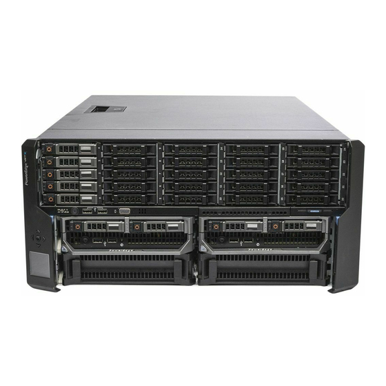
- Page 17 Item Indicator, Button, or Connector PSU 1 PSU 2 A Front Panel view of the chassis is given here with a table that lists the parts and devices available in the CMC. Figure 1. Front-Panel Features And Indicators—3.5 Inch Hard Disk Drive Chassis Item Indicator, Button, or Connector Description USB connectors (2)
-
Page 18: Supported Remote Access Connections
Provides access only to the active CMC. Supported Platforms CMC supports modular servers designed for the PowerEdge VRTX platform. For information about compatibility with CMC, see the documentation for your device. Dell Chassis Management Controller (CMC) Version 1.00 for Dell PowerEdge For the latest supported platforms, see the VRTX Release Notes available at dell.com/support/manuals. -
Page 19: Supported Web Browsers
Dell Chassis Management Controller (CMC) Version For the latest information about supported web browsers, see the 1.00 for Dell PowerEdge VRTX Release Notes located at dell.com/support/manuals. Managing Licenses The CMC features are available based on the license (CMC Express or CMC Enterprise) purchased. Only licensed features are available in the interfaces that allow you to configure or use CMC. -
Page 20: License Component State Or Condition And Available Operations
Learn More — Learn more about an installed license, or the licenses available for a component installed in the server. NOTE: For the Learn More option to display the correct page, make sure that *.dell.com is added to the list of Trusted Sites in the Security Settings. For more information, see the Internet Explorer help documentation. - Page 21 CMC Serial Port Active Directory and LDAP Slot and Function Assignment (PCIe and Virtual Adapters) RACADM (SSH, Local, and Remote) WS-MAN SNMP Telnet Web-based Interface Email Alerts LCD Deployment Extended iDRAC Management Enclosure Restore and Backup Server Module Firmware Update Remote Syslog Directory Services *For non-default directory service setting, only Reset...
-
Page 22: Viewing Localized Versions Of The Cmc Web Interface
RACADM Command Line Reference Guide available at dell.com/support/manuals. Other Documents You May Need To access the documents from the Dell Support site. Along with this Reference Guide, you can access the following guides available at dell.com/support/manuals. VRTX CMC Online Help provides information about using the Web interface. To access the Online Help, click •... -
Page 23: Accessing Documents From Dell Support Site
To access the documents from Dell Support site: 1. Go to dell.com/support/manuals. 2. In the Tell us about your Dell system section, under No, select Choose from a list of all Dell products and click Continue. 3. In the Select your product type section, click Software and Security. - Page 24 For Remote Enterprise System Management documents — dell.com/esmmanuals • For Serviceability Tools documents — dell.com/serviceabilitytools • For Client System Management documents — dell.com/OMConnectionsClient • For OpenManage Connections Enterprise systems management documents — dell.com/ OMConnectionsEnterpriseSystemsManagement • For OpenManage Connections Client systems management documents — dell.com/OMConnectionsClient...
-
Page 25: Installing And Setting Up Cmc
Understanding Redundant CMC Environment. Before You Begin Before setting up your CMC environment, download the latest version of CMC firmware for PowerEdge VRTX from dell.com/support/. Dell Systems Management Tools and Documentation DVD that was included with Also, make sure that you have the your system. -
Page 26: Basic Cmc Network Connection
For information about installing Dell OpenManage software components, see the Dell OpenManage Installation and Security User's Guide available on the DVD or at dell.com/support/manuals. You can also download the latest version of the Dell DRAC Tools from support.dell.com. Installing RACADM on a Linux Management Station Log in as root to the system running a supported Red Hat Enterprise Linux or SUSE Linux Enterprise Server operating system where you want to install the managed system components. -
Page 27: Uninstalling Racadm From A Linux Management Station
Configuring a Web Browser You can configure and manage CMC, servers, and modules installed in the chassis through a web browser. See the Dell Systems Software Support Matrix at dell.com/support/manuals. “Supported Browsers" section in the The CMC and the management station where you use your browser must be on the same network, which is called the management network . -
Page 28: Microsoft Phishing Filter
Mozilla FireFox To edit the exception list in Mozilla Firefox version 19.0: Start Mozilla Firefox. Click Tools → Options (for systems running on Windows), or click Edit → Preferences (for systems running on Linux). Click Advanced, and then click the Network tab. Click Settings. -
Page 29: Enabling Animations In Internet Explorer
CMC and iDRAC on each server and the network management ports for the switch I/O module are connected to a common internal network in the PowerEdge VRTX chassis. This allows the management network to be isolated from the server data network. It is important to separate this traffic for uninterrupted access to chassis management. - Page 30 CMC supports both IPv4 and IPv6 addressing modes. The configuration settings for IPv4 and IPv6 are independent of each other. Configuring CMC Network Using LCD Panel Interface Configuring CMC Using Quick Setup (DHCP) NOTE: You can customize the orientation of an LCD display (for rack or tower mode) by keeping the up-down buttons pressed for two seconds.
- Page 31 NOTE: The network speed and duplex mode settings are not available if Auto Negotiation is set to On, or if 1000MB (1Gbps) is selected. If auto negotiation is turned on for one device but not the other, the device that is using auto negotiation can determine the network speed of the other device, but not the duplex mode.
-
Page 32: Interfaces And Protocols To Access Cmc
For a list of supported Web browsers, see the “Supported Browsers” section in Dell System Software Support Matrix at dell.com/support/manuals. Remote RACADM command line Use this command line utility to manage CMC and its components. You can use... - Page 33 Interface Description managed system and uses the HTTPs channel. The –r option runs the RACADM command over a network. • Firmware RACADM is accessible by logging in to CMC using SSH or Telnet. You can run the firmware RACADM commands without specifying the CMC IP, user name, or password.
-
Page 34: Launching Cmc Using Other Systems Management Tools
You can set the chassis location in a data center and the chassis name to identify the chassis on the network (default name is Dell Rack System). For example, an SNMP query on the chassis name returns the name you configure. -
Page 35: Setting Date And Time On Cmc Using Cmc Web Interface
Setting Date and Time on CMC Using RACADM To set the date and time using the command line interface, see the config command and cfgRemoteHosts database Chassis Management Controller for PowerEdge VRTX RACADM Command Line Reference property group sections in the Guide available at dell.com/support/manuals. -
Page 36: Configuring Cmc Properties
Chassis • Run the RACADM cmcchangeover command. See the cmcchangeover command section in the Management Controller for PowerEdge VRTX RACADM Command Line Reference Guide available at dell.com/ support/manuals. • Run the RACADM racreset command on the active CMC. See the racreset command section in the Chassis Management Controller for PowerEdge VRTX RACADM Command Line Reference Guide available at dell.com/support/manuals.. -
Page 37: Cmc Failsafe Mode
CMC Failsafe Mode Similar to the failover protection offered by the redundant CMC, the PowerEdge VRTX enclosure enables the fail-safe mode to protect the servers and I/O module from not functioning. The fail-safe mode is enabled when a CMC is not in control of the chassis. -
Page 38: Configuring Power Button
Configuring Power Button To configure the chassis power button: In the left pane, click Chassis Overview → Front Panel → Setup. On the Front Panel Configuration page, under the Power Button Configuration section, select the Disable Chassis Power Button option, and then click Apply. The chassis power button is disabled. - Page 39 Mapping a Server to a DVD Drive To map the server to the chassis DVD drive: In the left pane, click Chassis Overview → Front Panel → Setup . On the Front Panel Configuration page, under the DVD Drive Configuration section: From the DVD Mapped drop-down menu, select one of the servers.
-
Page 41: Logging In To Cmc
To access the CMC web interface: Open a web browser supported on your system. Dell Systems Software Support Matrix located at For the latest information on supported web browsers, see the dell.com/support/manuals. -
Page 42: Logging In To Cmc Using A Smart Card
– CMC user name:– Active Directory user name: \ , / or @ . – LDAP user name: NOTE: This field is case-sensitive. In the Password field, type the user password. NOTE: For Active Directory user, the Username field is case-sensitive. Optionally, select a session timeout. -
Page 43: Logging Into Cmc Using Single Sign-On
RACADM provides a set of commands that allow you to configure and manage CMC through a text-based interface. RACADM can be accessed using a Telnet/SSH or serial connection, using the Dell CMC console on the KVM, or remotely using the RACADM command line interface installed on a management station. -
Page 44: Logging In To Cmc Using Public Key Authentication
You can use remote RACADM commands in scripts to configure multiple CMCs. You cannot run the scripts directly on the CMC web interface, because CMC does not support it. For more information about RACADM, see the Chassis Management Controller for PowerEdge VRTX RACADM Command Line Reference Guide . For more information about configuring multiple CMCs, see Configuring Multiple CMCs Using RACADM. -
Page 45: Updating Firmware
• RAID controllers Downloading CMC Firmware Before beginning the firmware update, download the latest firmware version from support.dell.com, and save it to your local system. Viewing Currently Installed Firmware Versions You can view the currently installed firmware versions using the CMC web interface or RACADM. -
Page 46: Viewing Currently Installed Firmware Versions Using Racadm
Allow Animations in Internet Explorer. Updating CMC Firmware Using RACADM To update CMC firmware using RACADM, use the fwupdate subcommand. For more information about RACADM Chassis Management Controller for PowerEdge VRTX RACADM Command Line Reference Guide . commands, see... -
Page 47: Updating Cmc Firmware Using Web Interface
Updating CMC Firmware Using Web Interface NOTE: Before you update the CMC firmware, make sure that you turn on the chassis, but turn off all the servers in the chassis. To update the CMC firmware using the CMC web interface: In the left pane, go to any of the following pages: –... -
Page 48: Updating Chassis Infrastructure Firmware Using Racadm
Chassis license. The iDRAC7 version must be 1.40.40 or later. For more information about the commands, see the Management Controller for PowerEdge VRTX RACADM Command Line Reference Guide . Updating Server iDRAC Firmware Using Web Interface To update the iDRAC firmware in the server: Go to any of the following pages: –... -
Page 49: Updating Server Component Firmware
Dell Update Packages (DUPs) are used to perform the firmware updates using Lifecycle Controller. The Operating System Driver Pack component DUP exceeds this limit and must be updated separately using the Extended Storage feature. -
Page 50: Enabling Lifecycle Controller
To narrow the category of a particular component or device based on types or models, automatically filter the selected components and devices. NOTE: Automatic filtering feature is important while using the Dell Update Package (DUP). The update programming of a DUP can be based on the type or model of a component or device. The automatic filtering behavior is designed to minimize the subsequent selection decisions after an initial selection is made. -
Page 51: Viewing Firmware Inventory
To filter components for Firmware Updates using RACADM, run the getversion command: racadm getversion -l [-m] [-f ] For more information, see the Chassis Management Controller for PowerEdge VRTX RACADM Command Line Reference Guide available at dell.com/support/manuals. Viewing Firmware Inventory You can view the summary of the firmware versions for all components and devices for all servers currently present in the chassis along with their status. -
Page 52: Viewing Firmware Inventory Using Cmc Web Interface
NOTE: To use this feature, you must have an Enterprise License. Viewing Firmware Inventory Using CMC Web Interface To view the firmware inventory: In the left pane, click Server Overview, and then click Update . On the Server Component Update page, view the firmware inventory details in the Component/Device Firmware Inventory section. -
Page 53: Viewing Firmware Inventory Using Racadm
Viewing Firmware Inventory Using RACADM To view firmware inventory using RACADM, use the getversion command: racadm getversion -l [-m] [-f ] Chassis Management Controller for PowerEdge VRTX RACADM Command Line Reference For more information, see the Guide available at dell.com/support/manuals. -
Page 54: Reinstalling Server Component Firmware
proper completion. After an operation has been submitted for scheduling, ensure that the confirmation message indicating that the operation has been successfully scheduled is acknowledged. Reinstalling Server Component Firmware You can reinstall the firmware image of the currently installed firmware for selected components or devices across one or more servers. -
Page 55: Upgrading Server Component Firmware Using Cmc Web Interface
This behavior is inherent in the Lifecycle Controller functionality and particularly the programming contained with the Dell Update Package (DUP). Currently, Dell Update Packages (DUP) that are less than 48 MB in size are supported. If the update file image size is greater, the job status indicates that the download has failed. If multiple server component updates are attempted on a server, the combined size of all the firmware update files may also exceed 48 MB. -
Page 56: Deleting Scheduled Server Component Firmware Jobs
Recovering iDRAC Firmware Using CMC iDRAC firmware is typically updated using iDRAC interfaces such as the iDRAC web interface, the SM-CLP command line interface, or operating system specific update packages downloaded from support.dell.com. For more information, iDRAC7User’s Guide . see the Early generations of servers can have corrupted firmware recovered using the new update iDRAC firmware process. -
Page 57: Viewing Chassis Information And Monitoring Chassis And Component Health
Viewing Chassis Information and Monitoring Chassis and Component Health You can view information and monitor the health of the following: • Active and standby CMCs • All severs and individual servers • IO Module • Fans • Power Supply Units (PSUs) •... -
Page 58: Chassis Graphics
Chassis Graphics The chassis is represented by the front and back views (the upper and lower images respectively). Servers, DVDs, HDDs, KVMs, and LCD are shown in the front view and the remaining components are shown in the back view. Component selection is indicated by a blue cast and is controlled by clicking the image of the required component. -
Page 59: Viewing Server Model Name And Service Tag
• Health and Performance, and Properties — Displays the active, critical, and non-critical events as displayed by the hardware logs and the performance data that vary with time. • Properties — Displays the component properties that do not vary with time, or that change only infrequently. •... -
Page 60: Viewing Information And Health Status Of Fans
Chassis Management Controller for PowerEdge VRTX For more information about the RACADM commands, see the RACADM Command Line Reference Guide available at dell.com/support/manuals. CMC generates an alert and increases the fan speeds when the following events occur: •... -
Page 61: Viewing Front Panel Properties
Enhanced Cooling Mode (ECM) — Is a feature in the CMC that allows increased cooling capacity for the servers installed within the PowerEdge VRTX chassis. Example uses for ECM are operation in a high ambient environment or using servers with high power (≥120W) CPUs installed. The increased cooling capacity is achieved by allowing the four chassis blower modules to run at a higher speed. -
Page 62: Viewing Lcd Information And Health
KVM sub-graphic and a corresponding text hint or screen tip is displayed. The text hint provides additional information about the KVM. Click the KVM sub-graphic to view the KVM information in the right pane. Alternatively, click Chassis Overview → Front Panel. On the Status page, under the KVM Properties section, you can view the status and properties of a KVM associated with the chassis. -
Page 63: Configuring Cmc
Configuring CMC Chassis Management Controller enables you to configure properties, set up users, and alerts to perform remote management tasks. Before you begin configuring the CMC, you must first configure the CMC network settings to allow CMC to be managed remotely. -
Page 64: Viewing And Modifying Cmc Network Lan Settings Using Cmc Web Interface
NOTE: You must have Chassis Configuration Administrator privilege to set up CMC network settings. Viewing and Modifying CMC Network LAN Settings Using CMC Web Interface To view and modify the CMC LAN network settings using CMC Web interface: In the left pane, click Chassis Overview, and then click Network. The Network Configuration page displays the current network settings. -
Page 65: Enabling Or Disabling Dhcp For The Cmc Network Interface Address
By default, for IPv4, the CMC requests and automatically obtains a CMC IP address from the Dynamic Host Configuration Protocol (DHCP) server. You can disable the DHCP feature and specify static CMC IP address, gateway, and subnet mask. For an IPv4 network, to disable DHCP and specify static CMC IP address, gateway, and subnet mask, type: racadm config -g cfgLanNetworking -o cfgNicUseDHCP 0 racadm config -g cfgLanNetworking -o cfgNicIpAddress... -
Page 66: Configuring Dns Settings (Ipv4 And Ipv6)
For IPv6, to set the preferred and secondary DNS IP Server addresses, type: racadm config -g cfgIPv6LanNetworking -o cfgIPv6DNSServer1racadm config -g cfgIPv6LanNetworking -o cfgIPv6DNSServer2 Configuring DNS Settings (IPv4 and IPv6) • CMC Registration — To register the CMC on the DNS server, type: racadm config -g cfgLanNetworking -o cfgDNSRegisterRac 1 NOTE: Some DNS servers only register names of 31 characters or fewer. -
Page 67: Configuring Network Security Settings
NOTE: IPv6 requires a minimum MTU of 1280. If IPv6 is enabled, and cfgNetTuningMtu is set to a lower value, the CMC uses an MTU of 1280. Configuring Network Security Settings You can configure the network security settings for IPv4 only. Configuring Network Security Settings Using CMC Web Interface NOTE: To perform the following tasks, you must have the Chassis Configuration Administrator privilege. -
Page 68: Configuring Virtual Lan Tag Properties For Cmc Using Web Interface
Remote Syslog — Enable CMC to log events to a remote server. To use this feature, you must have an Enterprise license. CMC includes a web server that is configured to use the industry-standard SSL security protocol to accept and transfer encrypted data from and to clients over the Internet. The web server includes a Dell self-signed SSL Digital Certificate... -
Page 69: Configuring Services Using Cmc Web Interface
• cfgRacTuneRemoteRacadmEnable Chassis Management Controller for PowerEdge VRTX RACADM For more information about these objects, see the Command Line Reference Guide available at dell.com/support/manuals. If the firmware on the server does not support a feature, configuring a property related to that feature displays an error. -
Page 70: Configuring Cmc Extended Storage Card
For example: $ racadm getconfig -g cfgSessionManagement -m server-1 # cfgSsnMgtWebServerMaxSessions=N/A # cfgSsnMgtWebServerActiveSessions=N/A # cfgSsnMgtWebServerTimeout=N/A # cfgSsnMgtSSHMaxSessions=N/A # cfgSsnMgtSSHActiveSessions=N/A # cfgSsnMgtSSHTimeout=N/A # cfgSsnMgtTelnetMaxSessions=N/A # cfgSsnMgtTelnetActiveSessions=N/A # cfgSsnMgtTelnetTimeout=N/A Configuring CMC Extended Storage Card You can enable or repair the optional Removable Flash Media for use as an extended non-volatile storage. Some CMC features depend on extended nonvolatile storage for their operation. -
Page 71: Adding Members To Chassis Group
On the Chassis Group page, under Role, select Leader. A field to add the group name is displayed. Type the group name in the Group Name field, and then click Apply. NOTE: The same rules that apply for a domain name apply to the group name. When the chassis group is created, the GUI automatically switches to the Chassis Group page. -
Page 72: Disabling An Individual Member At The Member Chassis
Click Setup → Group Administration. In the Chassis Group page, under Role, select None, and then click Apply. The lead chassis then communicates to all the members that they have been removed from the group. The lead chassis can be assigned as a leader or member of a new group. If a network issue prevents contact between the leader and the member, the member chassis may not receive the message. -
Page 73: Server Inventory For Mcm Group
Table 6. Configuration Service Properties Property Navigation SNMP configuration In the left pane, click Chassis Overview → Network → Services → SNMP. Chassis remote logging In the left pane, click Chassis Overview → Network → Services → Remote Syslog. User authentication using LDAP and Active Directory In the left pane, click Chassis Overview →... -
Page 74: Configuring Multiple Cmcs Using Racadm
The following table lists the specific data fields and specific requirements for fields to be reported for each server: Table 7. Server Module Inventory Field Descriptions Data Field Example Chassis Name Data Center Chassis Leader Chassis IP Address 192.168.0.1 Slot Location Slot Name SLOT-01 Host Name... -
Page 75: Creating A Cmc Configuration File
NOTE: For more information about the getconfig subcommand, see the PowerEdge VRTX RACADM Command Line Reference Guide . RACADM parses the .cfg file when it is first loaded on to the CMC to verify that a valid group and object names are present, and that simple syntax rules are being followed. -
Page 76: Parsing Rules
Chassis Management indexes, and other parameters. For a complete list of objects and groups, see the Controller for PowerEdge VRTX RACADM Command Line Reference Guide . CAUTION: Use the racresetcfg subcommand to reset the database and the CMC Network Interface settings to the original default settings and remove all users and user configurations. -
Page 77: Modifying The Cmc Ip Address
Any character to the right of the = (for example, a second =, a #, [, ], and so on) is taken as-is. These characters are valid modem chat script characters. [cfgLanNetworking] -{group name} cfgNicIpAddress=143.154.133.121 {object value} • The .cfg parser ignores an index object entry. You cannot specify which index is used. -
Page 78
This file is updated as follows: # Object Group "cfgLanNetworking" [cfgLanNetworking] cfgNicIpAddress=10.35.9.143 # comment, the rest of this line is ignored cfgNicGateway=10.35.9.1 The command racadm config -f
.cfg parses the file and identifies any errors by line number. A correct file updates the proper entries. Additionally, you can use the same getconfig command from the previous example to confirm the update. -
Page 79: Configuring Servers
Configuring Servers You can configure the following settings of a server: • Slot Names • iDRAC Network Settings • DRAC VLAN Tag Settings • First Boot Device • Server FlexAddress • Remote File Share • BIOS Settings Using Server Clone Configuring Slot Names Slot names are used to identify individual servers. -
Page 80: Configuring Idrac Network Settings
Dell OpenManage Server installed on the server. For more information about the OMSA agent, see the Administrator User's Guide available at dell.com/support/manuals. To save the settings, click Apply. To restore the default slot name (SLOT-01 through SLOT-4) on the basis of a server's slot position) to a server, click Restore Default Value. - Page 81 Setting Description Enable iDRAC IPMI over LAN Enables or disables the IPMI over LAN channel for each iDRAC present in the chassis. By default, this option is selected. Enable iDRAC IPv4 DHCP Enables or disables DHCP for each iDRAC present in the chassis.
-
Page 82: Modifying Idrac Network Settings For Individual Server Idrac
to allow or not allow the password change. If there are network configuration settings that differ from the current iDRAC settings, the user is prompted to either accept or reject the changes. NOTE: If there is a LAN or IPMI over LAN difference, the user is prompted to accept the QuickDeploy IP address setting. -
Page 83: Configuring Idrac Vlan Tag Settings
RACADM Command Line Reference Guide For more information about the property default values and ranges, see the for iDRAC7 and CMC available at dell.com/support/manuals. Configuring iDRAC VLAN Tag Settings VLANs are used to allow multiple virtual LANs to co-exist on the same physical network cable and to segregate the network traffic for security or load management purposes. -
Page 84: Setting First Boot Device For Multiple Servers Using Cmc Web Interface
the first boot device in the BIOS boot order, until it is changed again either from the CMC web interface or from the BIOS boot sequence. NOTE: The first boot device setting in CMC web Interface overrides the system BIOS boot settings. The boot device that you specify must exist and contain a bootable media. -
Page 85: Setting First Boot Device Using Racadm
To set the first boot device, use the cfgServerFirstBootDevice object. To enable boot once for a device, use the cfgServerBootOnce object. For more information about these objects, see the Chassis Management Controller for PowerEdge VRTX RACADM Command Line Reference Guide available at dell.com/support/manuals. Configuring Server FlexAddress... -
Page 86: Configuring Bios Settings Using Server Clone
Configuring BIOS Settings Using Server Clone The server cloning feature allows you to apply all BIOS settings from a specified server to one or more servers. Only the BIOS settings that can be modified and intended to be replicated across servers can cloned. To use this feature, you must have an Enterprise License. -
Page 87: Applying Profile
1. In the left pane, click Chassis Overview → Server Overview → Setup → Profiles. 2. On the BIOS Profiles page, in the Apply Profile section, click Manage Profiles. The Manage BIOS Profiles page is displayed. • To edit a profile, click Edit. •... -
Page 88: Completion Status And Troubleshooting
Completion Status And Troubleshooting To check the completion status of an applied BIOS profile: In the left pane, click Chassis Overview → Server Overview → Setup → Profiles. On the BIOS Profiles page, note down the Job ID (JID) of the submitted job from the Recent Profile Log section. In the left pane, click Server Overview →... -
Page 89: Launching Remote Console
The browser on host system allows pop-up windows (pop-up blocking is disabled). iDRAC User’s Guide Remote Console can also be launched from the iDRAC Web interface. For more details, see the available at dell.com/support/manuals. Launching Remote Console from Chassis Health Page To launch a remote console from the CMC Web interface: In the left pane, click Chassis Overview, and then click Properties . -
Page 91: Configuring Cmc To Send Alerts
Enabling Or Disabling Alerts Using RACADM To enable or disable generating alerts, use the cfgIpmiLanAlertEnable RACADM object. For more information, see the Chassis Management Controller for PowerEdge VRTX RACADM Command Line Reference Guide . Filtering Alerts You can filter alerts on the basis of category and severity. -
Page 92: Configuring Alert Destinations
Chassis Management To set an event alert, run the eventfilters command. For more information, see the Controller for PowerEdge VRTX RACADM Command Line Reference Guide available at dell.com/support//manuals. Configuring Alert Destinations The management station uses Simple Network Management Protocol (SNMP) to receive data from CMC. - Page 93 management stations. The community string on the Chassis Overview → Network → Services page is the community string that management stations use to query the SNMP daemon on CMC. – Under Enabled , select the option corresponding to the destination IP to enable the IP address to receive the traps.
-
Page 94: Configuring E-Mail Alert Settings
To test an event trap for an alert destination, type: racadm testtrap -iwhere is a value between 1–4 representing the alert destination you want to test. If you are not sure about the index number, run the following command: racadm getconfig -g cfgTraps -i ... -
Page 95
(1–4). To determine whether an index has previously configured values, type racadm getconfig -g cfgEmailAlert — I
. If the index is configured, values appear for the cfgEmailAlertAddress and cfgEmailAlertEmailName objects. Chassis Management Controller for PowerEdge VRTX RACADM Command Line For more information, see the Reference Guide available at dell.com/support/manuals. -
Page 97: Configuring User Accounts And Privileges
Configuring User Accounts and Privileges You can setup user accounts with specific privileges (role-based authority) to manage your system with CMC and maintain system security. By default, CMC is configured with a local administrator account. The default user name is rootand the password is calvin. - Page 98 Privilege Description themselves. For this reason, slot names and slot priorities can be added or changed whether or not servers are present in the slots. When a server is moved to a different chassis, it inherits the slot name and priority assigned to the slot it occupies in the new chassis.
- Page 99 Privilege Description chassis user does not have the Server Administrative privilege on the chassis. Server Configuration Administrator: • Set IP address • Set gateway • Set subnet mask • Set first boot device Configure Users: • Set iDRAC root password •...
- Page 100 User Group Privileges Granted • Fabric A Administrator Power User • Login • Clear Logs Administrator • Chassis Control Administrator (Power commands) • Server Administrator • Test Alert User • Fabric A Administrator Guest User Login Custom Select any combination of the following permissions: •...
-
Page 101: Modifying Root User Administrator Account Settings
Modifying Root User Administrator Account Settings For added security, it is strongly recommended that you change the default password of the root (User 1) account. The root account is the default administrative account that is shipped with CMC. To change the default password for the root account: In the left pane, click Chassis Overview, and then click User Authentication. - Page 102 NOTE: For a list of valid bit mask values for specific user privileges, see the PowerEdge VRTX RACADM Command Line Reference Guide . The default privilege value is 0, which indicates that the privileges of a user are not enabled.
-
Page 103: Configuring Active Directory Users
• Standard schema solution that uses Microsoft’s default Active Directory group objects only. Extended schema solution that has customized Active Directory objects provided by Dell. All the access control • objects are maintained in Active Directory. It provides maximum flexibility to configure user access on different... -
Page 104: Standard Schema Active Directory Overview
Standard Schema Active Directory Overview As shown in the following figure, using standard schema for Active Directory integration requires configuration on both Active Directory and CMC. In Active Directory, a standard group object is used as a role group. A user who has CMC access is a member of the role group. -
Page 105: Configuring Standard Schema Active Directory
Configuring Standard Schema Active Directory To configure CMC for an Active Directory login access: On an Active Directory server (domain controller), open Active Directory Users and Computers Snap-in. Using the CMC Web interface or RACADM: a) Create a group or select an existing group. b) Configure the role privileges. - Page 106 IP address of the domain controller> NOTE: Enter the FQDN of the domain controller, not the FQDN of the domain. For example, enter servername.dell.com instead of dell.com. NOTE: At least one of the three addresses is required to be configured. CMC attempts to connect to each of the configured addresses one-by-one until it makes a successful connection.
-
Page 107: Extended Schema Active Directory Overview
To extend the schema in Microsoft's Active Directory, Dell received unique OIDs, unique name extensions, and uniquely linked attribute IDs for the attributes and classes that are added into the directory service. -
Page 108: Configuring Extended Schema Active Directory
CMCs and give user3 a login privilege to the RAC2 card. When adding Universal Groups from separate domains, create an Association Object with Universal Scope. The Default Association objects created by the Dell Schema Extender Utility are Domain Local Groups and does not work with Universal Groups from other domains. - Page 109 • LDIF script file If you use the LDIF script file, the Dell organizational unit is not added to the schema. Dell Systems Management Tools and Documentation DVD The LDIF files and Dell Schema Extender are located on your in the following respective directories: •...
- Page 110 Class Type Auxiliary Class SuperClasses None Attributes dellIsLoginUser dellIsCardConfigAdmin dellIsUserConfigAdmin dellIsLogClearAdmin dellIsServerResetUser dellIsTestAlertUser dellIsDebugCommandAdmin dellPermissionMask1 dellPermissionMask2 Table 18. dellPrivileges Class 1.2.840.113556.1.8000.1280.1.1.1.4 Description Used as a container Class for the Dell Privileges (Authorization Rights). Class Type Structural Class SuperClasses User Attributes dellRAC4Privileges...
- Page 111 Table 19. dellProduct Class 1.2.840.113556.1.8000.1280.1.1.1.5 Description The main class from which all Dell products are derived. Class Type Structural Class SuperClasses Computer Attributes dellAssociationMembers Table 20. List of Attributes Added to the Active Directory Schema Assigned OID/Syntax Object Identifier Single Valued...
- Page 112 Attribute: dellPermissionsMask2 OID: 1.2.840.113556.1.8000.1280.1.6.2.2 Integer (LDAPTYPE_INTEGER) Installing Dell Extension to the Active Directory Users and Computers Snap-In When you extend the schema in Active Directory, you must also extend the Active Directory Users and Computers Snap- in so the administrator can manage RAC (CMC) devices, users and user groups, RAC associations, and RAC privileges.
- Page 113 For more information about the Active Directory Users and Computers Snap-in, see Microsoft documentation. Adding CMC Users And Privileges To Active Directory Using the Dell-extended Active Directory Users and Computers Snap-in, you can add CMC users and privileges by creating RAC device, association, and privilege objects. To add each object, perform the following: •...
- Page 114 Adding Objects To Association Object Using the Association Object Properties window, you can associate users or user groups, privilege objects, and RAC devices or RAC device groups. If your system is running on Microsoft Windows 2000 operating system or later version, use Universal Groups to span domains with your user or RAC objects.
- Page 115 Click Apply to save the settings. NOTE: You must apply the settings before continuing. If you do not apply the settings, the settings are lost when you navigate to the next page. In the Extended Schema Settings section, type the CMC device name and the domain name. If you have enabled certificate validation, you must upload the domain forest root certificate authority-signed certificate to CMC.
-
Page 116: Configuring Generic Ldap Users
NOTE: In this case, you do not have to upload a CA certificate. To enforce the certificate validation during SSL handshake (optional): racadm config -g cfgActiveDirectory -o cfgADCertValidationEnable 1 In this case, you must upload a CA certificate: racadm sslcertupload -t 0x2 -f < ADS root CA certificate > NOTE: If certificate validation is enabled, specify the Domain Controller Server addresses and the FQDN. -
Page 117: Configuring Generic Ldap Directory Service Using Cmc Web Interface
For example: _ldap._tcp.dell.com where ldap is the service name and dell.com is the search domain. Click Apply to save the settings. NOTE: You must apply the settings before continuing. If you do not apply the settings, the settings are lost when you navigate to the next page. -
Page 118: Configuring Generic Ldap Directory Service Using Racadm
_ldap._tcp.domainname.com ldap in the above query is the cfgLDAPSRVLookupServiceName property. cfgLDAPSRVLookupDomainName is configured to be domainname.com. Chassis Management Controller for PowerEdge VRTX For more information about the RACADM commands, see the RACADM Command Line Reference Guide available at dell.com/support/manuals. -
Page 119: Configuring Cmc For Single Sign-On Or Smart Card Login
Configuring CMC For Single Sign-On Or Smart Card Login This section provides information to configure CMC for Smart Card login and Single Sign-On (SSO) login for Active Directory users. SSO uses Kerberos as an authentication method allowing users, who have signed in as an automatic- or single sign-on to subsequent applications such as Exchange. -
Page 120: Cmc
• Each CMC must have an Active Directory account. • CMC must be a part of the Active Directory domain and Kerberos Realm. Prerequisites For Single Sign-On Or Smart Card Login The pre-requisites to configure SSO or Smart Card logins are: •... -
Page 121: Configuring Browser For Sso Login
For information about configuring CMC for Extended Schema Active Directory, see Extended Schema Active Directory Overview. Configuring Browser For SSO Login Single Sign-On (SSO) is supported on Internet Explorer versions 6.0 and later, and Firefox versions 3.0 and later. NOTE: The following instructions are applicable only if CMC uses Single Sign-On with Kerberos authentication. Internet Explorer To configure Internet Explorer for Single Sign-On: In the Internet Explorer, select Tools →... -
Page 122: Uploading Keytab File
A command success indicates that CMC is able to acquire Kerberos credentials and access the user's Active Directory account. If the command is not successful, resolve the error and run the command again. For more Chassis Management Controller for PowerEdge VRTX RACADM Command Line Reference information, see the Guide on dell.com/support/manuals. -
Page 123: Configuring Cmc To Use Command Line Consoles
Chassis Management information about using the RACADM commands in CMC through the command line console, see Controller for PowerEdge VRTX RACADM Command Line Reference Guide . CMC Command Line Console Features The CMC supports the following serial, Telnet, and SSH console features: •... -
Page 124: Using Ssh With Cmc
Chassis cfgSsnMgtSshIdleTimeout property. For more information about the RACADM commands, see the Management Controller for PowerEdge VRTX RACADM Command Line Reference Guide available at dell.com/support/ Manuals. CMC also supports Public Key Authentication (PKA) over SSH. This authentication method improves SSH scripting automation by removing the need to embed or prompt for user ID/password. -
Page 125: Configure Public Key Authentication Over Ssh
09:00:00 x.x.x.x 06/16/2009 09:00:00 Chassis Management Controller for PowerEdge VRTX RACADM For more information about the sshpkauth, see the Command Line Reference Guide . Generating Public Keys for Systems Running Windows Before adding an account, a public key is required from the system that accesses the CMC over SSH. There are two ways to generate the public/private key pair: using PuTTY Key Generator application for clients running Windows or ssh- keygen CLI for clients running Linux. -
Page 126
Chassis NOTE: You can use only the file upload option with remote RACADM. For more information, see Management Controller for PowerEdge VRTX RACADM Command Line Reference Guide . To add a public key using the text upload option, enter: racadm sshpkauth –i svcacct –k 1 –p 0xfff –t “
”... -
Page 127: Configuring Terminal Emulation Software
To delete all public keys, run the following command: racadm sshpkauth –i svcacct –k all –d Configuring Terminal Emulation Software CMC supports a serial text console from a management station running one of the following types of terminal emulation software: •... -
Page 128: Connecting To Servers Or I/O Module Using Connect Command
For servers, serial console redirection can be accomplished using: • CMC command line interface (CLI) or the RACADM connect command. For more information about running the Chassis Management Controller for PowerEdge VRTX RACADM Command Line RACADM commands, see the Reference Guide . -
Page 129: Configuring The Managed Server Bios For Serial Console Redirection
You can use a Remote Console session to connect to the managed system using the iDRAC7 web interface (see the iDRAC7 User’s Guide on dell.com/support/manuals). By default, the Serial communication in the BIOS is turned off. To redirect host text console data to Serial over LAN, you must enable console redirection through COM1. -
Page 130: Configuring Linux For Server Serial Console Redirection After Boot
Edit the /etc/grub.conf file as follows: Locate the general setting sections in the file and type the following two new lines: serial --unit=1 --speed=57600 terminal --timeout=10 serial Append two options to the kernel line: kernel console=ttyS1,57600 If the /etc/grub.conf contains a splashimage directive, comment it out. The following example shows the changes described in this procedure. - Page 131 The following example shows the file with the new line. # inittab This file describes how the INIT process # should set up the system in a certain # run-level. # Author: Miquel van Smoorenburg # Modified for RHS Linux by Marc Ewing and # Donnie Barnes # Default runlevel.
- Page 132 Add a new line, with the name of the serial tty for COM2: ttyS1 The following example shows a sample file with the new line. vc/1 vc/2 vc/3 vc/4 vc/5 vc/6 vc/7 vc/8 vc/9 vc/10 vc/11 tty1 tty2 tty3 tty4 tty5 tty6 tty7...
-
Page 133: Using Flexaddress And Flexadress Plus Cards
Using FlexAddress and FlexAdress Plus Cards This section provides information about FlexAddress, FlexAddress Plus Cards, and configuring and using these the cards. NOTE: The FlexAddress feature is licensed, and you must an Enterprise License to use this. About FlexAddress The FlexAddress feature is an optional upgrade that allows server modules to replace the factory-assigned World Wide Name and Media Access Control (WWN/MAC) network IDs with WWN/MAC IDs provided by the chassis. -
Page 134: Activating Flexaddress
The updates (listed in the following table) include server module BIOS and CMC firmware. You must apply these updates before you enable FlexAddress. If these updates are not applied, the FlexAddress feature may not function as expected. NOTE: FlexAddress cannot be activated on the DELL monolithic servers. Table 25. Prerequisites for Activating FlexAddress Component... -
Page 135: Activating Flexaddress Plus
For these servers, upgrading to FlexAddress Plus enables full optimization of the WWN/MACs configuration. Contact Dell to obtain support for the FlexAddress Plus feature. To activate the FlexAddress Plus feature, the following software updates are required: server BIOS, server iDRAC, and CMC firmware. -
Page 136: Deactivating Flexaddress
Dell Feature Cards may contain more than one feature. Once any feature included on a Dell Feature Card has been activated on a chassis, any other features that may be included on that Dell Feature Card cannot be activated on a different chassis. -
Page 137: Viewing Flexaddress Information For Chassis
Viewing FlexAddress Information For Chassis FlexAddress status information can be displayed for the entire chassis. The status information includes whether the feature is active and an overview of the FlexAddress status for each server. To view the chassis FlexAddress status using the CMC web interface, click Chassis Overview → Setup . The General Chassis Settings page is displayed. -
Page 138: Viewing Flexaddress Information For Individual Servers
FlexAddress separately, you must install the SD feature card using the instructions in the Controller (CMC) Secure Digital (SD) Card Technical Specification document available at dell.com/support/manuals. The server must be turned off before you begin configuration. You can enable or disable FlexAddress on a per-fabric–... -
Page 139: Configuring Flexaddress For Chassis-Level Fabric And Slots
For more information about the setflexaddr command, see the RACADM Command Line Reference Guide . NOTE: If you purchase the FlexAddress or FlexAddressPlus feature with your Dell PowerEdge VRTX, it is pre- installed and enabled for all slots and fabrics. To purchase this feature, contact Dell at dell.com. -
Page 140: Viewing World Wide Name/Media Access Control (Wwn/Mac) Ids
Viewing World Wide Name/Media Access Control (WWN/MAC) IDs The WWN/MAC Summary page allows you to view the WWN configuration and MAC address of a slot in the chassis. Fabric Configuration The Fabric Configuration section displays the type of Input/Output fabric that is installed for Fabric A. A green check mark indicates that the fabric is enabled for FlexAddress. -
Page 141: Flexaddress Dell Software License Agreement
Software. If you are a commercial customer of Dell or a Dell affiliate, you hereby grant Dell, or an agent... - Page 142 (a) return of the price paid for the Software or (b) replacement of any disk not meeting this warranty that is sent with a return authorization number to Dell, at your cost and risk. This limited warranty is void if any disk damage has resulted from accident, abuse, misapplication, or service or modification by someone other than Dell.
-
Page 143: Managing Fabrics
Managing Fabrics The chassis supports a fabric type, which is Fabric A. Fabric A is used by the single I/O Module, and is always connected to the on-board Ethernet adapters of the servers. The chassis has only one I/O module (IOM), where the IOM is a pass-through or switch module. The I/O Module is classified as group A. -
Page 144: Configuring Network Settings For Iom
Configuring Network Settings for IOM Using RACADM To configure the network settings for an IOM by using RACADM, set the date and time. See the deploy command section Chassis Management Controller for PowerEdge VRTX RACADM Command Line Reference Guide . in the You can set the user name, password, and SNMP string for the IOM using the RACADM deploy command: racadm deploy -m switch -u... -
Page 145: Managing And Monitoring Power
However, this capacity varies on the basis of power redundancy policy you select. The PowerEdge VRTX enclosure can be configured for any of the two redundancy policies that affect PSU behavior and determine how chassis Redundancy state is reported to administrators. -
Page 146: Ac Redundancy Policy
AC Redundancy Policy The purpose of the AC redundancy policy is to enable a modular enclosure system to operate in a mode in which it can tolerate AC power failures. These failures may originate in the AC power grid, the cabling and delivery, or a PSU itself. When you configure a system for AC redundancy, the PSUs are divided into grids: PSUs in slots 1 and 2 are in the first grid while PSUs in slots 3 and 4 are in the second grid. -
Page 147: Default Redundancy Configuration
To operate remaining PSUs at their maximum efficiency, use the following power redundancy modes: • PSU Redundancy mode with DPSE provides power efficiency. At least two supplies are online, with one PSU required to power the configuration, and one to provide redundancy in case of a PSU failure. PSU Redundancy mode offers protection against the failure of any one PSU, but offers no protection in the event of an AC grid loss. -
Page 148: Power Supply Redundancy
To help datacenters allocate power for their enclosures, the PowerEdge VRTX allows you to specify a System Input Power Cap to make sure that the overall chassis AC power draw stays within a given threshold point. CMC first makes sure that enough power is available to run the fans, I/O module, storage adapters, physical disk drive, main board, and CMC itself. -
Page 149: Server Slot Power Priority Settings
System Input Max Power Capacity , and the user- priority servers may get less power than priority-one servers based on System Input Power Cap . configured setting of Configuration changes, such as an additional server, shared HDDs, or PCIe cards in the chassis, may require the System Input Power Cap to be increased. -
Page 150: Assigning Priority Levels To Servers Using Cmc Web Interface
Assigning Priority Levels To Servers Using CMC Web Interface To assign priority levels: In the left pane, click Server Overview → Power → Priority . The Server Priority page lists all the servers in the chassis. From the Priority drop-down menu, select a priority level (1–9, where 1 is the highest priority) for one, multiple, or all servers. -
Page 151: Viewing Power Budget Status Using Racadm
Chassis For more information about getpbinfo, including output details, see the getpbinfo command section in the Management Controller for PowerEdge VRTX RACADM Command Line Reference Guide . Redundancy Status and Overall Power Health The redundancy status is a factor in determining the overall power health. When the power redundancy policy is set, for example, to AC Redundancy and the redundancy status indicates that the system is operating with redundancy, the overall power health is typically OK. -
Page 152: Power Supply And Redundancy Policy Changes In System Event Log
This occurs if the administrator had configured power limit for the chassis lower than the full power allocation to the servers or if insufficient power is available to servers requiring high power. The following table provides the actions taken by CMC, when a new server is powered on in the scenario described earlier. -
Page 153: Configuring Power Budget And Redundancy
AC input received The power input for power supply is lost. AC input lost The power input for power supply has been restored. DC output produced Power supply is operating normally. DC output lost Power supply failed. Events related to changes in the power redundancy status that record entries in the SEL are redundancy loss and redundancy regain for the modular enclosure that is configured for either an AC Redundancy power policy or Power Supply Redundancy power policy. -
Page 154: Maximum Power Conservation Mode
Maximum Power Conservation Mode This is enabled only when AC redundancy is selected. CMC performs maximum power conservation when: • Maximum conservation mode is enabled • An automated command line script, issued by a UPS device, enables maximum conservation mode. In maximum power conservation mode, all servers start functioning at their minimum power levels, and all subsequent server power allocation requests are denied. -
Page 155: Configuring Power Budget And Redundancy Using Cmc Web Interface
• Redundancy policy • Remote power logging • Server performance over power redundancy • Dynamic power supply engagement • Server power of 11th generation and earlier servers OPMC then manages prioritization and power of 12th generation server nodes in the chassis from the budget available after allocation of power to chassis infrastructure and prior generation server nodes. -
Page 156
To enable and set the redundancy policy: Open a serial/Telnet/SSH text console to CMC and log in. Set properties as needed: – To select a redundancy policy, type: racadm config -g cfgChassisPower -o cfgChassisRedundancyPolicy
value > is 0 (AC Redundancy), and 1 (Power Supply Redundancy). The default value is 0. where <... -
Page 157: Executing Power Control Operations
-g cfgChassisPower -o cfgChassisServerBasedPowerMgmtMode 0 For information about RACADM commands for chassis power, see the config, getconfig, getpbinfo, and Chassis Management Controller for PowerEdge VRTX RACADM Command Line cfgChassisPower sections in the Reference Guide . Executing Power Control Operations You can execute the following power control operation for the chassis, servers, and IOM. -
Page 158: Executing Power Control Operations On A Server
Executing Power Control Operations on a Server You can remotely perform power management actions for multiple servers at a time or an individual server in the chassis. NOTE: To perform power management actions, you must have the Chassis Configuration Administrator privilege. Executing Power Control Operations for Multiple Servers Using CMC Web Interface To execute power control operation for multiple servers using the Web interface:... -
Page 159: Executing Power Control Operations On The Iom Using Racadm
Executing Power Control Operations on the IOM Using RACADM To execute power control operations on the IOM using RACADM, open a serial/Telnet/SSH text console to CMC, log in, and type: racadm chassisaction -m switchaction > indicates the operation you want to execute: power cycle. where <... -
Page 161: Managing Chassis Storage
Managing Chassis Storage On the Dell PowerEdge VRTX, you can perform the following operations: • View the status of physical disks drives and storage controllers. • View the properties of controllers, physical disk drives, virtual disks, and enclosures. • Set up controllers, physical disk drives, and virtual disks. -
Page 162: Viewing Controller Properties Using Cmc Web Interface
. For more information about Controllers, see the Viewing Controller Properties Using RACADM To view controller properties using RACADM, run the command racadm raid get controllers -o Chassis Management Controller for PowerEdge VRTX RACADM Command Line Reference For more information, see the Guide . -
Page 163: Viewing Physical Disk Drives Properties Using Racadm
Viewing Physical Disk Drives Properties Using RACADM To view the properties of physical disk drives using RACADM, run the command racadm raid get pdisks —o Chassis Management Controller for PowerEdge VRTX RACADM Command Line Reference For more information, see the Guide . -
Page 164: Viewing Virtual Disk Properties Using Racadm
Viewing Virtual Disk Properties Using RACADM To view virtual disk properties using RACADM, run the command racadm raid get vdisks -o Chassis Management Controller for PowerEdge VRTX RACADM Command Line Reference For more information, see the Guide . Creating Virtual Disk Using CMC Web Interface Make sure that the physical disk is installed in the chassis. -
Page 165: Viewing Enclosure Properties Using Cmc Web Interface
NOTE: If you select Delete, the following message is shown indicating that deleting a virtual disk will permanently delete data available in that virtual disk. Deleting the virtual disk removes the virtual disk from the controller's configuration. Initializing the virtual disk permanently erases data from the virtual disk. -
Page 167: Managing Pcie Slots
Managing PCIe Slots By default, all slots are unmapped. You can do the following: • View the status of all PCIe Slots in the chassis. • Assign or unassign a PCIe slot to the servers. Consider the following before assigning a PCIe slot to a server: •... -
Page 168: Managing Pcie Slots Using Racadm
You can assign or unassign a PCIe slot to a server by using the RACADM commands. Some of the commands are given Chassis Management Controller for PowerEdge here. For more information about the RACADM commands, see the VRTX RACADM Command Line Reference Guide available at dell.com/support/Manuals. • To view the current assignment of PCIe devices to servers, run the following command: racadm getpiecfg -a •... -
Page 169: Troubleshooting And Recovery
Supported Interfaces • CLI RACADM • Remote RACADM • Telnet RACADM racdump includes the following subsystems and aggregates the following RACADM commands. For more information RACADM Command Line Reference Guide for CMC in PowerEdge VRTX . about racdump, see the... -
Page 170: Downloading Snmp Management Information Base (Mib) File
In the left pane, click Chassis Overview → Network → Services → SNMP. In the SNMP Configuration section, click Save to download the CMC MIB file to your local system. Dell OpenManage Server Administrator SNMP Reference For more information about the SNMP MIB file, see the Guide at dell.com/support/manuals. - Page 171 Resolution A: Check and replace the AC cord. Check and confirm that the power distribution unit providing power to the power supply is operating as expected. If the failure still persists, call Dell customer service for replacement of the power supply.
-
Page 172: Troubleshooting Alerts
• Problem: Overall server performance decreases when the ambient temperature increases in the data center. – Resolution: This can occur if the System Input Power Cap has been configured to a value that results in an increased power need by fans having to be made up by reduction in the power allocation to the servers. -
Page 173: Viewing Chassis Log
NOTE: CMC creates a new log entry indicating that the log was cleared. NOTE: To clear the hardware log, you must have the Clear Logs Administrator privilege. Viewing Hardware Logs Using RACADM To view the hardware log using RACADM, open a serial/Telnet/SSH text console to CMC, log in, and type: racadm getsel To clear the hardware log, type: racadm clrsel... -
Page 174: Resetting Components
Resetting Components You can reset the active CMC, or to virtually reset servers making them to behave as if they were removed and reinserted. If the chassis has a standby CMC, resetting the active CMC causes a failover and the standby CMC becomes active. -
Page 175: Interpreting Led Colors And Blinking Patterns
You can also check the ntpd status by typing the following racadm command: racadm getractime –n If the ‘*’ is not displayed for one of the configured servers, the settings may not be configured correctly. The output of this command contains detailed NTP statistics that may be useful in debugging the problem. If you attempt to configure a Windows-based NTP server, it may help to increase the MaxDist parameter for ntpd. - Page 176 Component LED Color, Blinking Pattern Status Blue, glowing steadily Active Blue, blinking User-enabled module identifier Amber, glowing steadily Not used Amber, blinking Fault Blue, dark Standby Server Green, glowing steadily Turned on Green, blinking Firmware is being uploaded Green, dark Turned off Blue, glowing steadily Normal...
-
Page 177: Troubleshooting Non-Responsive Cmc
Component LED Color, Blinking Pattern Status Amber, glowing steadily Fan type not recognized, update the CMC firmware Amber, blinking Fan fault; tachometer out of range Amber, dark Not used (Oval) Green, glowing steadily AC OK (Oval) Green, blinking Not used (Oval) Green, dark AC Not OK Amber, glowing steadily... -
Page 178: Recovering Firmware Image
FW images] CMC2 has corrupted images – If the prompt indicates a self test failure, there are no serviceable components on CMC. CMC is bad and must be returned to Dell. – If the prompt indicates Bad FW Images, complete tasks in Recovering Firmware Image. -
Page 179: Troubleshooting Controller
The trace log may also contain CMC firmware-specific error codes that are related to the internal CMC firmware, not the managed system’s operating system. Troubleshooting Controller To troubleshoot a controller: In the left pane, click Chassis Overview → Storage → Controllers → Troubleshooting. On the Controller Troubleshooting page, from the Actions drop-down list for the respective controller, select any one of the following, and then click Apply. -
Page 181: Using Lcd Panel Interface
Using LCD Panel Interface You can use the LCD panel on the chassis to perform configuration and diagnostics, and to obtain status information about the chassis and its contents. The following figure illustrates the LCD panel. The LCD screen displays menus, icons, pictures, and messages. Figure 2. -
Page 182: Main Menu
Accept/Yes — Highlight and press the center button to accept a change and return to the previous screen. Skip/Next — Highlight and press the center button to skip any changes and go to the next screen. No — Highlight and press the center button to answer "No"... -
Page 183: Enclosure Menu
NOTE: The DVD Mapping feature is displayed on the LCD Main Menu screen only if you have a DVD drive installed. Enclosure Menu From this screen, you can navigate to the following screens: • Front Status • Rear • Side •... -
Page 184: Diagnostics
Side Status (left graphical view of the chassis) • Custom (Dell logo with chassis name) The currently active default screen is highlighted in light blue color. 1. Use the up and down arrow keys to highlight the screen you want to set to the default. -
Page 185: Lcd Module And Server Status Information
Table 35. Chassis or Enclosure Status Item Description User Define Name Example: “Dell Rack System”. This is settable via CMC CLI or Web GUI. Error Messages If no errors occur then No Errors is displayed; otherwise error messages are listed, critical errors first, then warnings. - Page 186 Table 36. Fan Status Item Description Name/Location Example: Fan1, Fan2, and so on. Error Messages If no error then "No Errors" is shown; otherwise error messages are listed, critical errors first, then warnings. Current fan speed in RPM. Table 37. PSU Status Item Description Name/Location...
- Page 187 Item Description Name Name of the server, which the user can set through Dell OpenManage. The name is displayed only if iDRAC has finished booting, and the server supports this feature, else iDRAC booting messages are displayed. Model Number Displays if iDRAC finished booting.
-
Page 189: Frequently Asked Questions
Frequently Asked Questions This section lists the frequently asked questions about the following: • RACADM • Managing and Recovering a Remote System • Active Directory • FlexAddress and FlexAddressPlus • iKVM RACADM After performing a CMC reset (using the RACADM racreset subcommand), when a command is entered, the following message is displayed: racadm... - Page 190 CMC includes a default CMC server certificate to ensure network security for the web interface and remote RACADM features. When this certificate is used, the web browser displays a security warning because the default certificate is issued to CMC default certificate which does not match the host name of CMC (for example, the IP address). To address this security concern, upload a CMC server certificate issued to the IP address of CMC.
-
Page 191: Active Directory
Yes. In mixed mode, all objects used by the CMC querying process (among user, RAC Device Object, and Association Object) must be in the same domain. The Dell-extended Active Directory Users and Computers Snap-In checks the mode and limits users in order to create objects across domains, if in a mixed mode. - Page 192 Feature Card Chassis Service Tag = YYYYYYYY The original feature card is no longer eligible for deactivation on that or any other chassis, unless Dell Service reprograms the original chassis service tag back into a chassis, and CMC that has the original feature card is made active on that chassis.
-
Page 193: Iom
If the CMC subsequently becomes active, with the FlexAddressPlus feature card still in the card slot, the FlexAddressPlus feature gets reactivated, and slot or fabric flexaddress configuration changes can resume. After a configuration change, sometimes CMC displays the IP address as 0.0.0.0. Click the Refresh icon to see if the IP address is set correctly on the switch.