
Related Manuals for Emerson Nfinity 208


Summary of Contents for Emerson Nfinity 208
- Page 1 OWER VAILABILITY Nfinity ™ Power System ANUAL 208/240V 60Hz 12 to 20 kVA...
-
Page 3: Table Of Contents
MPORTANT AFETY NSTRUCTIONS ............2 LOSSARY OF YMBOLS NTRODUCTION... - Page 4 Main Menu ..............20 3.5.1 UPS Status Screen .
-
Page 5: Important Safety Instructions
MPORTANT AFETY NSTRUCTIONS SAVE THESE INSTRUCTIONS This manual contains important instructions that should be closely followed during installation and maintenance of this UPS unit and during the installation and replacement of Power and Battery Modules. This product is designed for Commercial/Industrial use only. This product is not intended for use with life support and other U.S. -
Page 6: Glossary Of Symbols
LOSSARY OF YMBOLS Risk of electrical shock Indicates caution followed by important instructions AC input AC output Requests the user to consult the manual Indicates the unit contains a valve-regulated lead acid battery Recycle DC voltage Equipment grounding conductor Bonded to ground AC voltage Standby No telecommunication connection... -
Page 7: Introduction
NTRODUCTION General Description Congratulations on your purchase of Liebert’s Nfinity™ Uninterruptible Power System. As with every other Liebert product, we stand behind our quality. If you have any questions concerning this UPS, please feel free to contact your local dealer or Liebert representative or call the appropriate Technical Support number listed on the back of this manual. -
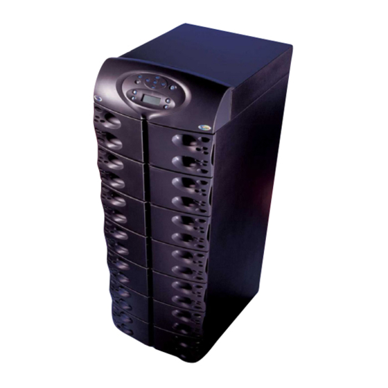
Page 8: Figure 1 Front And Back Views
Figure 1 Front and back views User Interface Power Module Bays Battery Module Bays Manual Bypass Switch (SW1) Intake Cooling Fans FRONT VIEW with bezels removed Refer to the table below for size and fully populated weight considerations. Table 1 Model 12 bay Control... -
Page 9: Modes Of Operation
Modes of Operation INPUT FILTER INTERFACE Normal Mode The Power Module rectifiers derive power from a utility AC source and supply regulated DC power to the inverter. The module’s inverter regenerates precise AC power to supply the connected equipment. The battery charger is in the Power Module and maintains a float-charge on the batteries. Backup Mode When AC utility fails, the connected equipment is supplied power by the inverter, which obtains energy from the Battery Modules. -
Page 10: Major Components
Major Components The following is a general description of each compo- nent and its functions. Please review this section carefully, as it will give you a better understanding as to how the Nfinity operates. 1.3.1 Unit Frame The front of the Nfinity consists of a series of plastic bezels. -
Page 11: Power Module
1.3.4 Power Module Each power module is an independent 4 kVA, 2.8kW unit, consisting of a power factor corrected recti- fier, battery charger and inverter, with associated monitoring and control circuitry. The modules are paralleled to provide greater capacity and/or redundancy. Modules may be added or replaced on-line with no interruption or danger to the connected equipment. -
Page 12: Installation
NSTALLATION Inspection Upon receiving the UPS, examine the packaging for any signs of mishandling or damage. If any dam- age is noted, call your local dealer or Liebert representative and/or notify your carrier. 2.1.1 Environment NOTE Operating in temperatures above 77°F (25°C) will reduce battery life. The UPS environment must be free of conductive contaminants and excessive moisture (water and condensation), flammable vapors, chemical fumes, corrosive gases and liquids. -
Page 13: Unloading
Unloading 2.2.1 Unloading the UPS CAUTION This UPS is very heavy (see weight in Table 1). At least two people should assist in unloading it from the pallet. 1. Use a ratchet or wrench, 1/2" (13mm), to remove the four mounting bolts from the front and rear pallet brackets. -
Page 14: Stationary Mounting
5. Once the UPS is in the desired location, adjust the leveling feet to secure its position. 2.2.2 Stationary Mounting Additional stability can be added by bolting the mounting brackets (used in shipping) to the floor, as shown below left. Shipping Brackets Used for Stationary Mounting For greater stability, use a higher-grade bolt. -
Page 15: Cable Installation
Cable Installation 2.3.1 Wiring Preparation WARNING Please read this section thoroughly before attempting to install wiring to this unit. This UPS should be installed by a qualified / certified electrician. Removing the Cover Plates On the back Remove Cover Plates of the UPS, cover plates are over the... - Page 16 Input Wiring (TB1) To connect the input wiring, follow these steps: 1. Locate the input wiring access, remove the knockout and pull the three input wires through it, allowing some slack for installation. 2. Secure the conduit to the rear panel of the UPS. 3.
-
Page 17: Connecting To External Panel Boards
2.3.2 Connecting to External Panel Boards The following instructions are also shipped attached to the rear of the unit. INPUT CABLING AND PROTECTION Table Below Applies to 12-20kVA Scalable Systems: Stand-alone UPS or UPS equipped with a Maintenance Bypass Cabinet (Without Transformer) Input Voltage –... -
Page 18: Output Cabling
UPS Output Terminal Block (TB3) If connected equipment operates at 208VAC only, use a single-phase panel board connected to the UPS as follows. Setup 1 - 208 VAC Max output current = 96A Grounding Electrode Conductor (Field connection must be made) Connected Equipment Connected Equipment Ground... -
Page 19: Repo Connection
2.3.3 REPO Connection The Nfinity is equipped with a Remote Emergency Power Off (REPO) connection. NOTE A jumper is factory installed between pins 1 & 2 to disable the Control Switch (SW2). This will prevent the unit from being started during installation. This jumper must be removed in order to start the unit. -
Page 20: Communications
Communications 2.4.1 COM Ports Nfinity is able to communicate through multiple communication ports simultaneously. Use only Liebert-provided communication cards. Connect only Signal Edge Low Voltage (SELV)/Class 2 cir- cuits when connecting to any communication port. There are two DB-9 COM ports available on the rear of the Nfinity. COM1 - Relay Contacts Relay contacts are available through a DB-9F communications connector. -
Page 21: Operating
PERATING NSTRUCTIONS Controls and Indicators 3.1.1 Display Controls The User Interface Module informs you of the status of the UPS and lets you configure the UPS to your own needs or preferences. The module consists of a series of Status LEDs, an LCD display window (four lines of 20 characters each), and buttons for navigation, as displayed below. -
Page 22: Status Led Modes
Status LED Modes UPS is Off or Initializing UPS is On, Utility is Good and Output is Off UPS is On, Utility is Good and Output is On (Normal Operation) UPS is On, Utility is Bad and Output is On (On Battery Operation) UPS is On, Utility is Bad and Output is Off... -
Page 23: Operating Procedures
Operating Procedures 3.4.1 Start-Up and Initialization Follow these steps to start up the UPS. 1. Ensure the manual bypass switch is in UPS position. Close Input Circuit Breaker (CB1) and close the Control Enable Switch (SW2). You should see the following on the LCD display window: UPS Initializing Please wait... -
Page 24: Main Menu
Main Menu After initialization, the status of the UPS, review the event log and active alarms, configure your UPS and even receive instructions on replacing modules. The Main Menu is divided into eight sub-menus as shown below: UPS Status UPS Status Present Load Redundant Status Battery Status... -
Page 25: Ups Status Screen
3.5.1 UPS Status Screen From the Main Menu the user may select UPS Status and press the user may access any information on the present condition of the UPS. Note the chart below when reviewing the UPS. Present Load On Mains/Utility Output: kVA xx.x Output: kW xx.x Output: pf xx.x... -
Page 26: Ups Configuration Screen
3.5.2 UPS Configuration Screen Review Settings Follow this procedure to review your UPS configuration settings. Follow the menus below by pressing to review the settings. Voltage Voltage Settings Input 208/120 Output 208 Frequency Frequency Settings Frequency Hz: 60 Sync Range Hz: +/- 5.0 Slew Range Hz/S: 3.0 Battery Battery Settings... - Page 27 Change Configuration Settings - Change Settings Menu Starting from the Main Menu, locate and press UPS Configuration. From the UPS Configuration screen, select the Change Settings option. You may configure Nfinity from a large variety of selec- tions. Items indicated by an asterisk (*) are the selected settings. Input Voltage: Select the required input voltage set- ting.
- Page 28 Auto Battery Test: Configure when and how often the Nfinity’s automatic battery test will run. This test is designed to ensure battery system integrity and provide early warning of problems. Auto Battery Test Interval Start Day Start Time Interval Batt Test Interval 1 week * 2 weeks 3 weeks...
- Page 29 Set Date/Time: Allows user to enable/disable DST (Daylight Saving Time), change the Day, Date and Time setting on Nfinity. When enabled, the time will automatically adjust to Daylight Saving Time. Set Time/Date DST Mode Set Time/Date DST Mode DST Mode Enabled * Disabled Set Date/Time...
- Page 30 Bypass Alarm Mode: Allows the user to enable/dis- able alarm, indicating that the bypass is not quali- fied. Bypass Alarm Mode > Enable Disable Intelli-Battery Ca.: Allows the user to enter the quantity of intelligent battery cabinets installed. Enter Intelli- Battery cabinet count Air Filter Reminder: Allows the user to set a warn-...
-
Page 31: Display Date/Time
UPS Configuration Screen - Service Mode Menu Service Mode contains site identification information about the UPS system. The data is entered by Liebert Global Services (LGS). To view the data, go to the Main Menu, select UPS Configuration and press . -
Page 32: Event Log
3.5.4 Event Log Accessing the Event Log enables the user to scroll through the Nfinity’s past 255 occur- rences. To open the Event Log, start at the Main Menu, select Event Log and press Main Menu UPS Status UPS Configuration Display Date/Time >... -
Page 33: Module Replacement
3.5.7 Module Replacement The user interface also supplies instructions for removing and replacing modules. From the Main Menu, access the module replacement screen and select the type of module. Refer to the screens below: Control Module w/ Redundant Cntl Mod Replacement 1. -
Page 34: Service Tools For Liebert Global Services Engineers
3.5.8 Service Tools for Liebert Global Services Engineers The Service Tools option is intended for use by Liebert Global Services engineers or Liebert-trained engineers to carry out certain tests and clear failures. These are advanced menus, entering changes may adversely affect UPS operation. From the Main Menu, shown below left, select Service Tools and press Main Menu UPS Status... -
Page 35: Troubleshooting
ROUBLESHOOTING Active Alarms In the event of an alarm, the User Interface LCD will display the last message regardless of the default screen. A list of possible alarm messages is displayed below. If you encounter one of these or other alarm messages and are unsure of the corrective action to take, please contact a qualified Lie- bert representative at the number listed on the back of this manual. - Page 36 User Interface Text Assert manual A user-initiated transfer to bypass will bypass assert this alarm, instructing the user to enable the manual bypass switch. Once the manual bypass is asserted, the alarm will clear. This is a non-mutable alarm. Remote shutdown The most likely cause is that the incorrect on COM port 1 cable has been connected to the COM...
-
Page 37: Module Led Indication
Module LED Indication Every Battery, Power and Control Module features two LEDs to help inform the user of the module status, as shown below left. Refer to Table 2 for details. Control Module Power Module Battery Module Table 2 Green Status LED Status Yellow Fault LED (Green) -
Page 38: Module Replacement
Module Replacement Follow the instructions below when replacing or adding a Control, Battery or Power Module to the system. To order additional modules, contact your Liebert representative or call 1-800-LIEBERT. 4.3.1 Removing Modules 1. Remove bezel cover of appropriate module. When replacing a Power or Battery Module, verify the faulty module by confirming the yellow LED is lit. -
Page 39: Adding Or Replacing Modules
4.3.2 Adding or Replacing Modules NOTE Power Modules must be installed in the top half of the Nfinity frame. Battery Modules can be installed in any bay of the UPS frame. 1. Lift module to appropriate bay, resting end of module on bay shelf. -
Page 40: Maintenance
AINTENANCE Maintenance 5.1.1 Proper Care Keeping your Liebert Nfinity UPS operating properly is imperative to optimal performance and life of the unit. It is recommended that a certified technician perform preventive and corrective mainte- nance. Liebert Global Services (LGS) is dedicated to ensuring the highest level of performance and unmatched support for your Nfinity UPS. -
Page 41: Specifications
PECIFICATIONS General & Environmental Unit Rating Conducted and Radiated EMC Levels Compliant Safety Standards Compliant Immunity Standards Mechanical Width Dimensions Depth Height Environmental Operating Temperature (max) Relative Humidity Maximum operating altitude Nominal heat dissipation Acoustic noise level Input Data Nominal input voltage Voltage Range (Typical) Power factor Input frequency (nominal) - Page 42 Specifications...
- Page 44 ™ Power System Nfinity The Company Behind the Products With over a million installations around the globe, Liebert is the world leader in computer protection systems. Since its founding in 1965, Liebert has developed a complete range of support and protection systems for sensitive electronics: •...