Table of Contents
Quick Links
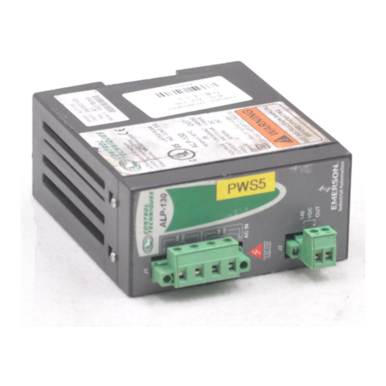
ALP-130 and ALP-430
Auxiliary Logic Power Supply
Installation Manual
Information furnished by EMERSON Motion Control is believed to be accurate and
reliable. However, no responsibility is assumed by EMERSON Motion Control for its use.
EMERSON Motion Control reserves the right to change the design or operation of the
equipment described herein and any associated motion products without notice.
EMERSON Motion Control also assumes no responsibility for any errors that may appear
in this document. Information in this document is subject to change without notice.
P/N 400514-01
Rev.: A2
Date: October 22, 1999
© 1999 EMERSON Motion Control. All rights reserved.
Table of Contents

Related Manuals for Emerson ALP-130


Summary of Contents for Emerson ALP-130
- Page 1 Information furnished by EMERSON Motion Control is believed to be accurate and reliable. However, no responsibility is assumed by EMERSON Motion Control for its use. EMERSON Motion Control reserves the right to change the design or operation of the equipment described herein and any associated motion products without notice.
- Page 2 EMERSON Motion Control. The following are trademarks of EMERSON Motion Control and may not be reproduced in any fashion without written approval of EMERSON Motion Control.
-
Page 3: Customer Service
Eden Prairie, Minnesota 55344-3620 U.S.A. Telephone: (612) 995-8000 or (800) 397-3786 It is EMERSON Motion Control’ s goal to ensure your greatest possible satisfaction with the operation of our products. We are dedicated to providing fast, friendly, and accurate assistance. - Page 4 Technical Service (612) 995-8033 Email: [email protected] EMERSON Motion Control’ s products are backed by a team of professionals who will service your installation wherever it may be. Our technical service center in Minneapolis, Minnesota is ready to help you solve those occasional problems over the telephone.
-
Page 5: Document Conventions
(612) 995-8000 Customer Service (Sales) Email: [email protected] Authorized EMERSON Motion Control distributors may place orders directly with our Order Processing Department by calling the number listed above. For information on your local distributor, call EMERSON Motion Control. -
Page 6: Safety Instructions
ALP-130 and ALP-430 Auxiliary Logic Power Supply Installation Manual Button names are in italic: OK button. Source code is printed in Courier font: Case ERMS. In addition, you will find the following typographic conventions throughout this manual. This Represents Characters that you must type exactly as they appear. For... - Page 7 involved. In addition, this individual has the following qualifications: • Is trained and authorized to energize, de-energize, clear, ground and tag circuits and equipment in accordance with established safety practices. • Is trained in the proper care and use of protective equipment in accordance with established safety practices.
- Page 8 ALP-130 and ALP-430 Auxiliary Logic Power Supply Installation Manual E Series Only For the purpose of this manual and product, the “E ” symbol indicates information about the E Series drive specifically. Throughout this manual, the word "drive" refers to an Epsilon or E Series drive.
-
Page 9: Ce Declaration Of Conformity
The “conditions of acceptability” required by UL are: • The ALP-130 ambient temperature must be 40° C (104° F) or less. • The ALP-430 ambient temperature must be 50° C (122° F) or less. -
Page 10: Declaration Of Conformity
ALP-130 and ALP-430 Installation Manual Declaration of Conformity EMERSON Motion Control Manufacturer’s Name: 1365 Park Road Chanhassen, MN 55317 Manufacturer’s Address: Declares that the following products: Drive Accessories Products Description: RSR-2 and ALP-430 Model Number: Conforms to the following product specification: The products herewith comply with the requirements of the Low Voltage Directive (LVD) 73/23/EEC. -
Page 11: Supplementary Information
E Series Digital Servo Drive Products Description: EN-204, EN-208 and EN-214 Model Number: This declaration covers the above products with the ALP-130 Backup Logic Power Supply and ECI-44 System Options: Screw Terminal Interface. Conforms to the following product specification: Electomagnetic Compatibility (EMC):... -
Page 13: Table Of Contents
Power Supply Specifications......9 ALP-130 Dimensions........9 ALP-430 Dimensions. -
Page 15: Auxiliary Power Supply
Note The ALP-130 is considered a Class 2 device. As such, there is not a connection for PE on the ALP-130. Protect Class 2 referes to any equipment in which protection against electrical shock does not rely on basic insulation only, but in... -
Page 16: Alp-130
ALP-130 and ALP-430 Installation Manual to most mounting tracks or enclosures and includes the screw terminal plug connectors to mate with the auxiliary supply receptacle on the drives and the drive end connector kit and includes four (4) ALPC-xxx cables to mate with the recepticle... -
Page 17: Installation
Installation ALP-130 Wiring Example 230 VAC Backup Power ALPC-xxx Cable... -
Page 18: Alp-430 Wiring Example
ALP-130 and ALP-430 Installation Manual ALP-430 Wiring Example 230 VAC Backup Power ALPC-xxx Cable... -
Page 19: Installation Procedure
Installation Installation Procedure Follow the wiring diagrams below for the ALP-130/-430 installation and fusing. Use #16 to 18 AWG, 600V, insulated, stranded wire for AC in and DC out wiring. The ALP-130 and ALP-430 package includes the cable assembly that mates with the 2-position header(s) on your drive(s). - Page 20 ALP-130 and ALP-430 Installation Manual Figure 2: ALP-430 Connections and Internal Wiring Diagram...
-
Page 21: Alpc-Xxx Cable Installation Instructions
ALPC-xxx Cable Installation Instructions The ALPC-xxx cable is designed to connect an auxiliary logic power supply such as the ALP-130/430 to the E Series drive. It includes a 2-position plug that mates with the 2-position header (J3) on your E Series drive and flying leads that connect to the auxiliary logic power supply. - Page 22 ALP-130 and ALP-430 Installation Manual Two position receptacle The mating connector/cable assembly ALPC-xxx plugs into the receptacle. Additional cables available from EMERSON Motion Control. Figure 1: Signal Description with the New Style Two Position Receptacle in the J3 Location All drives serial numbers 9747 and lower and some drive serial number 9748 or higher, use a spring terminal for J3 rather than a header.
-
Page 23: Specifications
1.6 lbs ALP-130 50° C (122° F) 40 Watts 30 Watts (.07 kg) 115/230 VAC 140 VDC 7.7 lbs ALP-430 50° C (122° F) 130 Watts (4) x 20 Watts (3.5 kg) ALP-130 Dimensions 2.0 min. 0.25 0.25 2.0 min. -
Page 24: Alp-430 Dimensions
ALP-130 and ALP-430 Installation Manual ALP-430 Dimensions 2.95 2.0 min. 0.35 6.53 0.18 0.22 0.23 7.50 7.05 2.25 2.0 min. 0.25 0.25...