Hitachi SJ300 Series Quick Reference Manual
Hide thumbs
Also See for SJ300 Series:
- Instruction manual (295 pages) ,
- Manual (48 pages) ,
- Replacement manual (23 pages)

Related Manuals for Hitachi SJ300 Series


Summary of Contents for Hitachi SJ300 Series
- Page 1 SJ300 Series Inverter Quick Reference Guide • Three-phase Input 200V Class • Three-phase Input 400V Class UL Version Models CE Version Models Hitachi Industrial Equipment Systems Co., Ltd. Manual No. NB6131XF • September 2006...
-
Page 3: Ul ® Cautions, Warnings, And Instructions
Caution: Be sure to read the SJ300 Inverter Manual and follow its Cautions and Warnings for the initial product installation. This Quick Reference Guide is intended for reference use by experienced users in servicing existing installations. ® Cautions, Warnings, and Instructions Wiring Warnings for Electrical Practices and Wire Sizes The Cautions, Warnings, and instructions in this section summarize the procedures necessary to ensure an inverter installation complies with... - Page 4 200V Models Motor output Torque Inverter Wire Size (AWG) Model ft-lbs (N-m) 18.5 –185LFU –220LFU 1/0 AWG –300LFU 1/0 || 1/0 AWG –370LFU 1/0 || 1/0 AWG –450LFU 1/0 || 1/0 AWG 10.1 13.7 –550LFU 2/0 || 2/0 AWG 10.1 13.7 400V Models Motor output...
-
Page 5: Wire Connectors
400V Models Motor output Torque Inverter Wire Size (AWG) Model ft-lbs (N-m) –1320HFU/E 3/0 || 3/0 10.1 13.7 –1500HFU/E 3/0 || 3/0 10.1 13.7 Wire Connectors Warning: Field wiring connections Terminal (ring lug) must be made by a UL Listed and CSA Cable support Certified ring lug terminal connector sized for the wire gauge being used. - Page 6 200V Models Motor output Inverter Ampere Rating for Model Fuse or Breaker –300LFU –370LFU –450LFU –550LFU 400V Models Motor output Inverter Ampere Rating for Model Fuse or Breaker 0.75 –007HFU/E –015HFU/E –022HFU/E –037HFU/E 7 1/2 –055HFU/E –075HFU/E –110HFU/E –150HFU/E 18.5 –185HFU/E –220HFU/E –300HFU/E...
-
Page 7: Motor Overload Protection
Motor Overload Protection Hitachi SJ300 inverters provide solid state motor overload protection, which depends on the proper setting of the following parameters: • B012 “electronic overload protection” • B212 “electronic overload protection, 2nd motor” • B312 “electronic overload protection, 3rd motor”... - Page 8 Power Circuit Terminals Inverter models: –004LFU, –007 to –055LFU, –007 to –055HFE, HFU (L1) (L2) (L3) (T1) (T2) (T3) (R0) (T0) (+1) (–) (RB) Jumper Inverter models: –075LFU –075HFE, HFU, –110LFU (L1) (L2) (L3) (T1) (T2) (T3) –110HFE, HFU (+1) (–) (RB) (G) (G)
-
Page 9: Control Circuit Terminals
Control Circuit Terminals 5 3 1 L O OI PLC CM1 6 4 2 Analog Analog Power Logic Logic Alarm inputs outputs inputs outputs relay Terminal Description Ratings and Notes Name +24V power for inputs 24VDC supply, 100 mA max. +24V common Common for 24V supply, FW, TH, inputs 1 to 8, and... - Page 10 Terminal Description Ratings and Notes Name PWM output 0 to 10VDC, 1.2 mA max., 50% duty cycle Voltage analog output 0 to 10VDC, 2 mA max. Current analog output 4-20 mA, nominal load impedance 250Ω Common for analog Sum of OI, O, and H currents inputs (return) Analog input, current...
-
Page 11: Basic Wiring Diagram
Basic Wiring Diagram The following wiring diagram shows the power and motor connections for basic operation. The optional signal input wiring supports external Fwd and Rev Run command, and a speed potentiometer. SJ300 From 3-phase power input (L1) (T1) source (See specifications Motor (L2) -
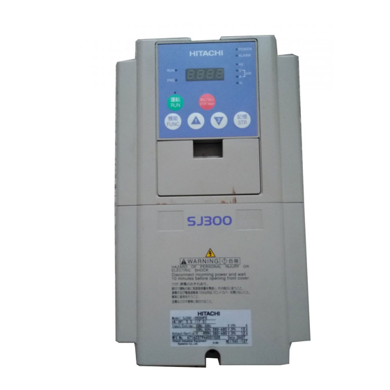
Page 12: Inverter Keypad Operation
Inverter Keypad Operation Run/Stop LED Parameter Display Power LED Program/Monitor LED Alarm LED POWER HITACHI ALARM Display Units LEDs Hertz Volts or Amperes 5 0.0 (kW = both ON) Percent Potentiometer STOP RESET Enable LED Potentiometer FUNC. Function Key Up/Down Keys... - Page 13 • Stop/Reset Key – Press this key to stop the motor when it is running (uses the programmed deceleration rate). This key will also reset an alarm which has tripped. • Potentiometer (OPE–SRE only) – Allows an operator to directly set the motor speed when the potentiometer is enabled for output frequency control.
-
Page 14: Monitor Mode
Keypad Navigation Map Monitor Mode Program Mode D002–D090 Edit D001/F001 FUNC. 0.0 0 0.0 0 U 0 1 2 FUNC. FUNC. U 0 0 1 0 9 0 P 0 4 9 FUNC. 0 0 1 P 0 4 9 FUNC. -
Page 15: Powerup Test
Powerup Test The Powerup Test procedure uses minimal parameter settings to run the motor. The procedure describes two alternative methods for commanding the inverter: via the inverter keypad, or via the logic terminals. • Check power input and motor output wiring (see page 9 diagram). •... -
Page 16: Error Codes
Error Codes The SJ300 series inverters will trip on over-current, over-voltage, and under-voltage to protect the inverter. The motor output turns OFF, allow- ing the motor to free-run to a stop. Press the Stop/Reset key to reset the inverter and clear the error. Basic Error Codes Error Name... - Page 17 Error Name Probable Cause(s) Code Inverter thermal trip • Inverter internal temperature is above the threshold Gate array error • An internal inverter error has occurred (CPU / gate array IC) Phase failure detection • One of three lines of the 3-phase power is missing IGBT error •...
-
Page 18: Restoring Factory Default Settings
Restoring Factory Default Settings Action Display Function/Parameter “B” Group selected - - - Press the FUNC. keys as needed. First “B” Group parameter 0 0 1 Press the key. FUNC. 0 8 5 Country code for Press/hold until... initialization selected 00 = Japan Press the key. -
Page 19: Parameter Tables
Parameter Tables “D” Group: Monitoring Functions Parameter Monitoring Func. Name / Description Units Code D001 Output frequency monitor D002 Output current monitor D003 Rotation direction monitor — Forward Stop Reverse Direction D004 Process variable (PV), PID feedback monitor D005 Intelligent input terminal status —... - Page 20 Trip History and Programming Error Monitoring Func. Name / Description Units Code D080 Trip count – cumulative number of trip events Events D081 Trip history – event 1 (newest) — see map below — D082 Trip history – event 2 (2nd newest) — see map below —...
-
Page 21: "F" Group: Main Profile Parameters
Parameter tables for user-settable functions follow these conventions: • Some parameters have 2nd and 3rd motor equivalents, indicated by the x2xx and x3xx parameter codes in the left-most column. • Some parameters specify an option code. Where applicable, the options codes will be in a bulleted list in the Name/Description column. -
Page 22: "A" Group: Standard Functions
“A” Group: Standard Functions Default Func. Name / Description Value Code Value –FE/ FU/FR A001 Frequency source setting 01 / 01 / 02 • 00 Keypad potentiometer • 01 Control terminal • 02 Function F001 setting • 03 RS485 serial command •... - Page 23 Default Func. Name / Description Value Code Value –FE/ FU/FR A020/ Multi-speed frequency setting 0.00 A220/ A320 A021 Multi-speed frequency settings 0.00 (for both motors) A035 A038 Jog frequency setting 1.00 A039 Jog stop mode • 00 Free-run stop, jogging disabled during motor run •...
- Page 24 Default Func. Name / Description Value Code Value –FE/ FU/FR A057 DC braking force for starting A058 DC braking time for starting A059 DC braking carrier frequency setting A061/ Frequency upper limit setting 0.00 A261 A062/ Frequency lower limit setting 0.00 A262 A063...
- Page 25 Default Func. Name / Description Value Code Value –FE/ FU/FR A093/ Deceleration (2) time setting 15.0 A293/ A393 A094/ Select method to switch to Acc2/Dec2 profile A294 • 00 2CH input from terminal • 01 transition frequency A095/ Acc1 to Acc2 frequency transition point A295 A096/ Dec1 to Dec2 frequency transition point...
-
Page 26: "B" Group: Fine-Tuning Functions
“B” Group: Fine-tuning Functions Default Func. Name / Description Value Code Value –FE/FU/FR B001 Selection of automatic restart mode • 00 Alarm output after trip, automatic restart disabled • 01 Restart at 0Hz • 02 Resume operation after frequency matching •... - Page 27 Default Func. Name / Description Value Code Value –FE/FU/FR B022 Overload restriction setting Rated current x 1.50 B023 Deceleration rate at overload restriction 1.00 B024 Overload restriction operation mode (2) • 00 Disabled • 01 Enabled for accel and constant speed •...
- Page 28 Default Func. Name / Description Value Code Value –FE/FU/FR B043 Torque limit (3) (reverse-driving in 150. 4-quadrant mode) B044 Torque limit (4) (forward-regenerating in 150. 4-quadrant mode) B045 Torque limit LADSTOP enable • 00 Disable • 01 Enable B046 Reverse Run protection enable •...
- Page 29 Default Func. Name / Description Value Code Value –FE/FU/FR B095 Dynamic braking control • 00 Disable • 01 Enable during RUN only • 02 Enable always B096 Dynamic braking activation level 360/ B098 • Thermistor for thermal protection control • 00 Disable •...
-
Page 30: "C" Group: Intelligent Terminal Functions
“C” Group: Intelligent Terminal Functions Default Func. Name / Description Value Code Value –FE/FU/FR C001 Terminal [1] function 44 option codes available C002 Terminal [2] function (see page 35) C003 Terminal [3] function C004 Terminal [4] function C005 Terminal [5] function C006 Terminal [6] function 03 / 13 / 03... - Page 31 Default Func. Name / Description Value Code Value –FE/FU/FR C031 Terminal [11] active state • 00 Normally open (NO) C032 Terminal [12] active state • 01 Normally closed (NC) C033 Terminal [13] active state C034 Terminal [14] active state C035 Terminal [15] active state C036 Alarm relay terminal...
- Page 32 Default Func. Name / Description Value Code Value –FE/FU/FR C073 Communication data length selection • 07 7-bit data • 08 8-bit data C074 Communication parity selection • 00 No parity • 01 Even parity • 02 Odd parity C075 Communication stop bit selection •...
-
Page 33: "H" Group: Motor Constants Functions
“H” Group: Motor Constants Functions Default Func. Name / Description Value Code Value –FE/FU/FR H001 Auto-tuning Setting • 00 Auto-tuning OFF • 01 Auto-tune (measure motor resistance and inductance, without rotating) • 02 Auto-tune (rotate motor) H002/ Motor data selection H202 •... -
Page 34: "P" Group: Expansion Card Functions
Default Func. Name / Description Value Code Value –FE/FU/FR H050/ PI proportional gain H250 H051/ PI integral gain H251 H052/ P proportional gain setting 1.00 H252 H060/ 0Hz SLV limit 1.00 H260 H070 Terminal selection PI proportional gain setting 100.0 H071 Terminal selection PI integral gain setting 100.0... - Page 35 Default Func. Name / Description Value Code Value –FE/FU/FR P018 Home search completion delay time setting 0.00 P019 Electronic gear set position selection • 00 Position feedback side • 01 Position command side P020 Electronic gear ratio numerator setting P021 Electronic gear ratio denominator setting P022 Feed-forward gain setting...
-
Page 36: "U" Group: User-Selectable Menu Functions
“U” Group: User-selectable Menu Functions Func. Default Name / Description Code Value Value U001 User-selected function, D001 to P049 U002 User-selected function, D001 to P049 U003 User-selected function, D001 to P049 U004 User-selected function, D001 to P049 U005 User-selected function, D001 to P049 U006 User-selected function, D001 to P049 U007... - Page 37 Intelligent Input Terminal Listing Symbol Code Input Terminal Name Reverse Run/Stop Multi-speed select, Bit 0 (LSB) Multi-speed select, Bit 1 Multi-speed select, Bit 2 Multi-speed select, Bit 3 (LSB) Jogging External DC injection braking signal Set (select) second motor data 2-stage accel and decel Free-run stop External trip...
- Page 38 Symbol Code Input Terminal Name P / PI mode selection Brake confirmation signal Orientation (home search) LAC: LAD cancel PCLR Position deviation reset STAT Pulse train position cmd enable Intelligent Output Terminal Listing Symbol Code Input Terminal Name Run signal Freq.
-
Page 39: Analog Input Configuration
Analog Input Configuration The following tables show the parameter settings required for various analog input signal types. External Trim Reverse Frequency Frequency available A006 A005 [AT] Command Command (bipolar Input Input input) ✘ ✘ [O] — [L] ✘ ✘ [OI] — [L] ✘... -
Page 40: Programming Error Codes
Analog Output Function Listing The following table shows all eight functions available for assignment to the three analog output terminals: • Terminal [FM], option set by C027 • Terminal [AM], option set by C028 • Terminal [AMI], option set by C029 Option Function Corresponding... - Page 41 Boundary defined by... Function code of Prg Error Code parameter out of bounds <, > Base parameter A061 / A261 > A004 / A204 / A304 001 201 A062 / A262 > 002 202 004 204 304 A003 / A203 / A303 >...
-
Page 42: Auto-Tuning Procedure
Boundary defined by... Function code of Prg Error Code parameter out of bounds <, > Base parameter B100, B102, B104, > B112 B106, B108, B110 B102, B104, B106, < B100 B108, B110 B100 > B102 B104, B106, B108, < B110 B100, B102 >...